


Parametric lamp
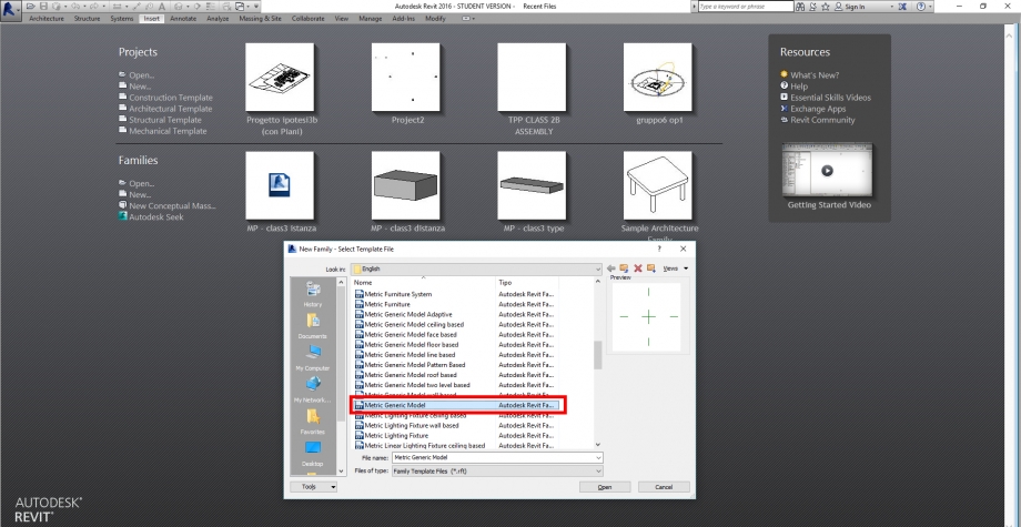
We start opening Revit, New Families and selecting Metric Generic Model to show the work space
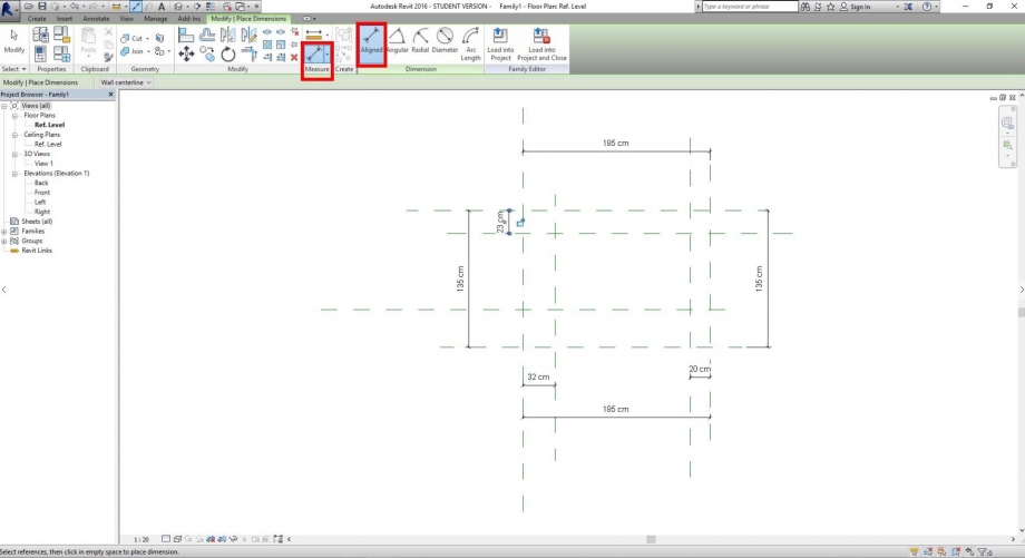
We use "Reference Plane" command to write the planes that will guide the surfaces.

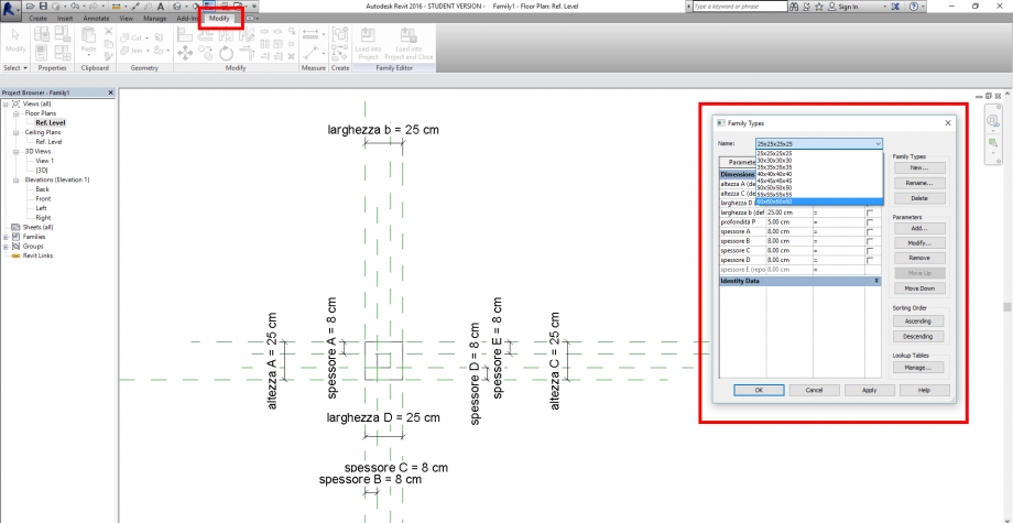
Once we wrote the planes, we use the "Measure" - "Aligned" tools to quote the distances
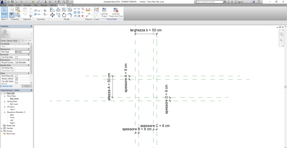
We access the propriety panel to rename the distances
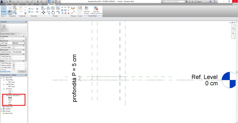
Now we go to "Forms" panel and we check "Extrusion" command. "Modify / Create Extrusion" panel is shown now, we use the "Line" command to identify the planes we want to build up.
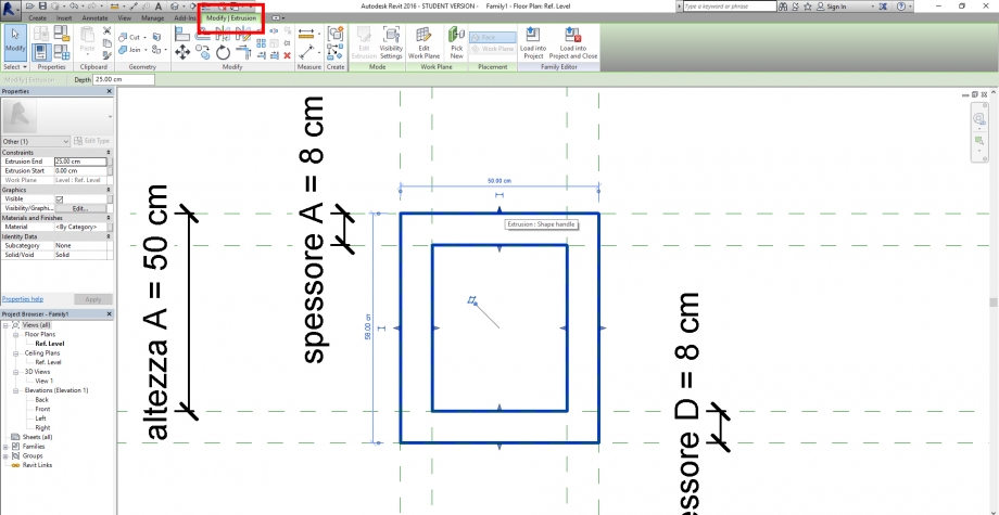
We change the view to be certain that our project is deep as we set.
Now we crerate many others family types by changing the measures and saving them. We'll need them to compose our project.
Once we saved all the new families types we are ready to have a next step, by closing this file and opening a new project.
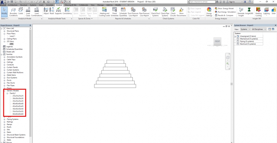
We start a new project and we load the families set before, we can find them in the Project Browser by searching "Generic Models" .
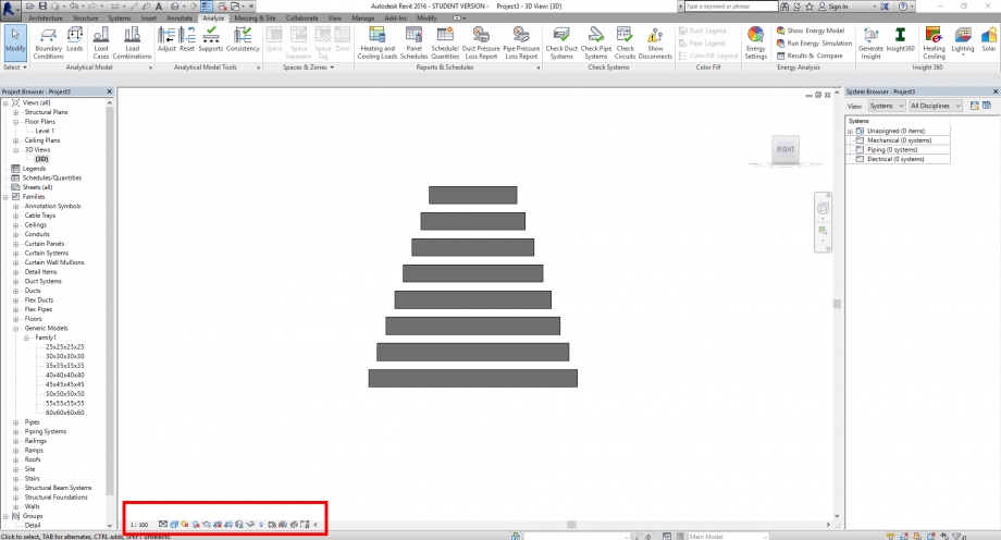
We decide which position has to be set by moving the blocks.
Once we set the distances, we give a shaded effect by selecting it in the Graphic Display options
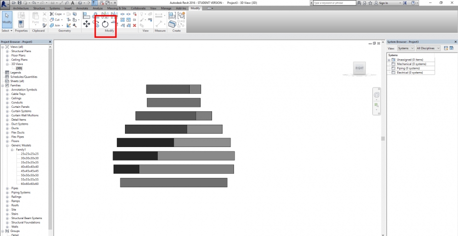
"Modify" panel helps us to turn every single type of the family

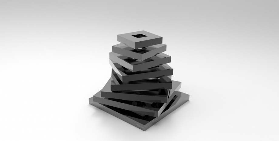
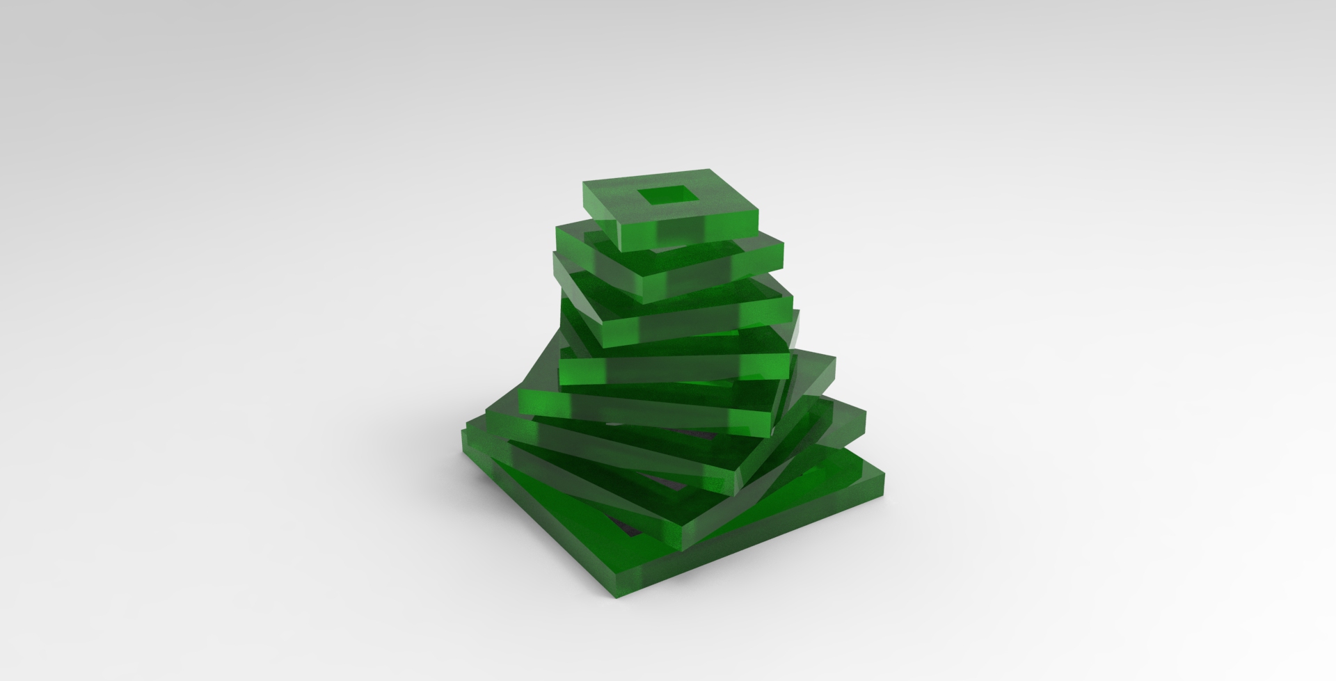
We use the 3D view to show the final result and we made a couple of rendering below to have a more final idea of the project

Commenti
Luigi Olivieri
Ven, 22/04/2016 - 16:49
Collegamento permanente
suggestion
Hi,
Nice exercise, but insetead of rotate every block manually why don't you add a parameter in the family for the angle?
Or try to use dynamo to create a series of object with constant rotation!
Luigi
MAR.PICCIONE
Sab, 23/04/2016 - 14:43
Collegamento permanente
Hi,
Hi,
thank you for your suggest, I would like to control this side of the project so I am going to try how to succeed.
Many thanks