Modeling a tree.Robinia Pseudoacacia
Modeling a tree. Robinia Pseudoacacia
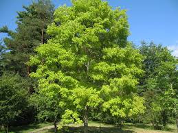
Robinia pseudoacacia, commonly known as the black locust, is a tree of the genus Robinia in the subfamily Faboideae of the pea family Fabaceae. It is native to the southeastern United States, but has been widely planted and naturalized elsewhere in temperate North America, Europe, Southern Africa and Asia and is considered an invasive species in some areas.
With a trunk up to 0.8 m diameter (exceptionally up to 52 m tall and 1.6 m diameter in very old trees), with thick, deeply furrowed blackish bark. The leaves are 10–25 cm long, pinnate with 9–19 oval leaflets, 2–5 cm long and 1.5–3 cm broad.
In Europe it is often planted alongside streets and in parks, especially in large cities, because it tolerates pollution well. The species is unsuitable for small gardens due to its large size and rapid growth, but the cultivar ‘Frisia’, a selection with bright yellow-green leaves, is occasionally planted as an ornamental tree..
Black locust has nitrogen-fixing bacteria on its root system; for this reason it can grow on poor soils and is an early colonizer of disturbed areas.
- As a first step, make an architectural survey of the chosen tree, in order to obtain its height, the diameter of the trunk, and the width of the branches at different levels.
We chose 13 different levels, since the foliage is irregularly shaped.

Now open Vasari and set Families->New conceptual mass…->mass.rft


Set the project units in centimeters trough Manage->Project units->Length->cm

2. Levels
In order to place the levels on which to create the surfaces that will shape our tree select Model->Level. Then set the levels at the chosen distance by clicking on the quotes and changing their values. You can rename the levels by clicking on them on the Project Browser window.


3. To draw the sections select each level and click Model->Circle->Draw on work plane. The radius of the circle can be changed by clicking on the relative quote.


4. Model the tree
First model the trunk, extruding the first circle to the following level.

To shape the foliage select all the remaining sections and select Modify->Create form->Solid form.

5. Set Family Types
Selecting Model->Family types you can set parameter values for your 3D model, like the diameter of each section. Parameters are related to each other, so changing one all the others will change proportionally. This way is possible to change the tree while it grows. For each parameter select Add, then set the value, (rename it), then click Instance->Ok.


6. Draw quotes
To draw the quotes select Modify->X-ray, then Aligned dimension.


7. Place mass
Now that the model is finished, open the file with the chosen area and select Model->Place Mass->Load Family->Open, and place the tree
in the area, in the right position.
In our case, the trees are located by the southern facade, which has no other element to make shadow on it.