


Seconda consegna
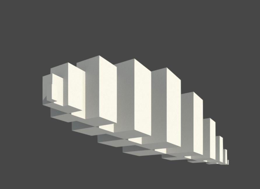
Composizione di elementi modulari posizionati seguendo le sue altezze e larghezze. Modo di procedimento: - Open a new file: Family (Metric Generic Model) - Draw 2 reference planes (RP) and add dimension between the reference planes (DI) - Create an extrusion (rectangle) and exit the sketch mode (Finish edit mode) - Align (AL) the sides of the rectangle to the reference planes, locking each one - On the elevation, draw also a reference plane, add the dimension and align and lock the rectangle's side to it - For each dimension create a parameter labelling it (height, width, thickness) - Click on Family types -> choose/modify the dimensions of each parameter and create a new type name - I created: 10x10x20m 20x20x40m 30x30x60m 40x40x80m 50x50x100m 60x60x120m 70x70x140m 80x80x160m 90x90x180m 100x100x200m - Click on Load into project (new or existing file) - The family can be found under Project Browser - Families - generic models, and each type can be added to the plan by drag-and-drop
Commenti
StefanoConverso
Lun, 09/04/2018 - 16:02
Collegamento permanente
Bel lavoro!
ma la descrizione del processo è totalmente assente e la pianta in PDF allegata non va,
devi costruire un post con il processo, bastano pochi passaggi.