


Table
For this second consegna I decide to create a table, using different familys and then joinig pieces together in oun - main family. Here is, how i did it:
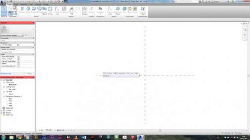
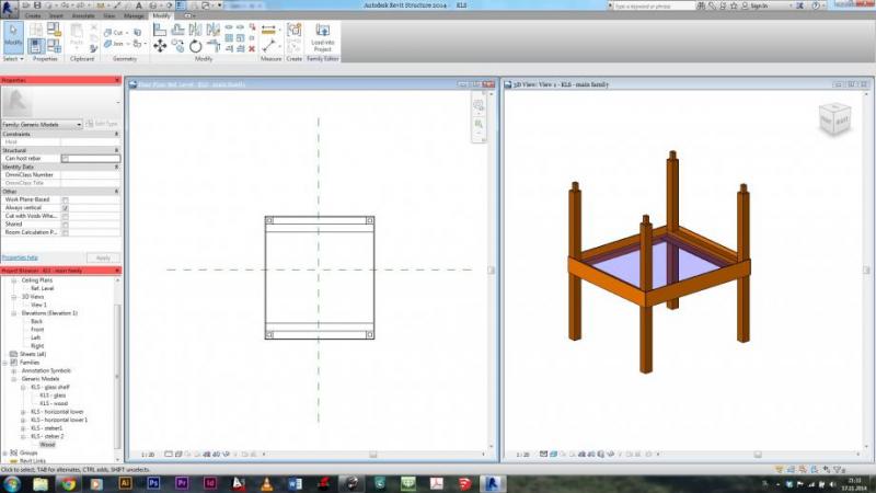
1. I created a main family - using template Metric Generic Model:
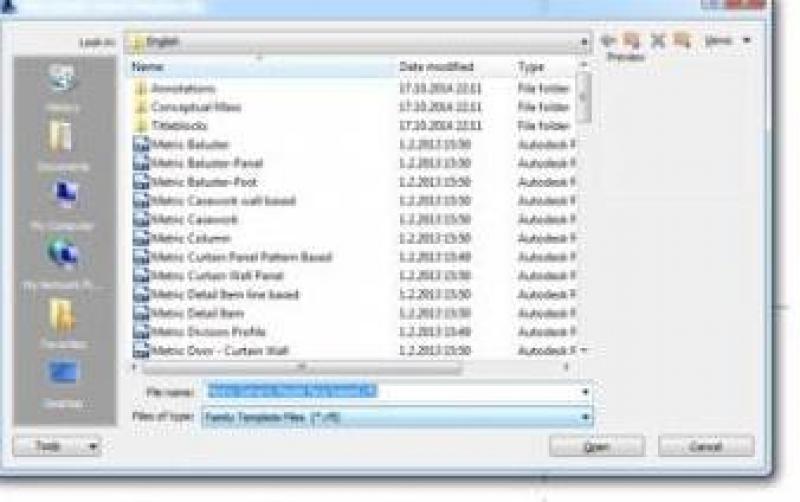
2. I created new family for the first part of the table. Keep in mind that every family, that we create and we will be later importing in the main family, must be Metric Generic Model face based:
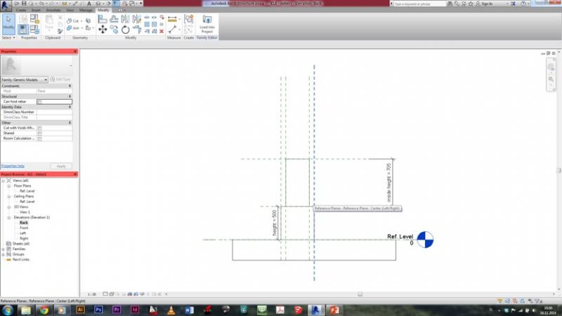
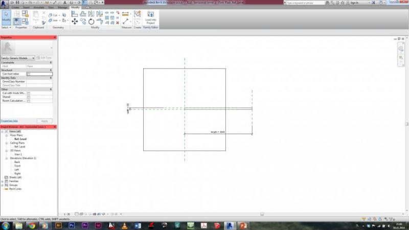
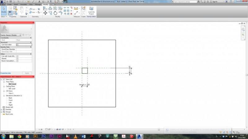
3. In this face based family in created an extrusion, which will be my loumn, for the table. I set the width, length and height to be my parameters. I did that by creating reference planes, aligning the sides of my extusion to those planes, and setting the distance between planes to be paramaeters:
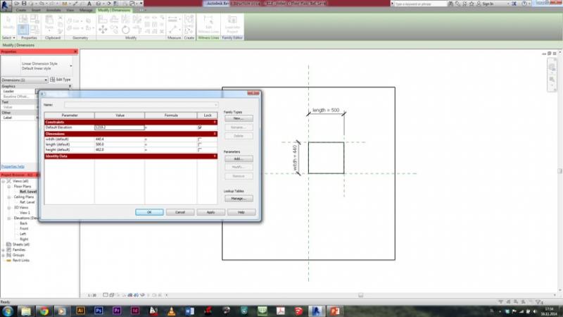
4. I made another extrusion above the one already made, which will be a part of my column as well. It's shape is as well controled with parameters as seen on the picture - the distance from the edge of the one extrusion bellow is the same for all four sides of my new extrusion. That was made just like before - creating reference planes, aligning extrusion to them, and setting the distances between those reference planes and the ones previously created to be parameters:
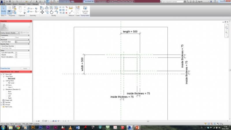
5. A parameter for the height of this second extrusion was also needed. The lower point of extrusion was locked to the heighest point of the first extrusion, while for the heighest point of this second extrusion, another reference plane was made. The heighest point was then aligned to this reference plane, and the distance between this reference plane and the one controlling the height of the first extrusion, was set as the parameter for the height of the second extrusion:
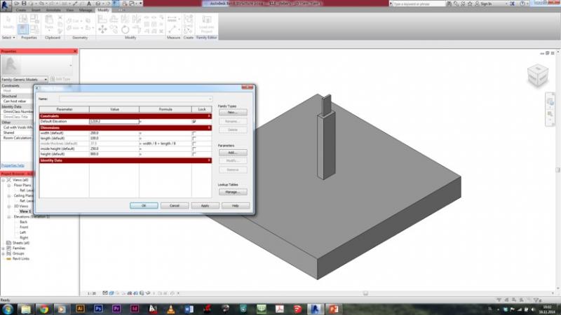
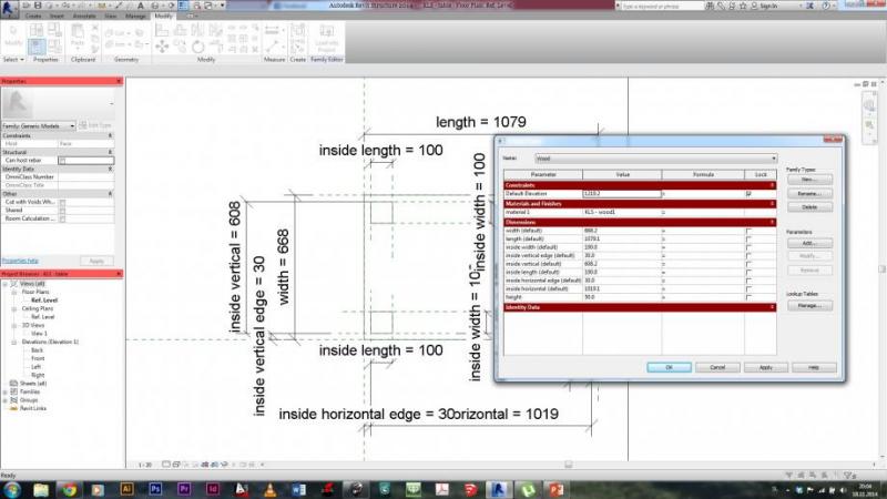
6. Here are all the parameters, used for this object. The thickness of the heigher extrusion is controled by the length and width of the lower parameter.
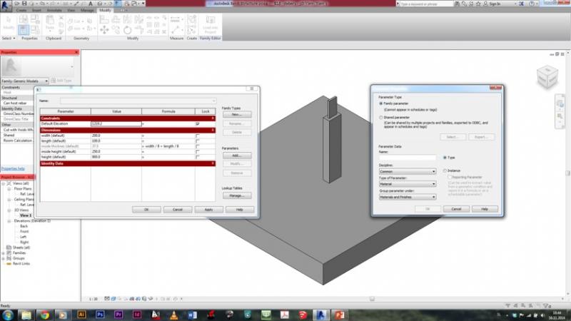
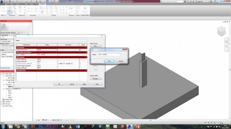
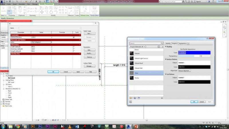
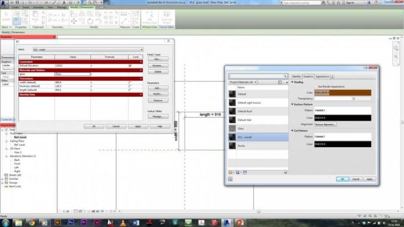
7. I created a parameter for the material as well. By clicking on Add.. in parameters menu I opened a new menu, where i set name for my new material paramater and i switched the Type of parameter to Material:
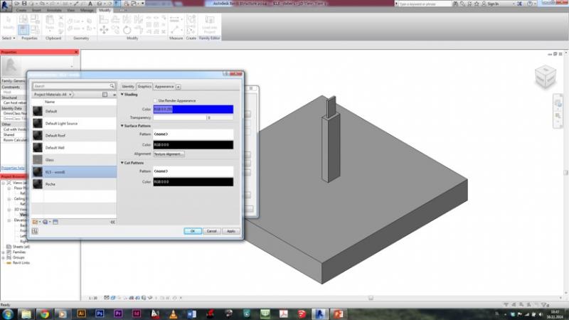
8. When this was done, in material section of parameters, I clicked on the value box, to change the properties of the material parameter. I duplicated poche material, changed the name and give my material apropriate colour:
9. After that, I also created a new family type, by clicking on New... under family types section. I created a family type wood1. I could also created another family type, which then helps me, to change family type in the main family.
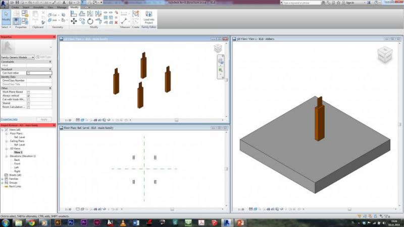
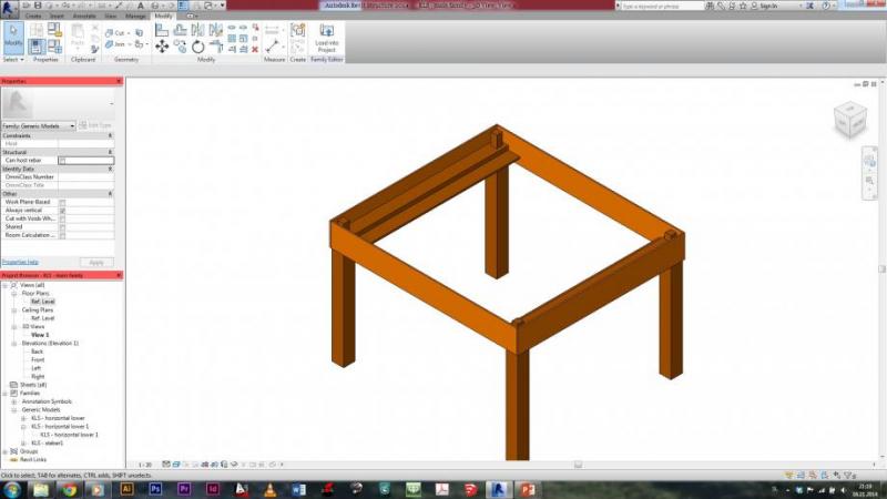
10. And so I created my first part of the table, which I than imported into my main family by choosing Import into project. In my main family I then had 3 different options how I wish to put my model - since there was nothing yet in this family, I choose option Place on Work plane. I placed four columns in my main family:
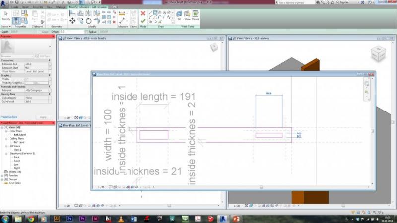
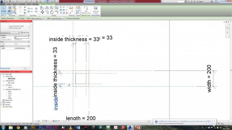
11. After that, I started doing second part of my table - horizontal axis. As before, I created new family -face based. I created extrusion and reference planes as before and set parameters as before. But I wanted to have holes in this extrusion - by clicking on edit extrusion I draw holes, which I needed:
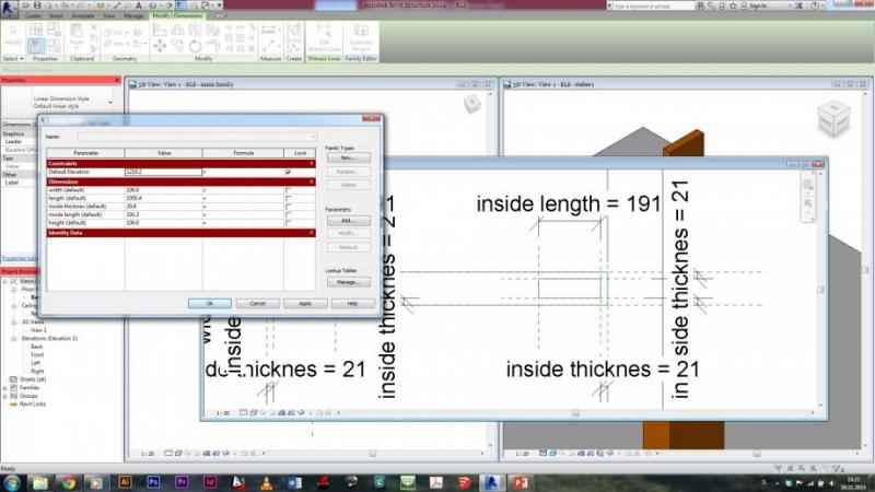
12. When the holes were created, I also created parameters for their size. All was done with creating more reference planes, aligning holes to them and setting distances between planes to be parameters. And I also created parameters for material as before, but this time I created another Family style with another material - steel. So I can now chose in my main family if I want this part of table to be made in wood or in steel.
13. When created, this part of the table was also imported in main family. But this time, when importing, I choose option Place on Face, so I put my new part directly on the one, created before. All that was left, was to adjust the parameters, so that the parts would fit together:
14. So this previosuly created part is meant to hold a glass shelf beneath the table. So I thought I could also creat something, which would go all around this glass shelf. And i created another family - face based. In this one I created another extrusion and set the parameters for both the dimensions and the material as before:
15. This one was also imported in main family, also with option Place on Face. Those wooden ''planks'' should be glued on the model. After adjusting the parameters, the model now looked like this:
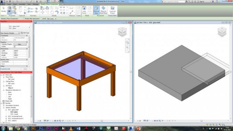
16. Now i needed to create a shelf to be put on this ''shelf-holders''. It was done as everything before - extrusion, parameters. The only difference is, that i created two family types, because I wanted a shelf to be either in wood or in glass. This was created as with the shelf-holders, which are made either in steel or in wood:
17. The shelf was then imported into project, the parameters for the dimensions were adjusted:
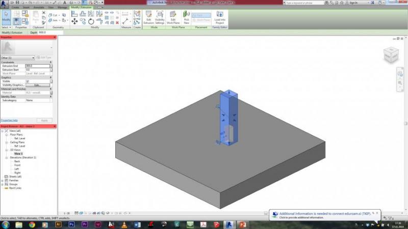
18. Next part was the second part of the column - one, which allow me, to build a different sizes of things - not just tables, but also cupboards or something similar. First, I created the extrusion for the column, and set width, length and height as paramaeters:
19. After that, I created a hole in the lower part of the column, using function Void Forms - this one creates an empty space inside our extrude. The void form was created in the same way as extruison for the column. Width and length were depicted as paramaeters of thickness - distance from the edge of column:
20. Void form also has a height - the lowest point was aligned with the lowest point of the extrusion of the column, for the heighest point i created another parameter, so I could as well control the height of the Void:
21. After this void form, I created another extrusion at the top of the column, as I did with the first column, that i created at the point 9. Also created parameter for material of the column. After that, this part was imported into main family. The whole model now looked like that:
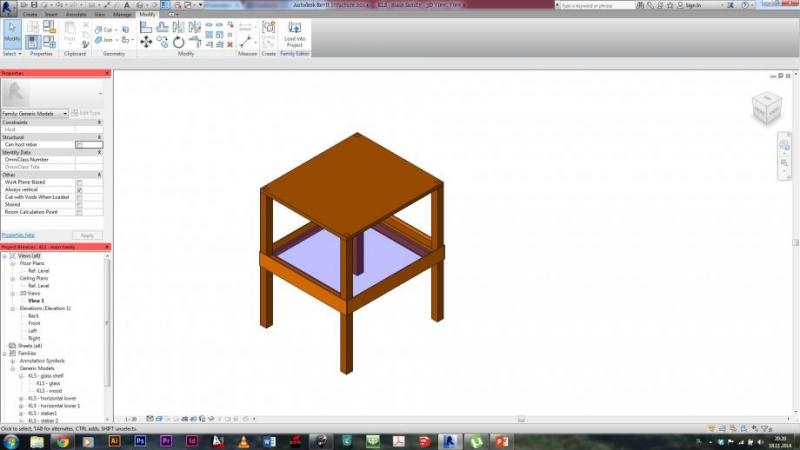
22. The last part of my model was the horizontal plane for my table. The base was an extrusion - created as before. The only extra thing was to creat holes in this extrusion and set parameters, so that the table would be easily changable in the main family:
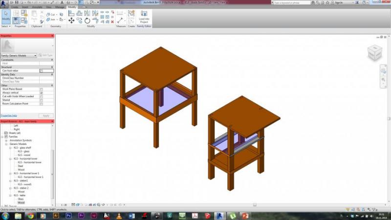
23. So, when this last part was imported into main family and after adjusting parameters, my table looked like this:
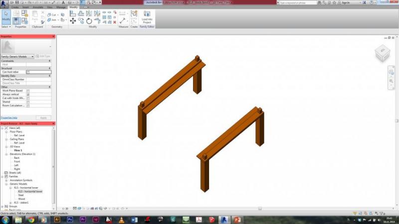
I was little playing around than with all parts, that I have created, and I made another object. I think, there are actually a lot more options how to put things together, like this:
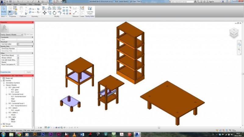
And some extra variations, created from the parts, that were imported into main family. They are just joined in different ways and with different values of parameters:

Commenti
StefanoConverso
Mar, 18/11/2014 - 14:22
Collegamento permanente
Unfinished? And a suggestion based on Scarpa
Hi Klemen,
we wait for commenting, since your post look unfinished.
For example, there are no variable components, only standard (correctly tectonic, though).
Is it correct? Will you update it?
Let us know!
S.C.
p.s.
Only one question: the horizontal pieces that link the table parts, how you imagine
them connected? Are they glued? Or visible screws?
For you, an image from a beautiful furniture series designed by Carlo Scarpa for Manlio Capitolo's classroom, in Venice.
It's a beautiful and somehow "variable" system. Different "doubly layered" pieces based on the same base elements, variated.
Klemen Stegu
Mar, 18/11/2014 - 21:43
Collegamento permanente
Finished
Now it is as I imagined it to be...
StefanoConverso
Mer, 19/11/2014 - 10:54
Collegamento permanente
More Variations
Hi Klemen,
I think we need to see more variations of your piece.
Also, while top with legs is clearly connected (and we can see the joint from top, is that that you wanted?
It is still not clear how you assemble the sides.
Please show it better if you can.
Good work though for now,
S.C.
Klemen Stegu
Mer, 19/11/2014 - 19:13
Collegamento permanente
Connections
Yes, I actually wanted, that it is seen, that the top is connected with legs, because this is actually meant to be the only place, which would show that the model is made out of multiple parts.
The sides are glued to the shelf-holders on the sides, so that no joints are seen.
I will do more variations and upload it as soon as i can.
Thank you for comments