


passaggio coperto
Il design del profilo nasce dall'idea di creare un ponte che è stato in grado di modificare in modo parametrico lungo la sua sequenza. Per questo creare una nuova famiglia (metric generic model) e proiettare una serie di piani di riferimento in cui il profilo del design.
E selezionato alla visualizzazione profilo altimetrico, e dimensionato spessori, in quanto questi saranno quelli che andranno in base ai parametri cambiano.
L'idea principale del progetto è che tutti i parametri sono correlati tra loro. Ciò significa che quando si modifica una dimensione della figura, gli altri spessori anche state modificate. Ciò si ottiene con l'aggiunta di poche formule che le relazioni con altri parametri della tabella di parametri. Per questo ho collegato gli spessori e le lunghezze del profilo con uno spessore specifico (B).
Ho creato un nuovo file in cui ho esportato il mio modello. (LOAD INTO PROJECT)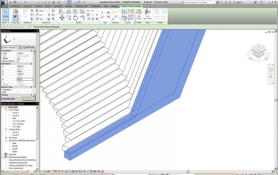
Ciò significava che il profilo da modificare deficiancias presente disegno. Quindi prendere la decisione di trasformare il modello per l'uso modificiar. Mantenere le definizioni dei parametri previamentente definito.
Il modello corrisponde ad un passaggio più coperta, che verrà modificato in funzione dello spessore del percorso, mentre il più alto è il mittente, maggiore sarà il profilo della piattaforma e più ampia sarà il profilo laterale.
Con la copia strumento che moltiplicato il profilo lungo un asse e hanno trasformato alcuni elementi per generare più profilo di movimento.
Ho selezionato ogni profilo e ho modificato un parametro (B) che ha fatto l'inversione di ogni figura.
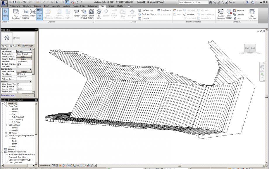
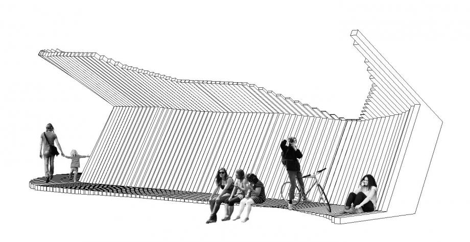
Il prototipo può essere pensato come mobili pendio, un percorso sulla collina e uno spazio urbano coperto.

Commenti
Manuel Andrè Bo...
Mer, 12/11/2014 - 15:36
Collegamento permanente
descrivere più passaggi
ciao Alejandro,
dovresti descrivere maggiormente i vari passaggi che fai per creare il tuo modulo. come fai a creare un volume estruso? dove trovi il comando? hai usato piani di riferimento? perchè? hai allineato la figura? bloccato gli allineamenti? come fai ad assegnare un parametro? tieni conto che chi legge il tuo post al momento non conosce nulla di Revit, devi scrivere un post in grado di aiutare chiunque passo passo a realizzare un modello come il tuo.
se hai difficoltà a scrivere in italiano puoi scrivere in Inglese, forse è anche meglio
Cristiano Piagn...
Mer, 12/11/2014 - 22:00
Collegamento permanente
interessante
Ciao,
concordo con Manuel. L'effetto finale del tuo progetto è molto interessante e non banale, quindi merita una descrizione più dettagliata e degli approfondimenti.
Complimenti per la media image.
valerio marracino
Ven, 14/11/2014 - 10:17
Collegamento permanente
Copia moltiplicato lungo un asse!
Ciao, trovo molto interessante il tuo progetto, io sto cercando di fare una cosa similie pero non riesco a compiare il mio oggetto lungo un asse. Volevo chiederti come hai fatto?
Grazie!
StefanoConverso
Ven, 14/11/2014 - 11:07
Collegamento permanente
In questa fase la variazione è manuale
ma in ogni caso domanda ottima!
Evidenzia una lacuna nel post, il post deve essere chiaro e replicabile da altri!
Fai una integrazione Alejandro!
Alejandro Saldias
Mer, 19/11/2014 - 11:13
Collegamento permanente
correction covered walkway project
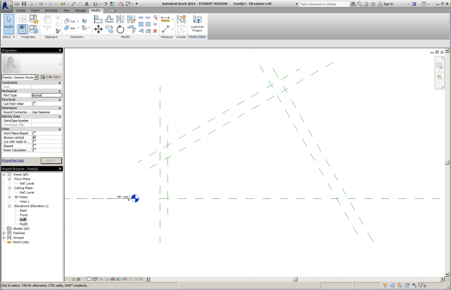
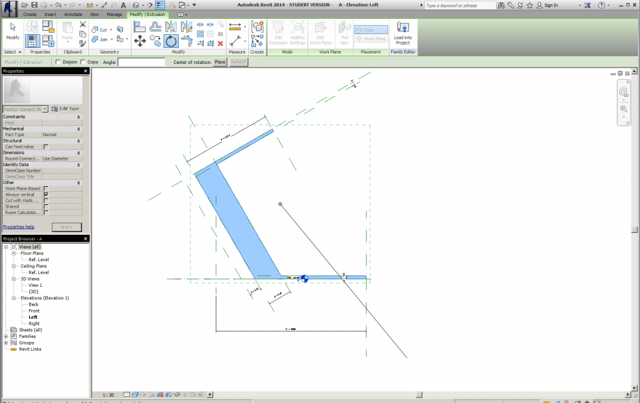
First you select NEW FAMILY, and then selected templates METRIC GENERIC MODEL
Then in the template, a left side in the PROJECT BROWSER box, I press LEFT on the elevation.
The object design it will be a profile in elevation that will go according to the necessity of repeating the geography where it is formally required, it will be necessary to work with reference planes.
Now let's CREATE / MODEL LINE to draw our profile on the reference planes (RP)
We click on MODIFY / ALIGN to close the lines with reference planes. Select the plane and then the line. then we click on the padlock.
Repeat the exercise with all the lines of our object and close all locks.
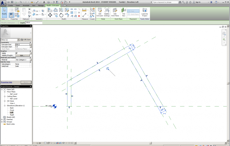
Now click on CREATE / EXTRUSION, we draw our object again and press the green button on top (FINISH EDIT MODE)
press the green button on top (FINISH EDIT MODE)
We return to our object align with the reference planes as in the previous step. CREATE / ALIGN, select each line and together with the reference planes. pressed all locks again
Now let MODIFY / DIMENSION / ALIGNED to give dimensions to our object.
This will help us assign each parameter a different dimension.
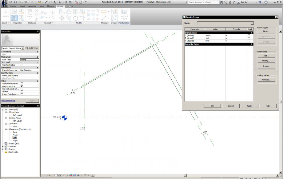
Now select a dimension and then on top (LABEL) pressed the gray square and then we click on ADD PARAMETER.
A dialog will open properties parameters, here we assign a name and click on INSTANCE, then we are OK.
Repeat the same procedure with all our dimensions, in this case I have assigned parameters A, B, C, D. These parameters represent the length of the profile (cover), the width of the profile (wall thickness) and height profile (path)
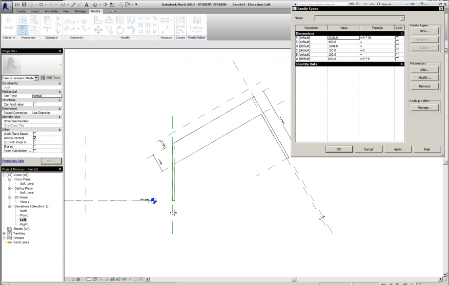
It is important to relate all the parameters for one modification after modification means all our object, that is mediating the definition of formulas in the CREATE / FAMILY TYPES table. In this case all the parameters are entered in function of the parameter C.
We can determine the thickness of our object in the picture PROPERTIES. EXTRUSION END / STAR EXTRUSION. Here we modify our thick and give 100
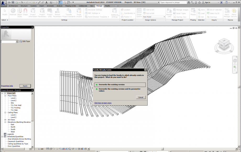
We keep our project and opened another new family with METRIC GENERIC MODEL template.
We keep our new family, we assign a name, and return to our FIRS OBJECT.
In our family we click on the MODIFY / LOAD INTO PROJECT button
The new family will open and click on any point in space. Now we have our object into a new family and we can copy it and create our final model.
When we select our object we can see in the Properties box located at the side of our parameters are shown,
but we can only change the parameter C.
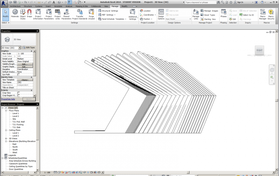
Now proceed to copy and multiply and we will do our DESIGN with ARRAY command, this way we can multiply LINEAR or RADIAL way and anyway the desired quantity
In the box next to our object we define the distance separations tenra other model.
in NUMBER we define the number of items we want.
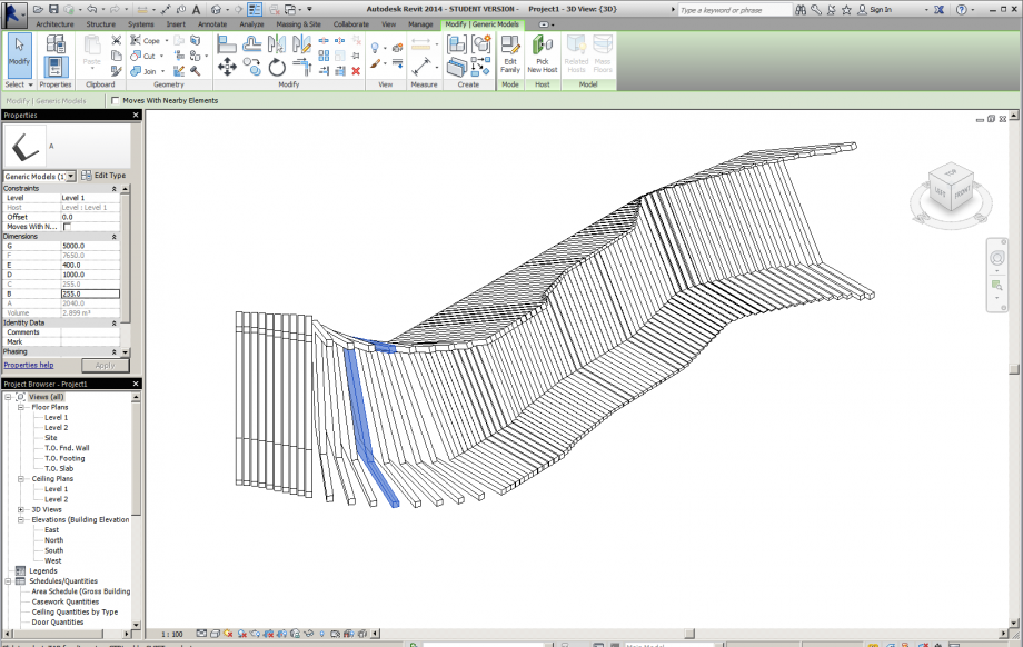
Our model has increased linearly but has remained as a block to manually modify each element is necessary ungroup models. For this we select and high in the UNGROUP seleecionamos MODIFY button.
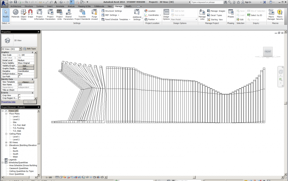
Now we can freely modify our models to select this one and next, in the Properties box, where we show the parameters, we will change the parameter C, this will make the modification of elemeto generated. To generate the final shape each element must be selected one by one. It is also possible to give our curves with the array element, RADIAL command. .
Finally it is possible to create several possibilities with this morphology, conceived as a path leading into the hillside. as a lookout or street furniture.
Manuel Andrè Bo...
Mer, 19/11/2014 - 18:00
Collegamento permanente
good explaination
thanks Alejandro, it's not only a good explaination about your design process but also a smart way to design curved shapes just using manual controls