


Goccia
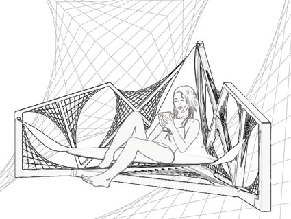
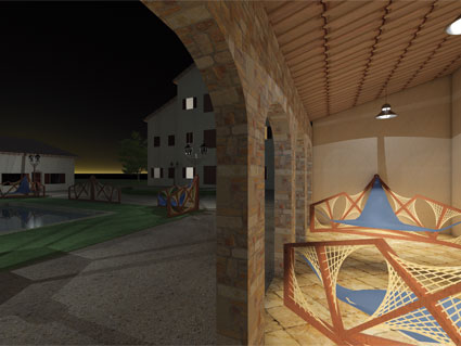
For the delivery 2 I thought to get inspiration from the next design (it is a my idea of some years ago)
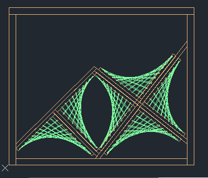
I found my old drawings, that I did with autocad, and I begin to think how to do my project. So I do a new sketch with autocad.
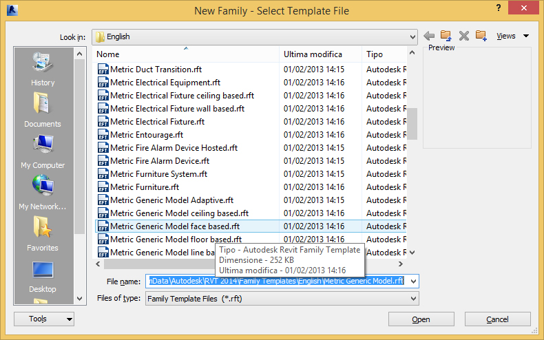
Then I open Revit and choose the family template “Metric Generic Model face based”
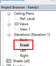
Now Select Front View
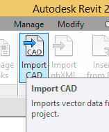
Import sketch made with autocad
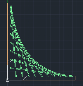
With the menu Insert -> Import CAD
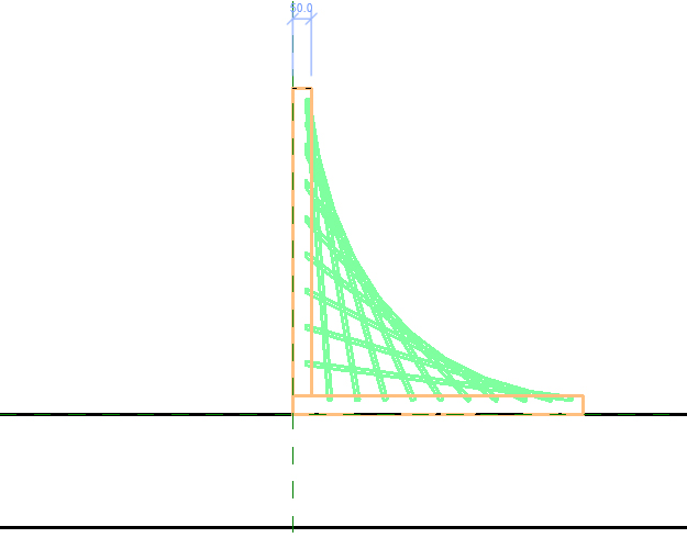
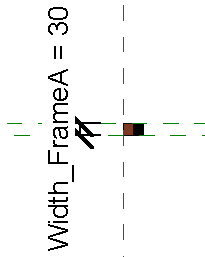
Then move it as shown in the next image
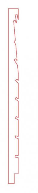
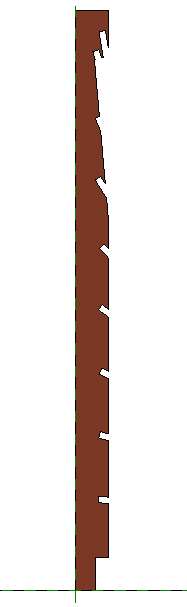
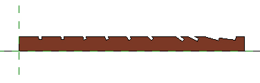
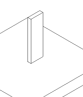
Do a new extrusion to construct the frame from the next profile
Create the parameter Width_FrameA
Now create the parameter Material (see Type parameter in this blog)
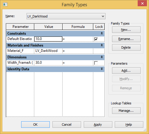
Now there is the object LV_FrameA
Create the other part of the frame in the same way; it is LV_FrameB
Create the rods like another parametric object beginning from the template “metric Generic Model face based”.
It is the family: LV_cues
This family have the next parameters (to do this see how is made “Portale” in this blog):
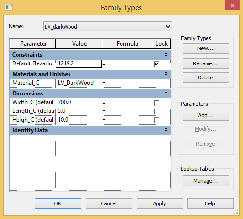
Do a new family from template “Metric Generic Model face based” LV_dPattern where assemble the families LV_FrameA, LV_FrameB and LV_cues.
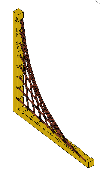
To make sure that the family is designed to move as a single object, bound the faces as shown below (for example, takes only a part but all the rods are placed in the same way)
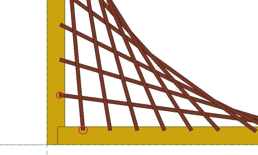
The rods are locked each other
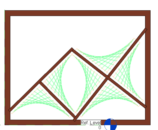
Create the family “LV_BigFrame”. Import the autocad sketch. Create the frame.
Create a new family from “Metric Generic Model” to do the final object.
Import the autocad sketch in Front View.
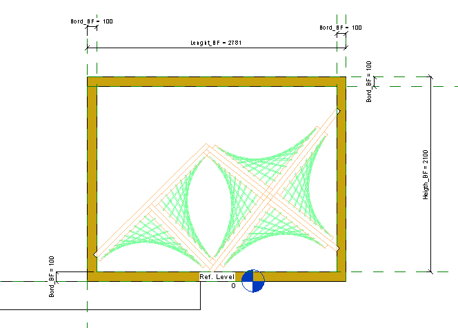
Load the family “LV_Bigframe” in ref_level. Switch in Front View again or in 3d View. Load the family "LV_cues" and create the necessary rods and link them with the family "LV_Bigframe". See below:
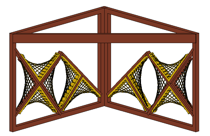
Insert the family “LV_dPattern” and link it to the frame as shown in the next image:
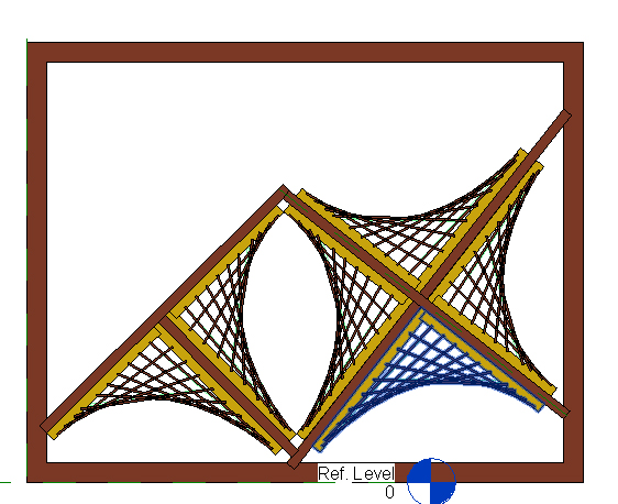
Construct another wall and assemble them as shown below:
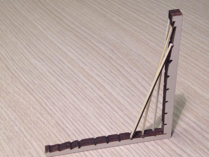
Lab test:
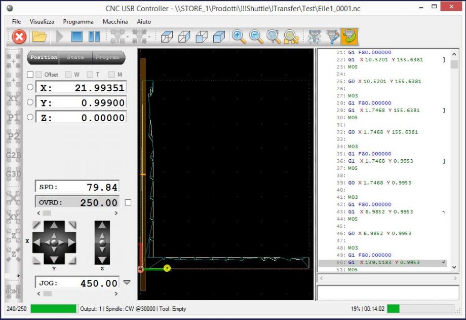
exported the LV_frame in dxf format (autocad 2010), Then open it in CNC USB Controller.
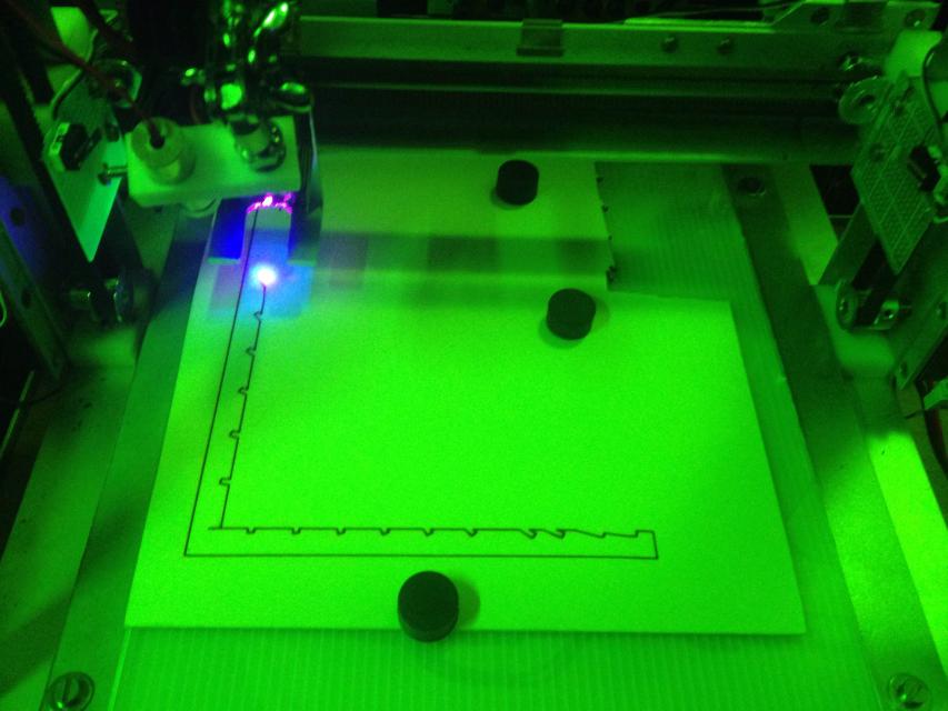
Run the program on laser cutter (home made):
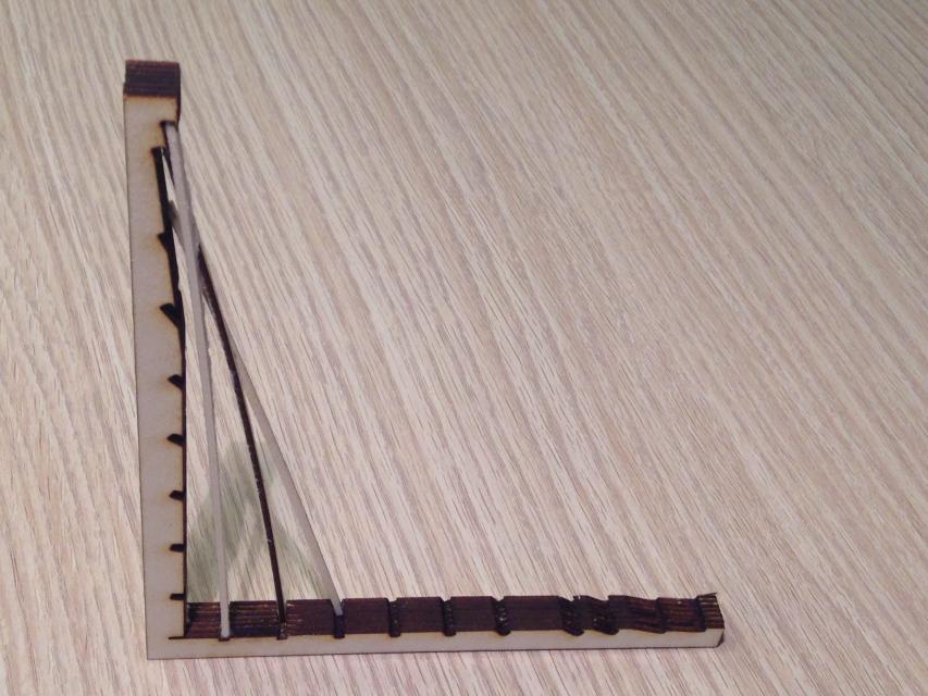
This object is in woodpaper (see below):
Commenti
StefanoConverso
Mar, 18/11/2014 - 17:16
Collegamento permanente
Laura, very nice!
You "closed the circle", and fabricated it!
Of course the model shows a problem of interference between components, but it might also be a chance to evolve your original idea, and have larger supports, if they are not connected by wires... fabrication could inform the initial design and push it to an evolution.
But definitely well done in any case, for now!
Manuel Andrè Bo...
Mer, 19/11/2014 - 19:40
Collegamento permanente
great work
really a good work Laura, you showed how design process can feeds itself by sharing information between differents software, but also, as already said the professor,"...fabrication could inform the initial design and push it to an evolution"
laura.vellucci
Mer, 26/11/2014 - 23:46
Collegamento permanente
Goccia 2
Goccia 2
Create a new family from the tamplate “Metric Generic Model face based”.
Move to the front view
Create reference Planes for the parameters that are H_dima, L_dima, Wdima, T_dima and create a new extrusion
Select from the menu the icon Void Form -> void extrusion
Do the holes and create the parameter Dima_RaHole
In the same way do the holes in the other side of the dima
Add a new parameter for the extrusion of holes .
All the parameters created now are Parameters of Istance , now create the Parameter “Material” like a type parameter.
Create a new family from the tamplate “Metric Generic Model face based”.
Draw a inclined referent plane and create parameters as shown next (Attention: the parameter "Ang_Splints" is created by function atan(Hsplints/Lsplints)
Now create other “Reference Plane” and the "Extrusion" as shown next
Then create the hole in the right view as shown next
And the other hole in "reference level view"