Consegna 2 - Parametric Bus Stop
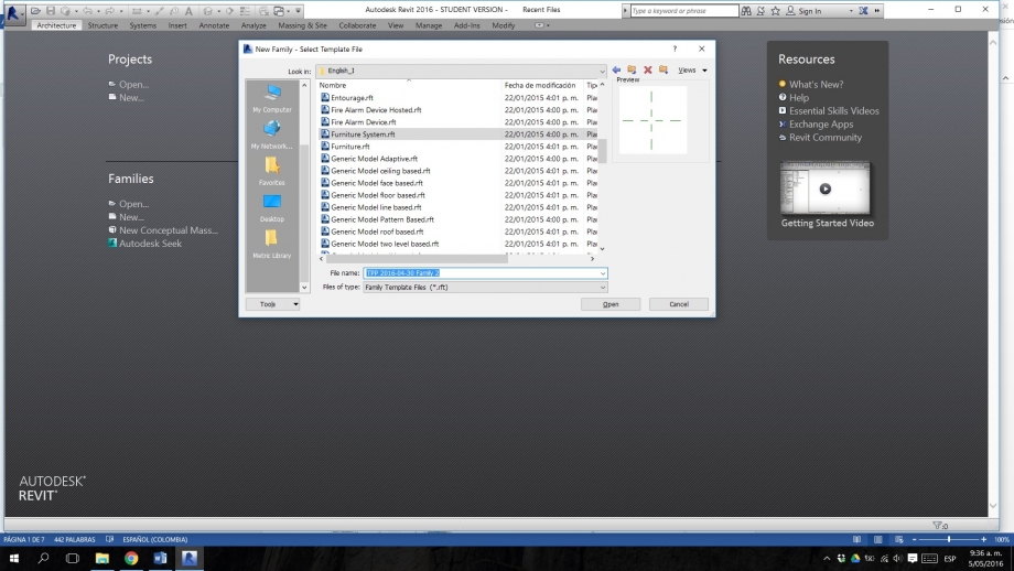
Step 1. Families – New – Furniture System.rft layout.
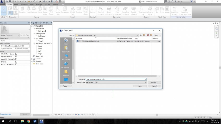
Step 2. Save your new family with a specific name so you can be able to identify it later.
Step 3. Create – Reference plane (this plane will be the edge’s axis of your object).
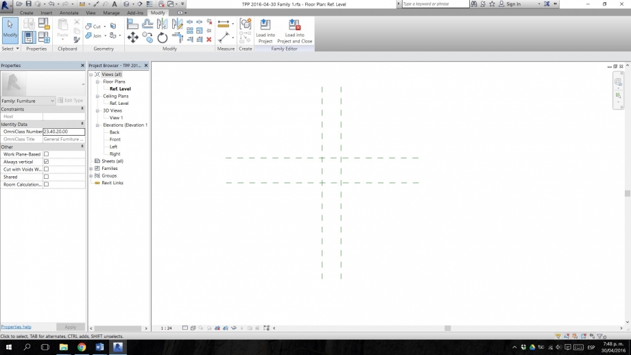
Step 4. Annotate – Aligned – Select the reference plane you have created, and quote it in relation with the X or Y axes of the layout (the intersection between these two, is going to be the origin point 0, 0 of your family).
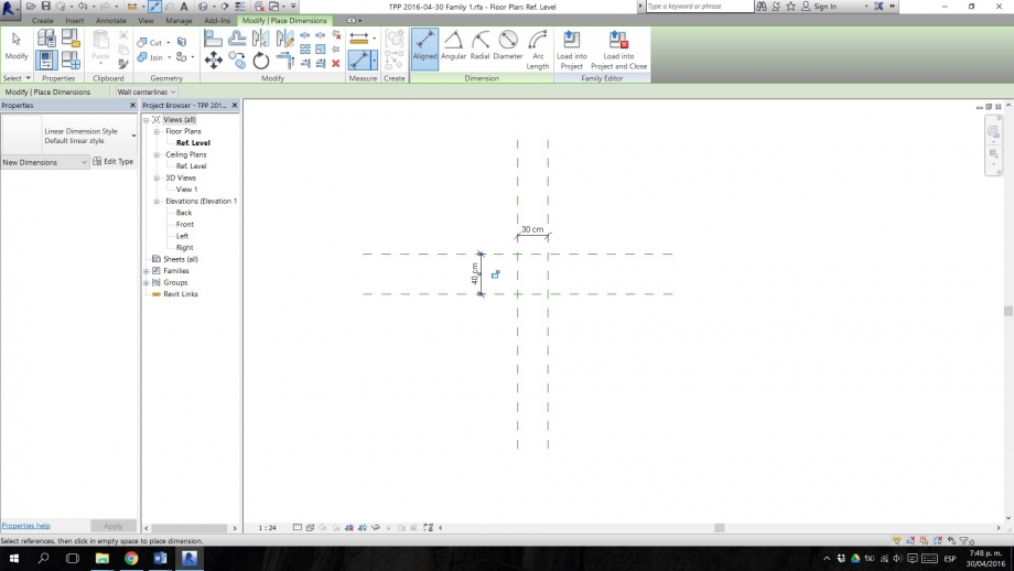
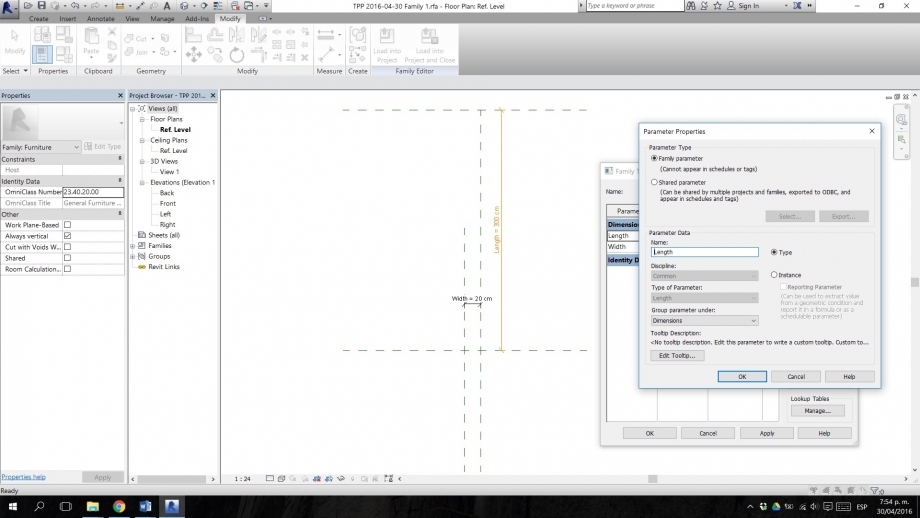
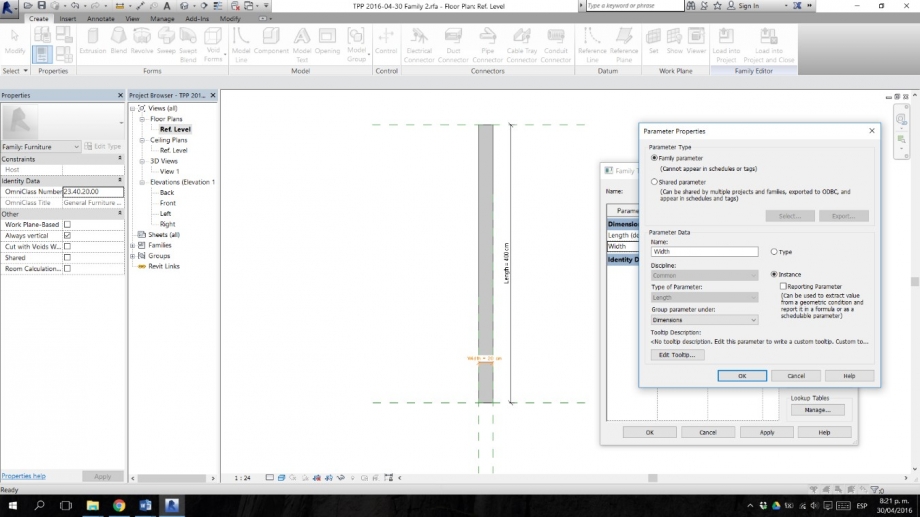
Step 5. Create parameter. Select the quote of one of the reference planes you have created (parallel to the y-axis for width, parallel to the x-axis for length), go to the label option on the top of your window, and add a type parameter. Name it with comprehensible names so you can remind these parameters later.
Step 6. Create a rectangular extrusion.
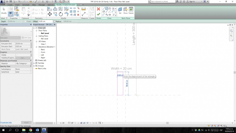
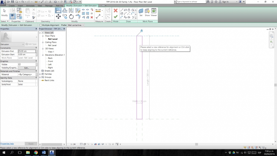
Step 7. Edit the extrusion. With the align tool, align each of the planes of the extrusion you created, to the x and y axes of the model. Then to the reference planes named Length and Width. Remember to lock them. This will make your extrusion, variable according to these parameters.
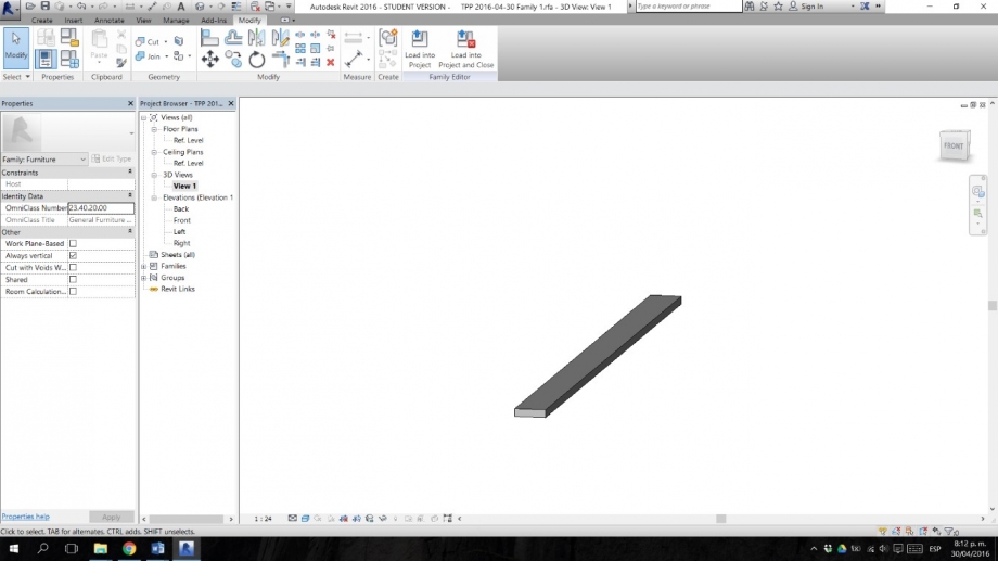
Step 8. The result, after making some tests of changing dimension on the parameters of our family, would be something like this. This actual piece measures 400 cms of length, by 20 cms of width, and an extrusion of 5 cms, which indicates the object’s thickness.
Step 9. We have our first family, called Family 1 as we named it in the beginning. This family can only be controlled by type parameters. Now we are going to create a new family, made up of instance parameters. For this, we are going to save the same family but this time call it Family 2. We modify the parameters and make them instance parameters, as in the image.
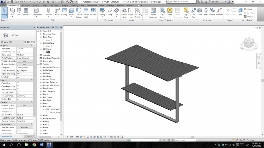
Step 10. Now we have the two types of families of which our object is going to be composed. We open a New Project, and import on it our Family 1 from type parameters. The Family 1 objects are going to be used to create the non-variable parts of our object, as in this case, the structure of our bus stop. We can see it in the image.
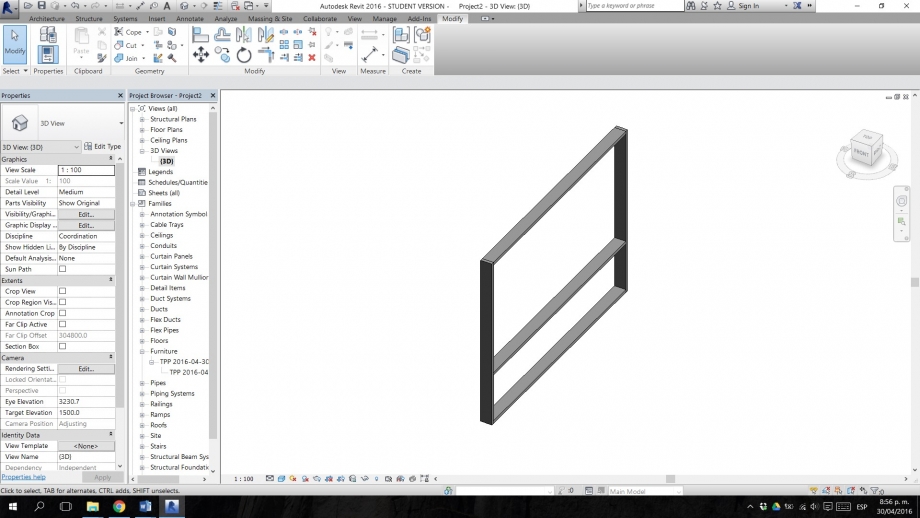
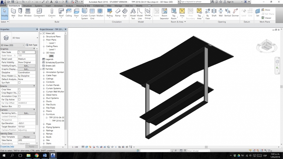
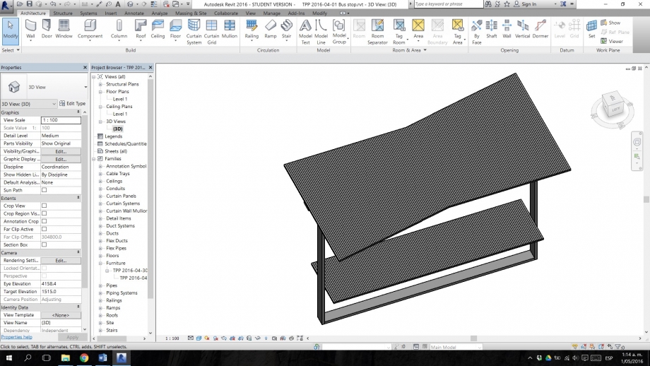
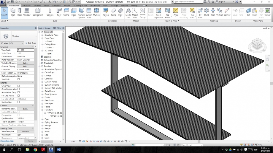
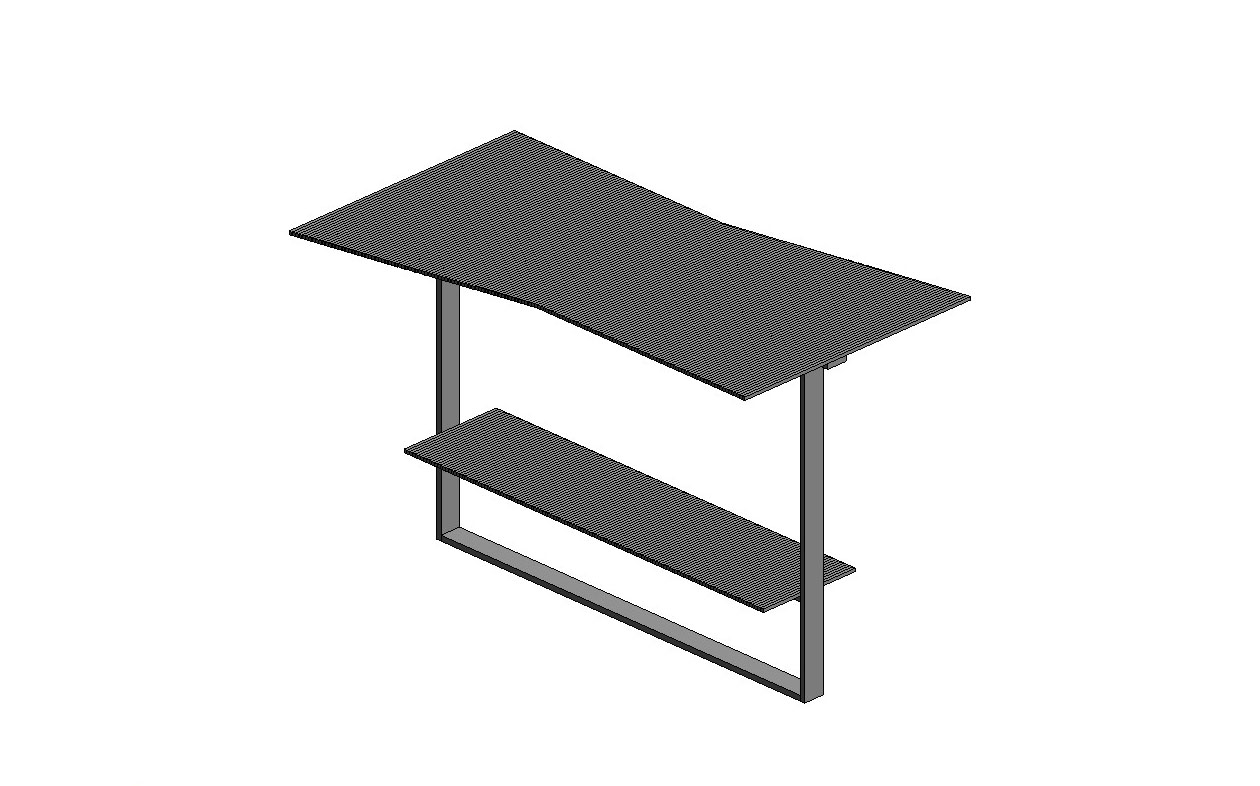
Step 11. On the other hand, we load our Family 2 objects, the ones that are modifiable through controllable parameters of length, width and depth. The instance parameters are going to be used to create the variable objects, the ones we want to control, as the ceiling or even the chair of our bus stop. The result would be something similar to this.