


Progettazione Parametrica di un tavolo
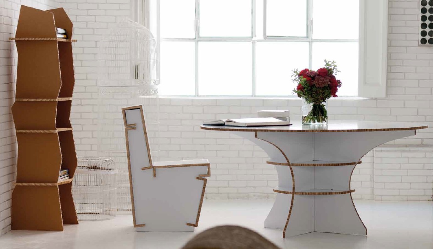
I decided to design the table shown in the headline picture. It's a table built in cardboard's pieces assembled interlocking.
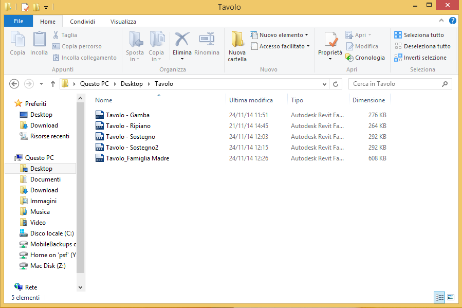
I created a folder on my desktop in order to have all the pieces of my table in one place.
I started to design the table opening a new family, this family will be my "Tavolo - famiglia madre" (table - mother family). This is the main file where i'll be assembling all the pieces of the object. I opened the new family, and choose GENERIC METRIC MODEL.
First of all I changed the units of the file in in meters. It's important to set the dimension of the object parametrically. In order to do so I used the command REFERENCE PLANE, (p.1) and locked the dimension. I did so in the plant and front view. (p.1 p.2)
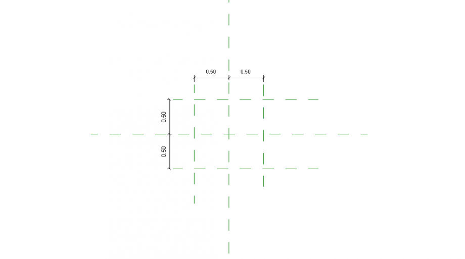 p.1
p.1
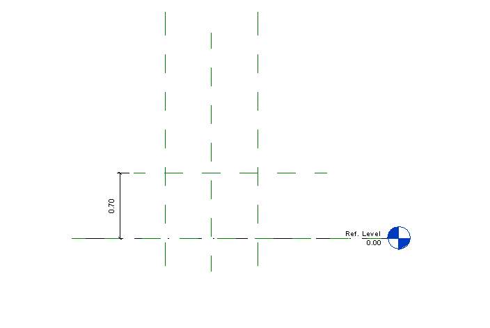 p.2
p.2
After I set theReference pPlane I added the parameter using the command FAMILY TYPES. (p.3) With this command I was able to create parameter to assign to each dimension. When I create the parameters e.g. lunghezza, profondità their value was 0.00 that's because they weren't assigned to any object. After they were assigned to an object the value changed (p.4)
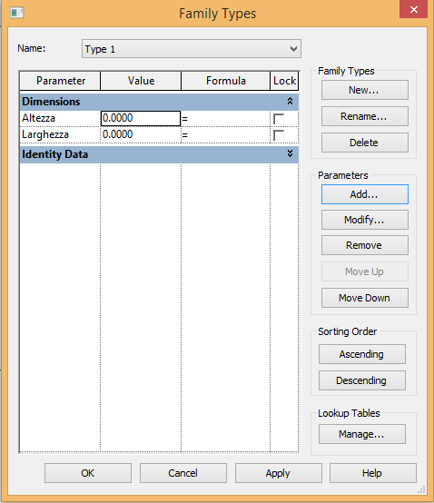 p.3
p.3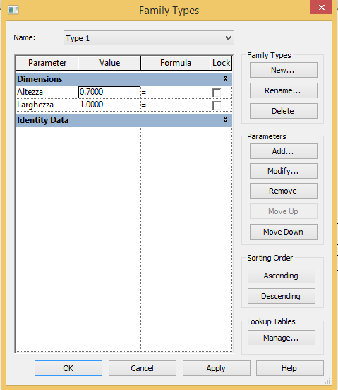 p.4
p.4
After this I saved my document in the folder "Table". Every object in the folder will be named "Tavolo - x" in order to have everything organized and the metadata well defined.
Now I have to design the pieces of the table. The mother family is composed by four sub-family: Tavolo - Gamba, Tavolo - Ripiano, Tavolo - Sostegno e Tavolo - Sostegno2. (p.5)
I'll explain the constroctruction of only one of this pieces (Tavolo - Ripiano) since the modus operandi is always the same.
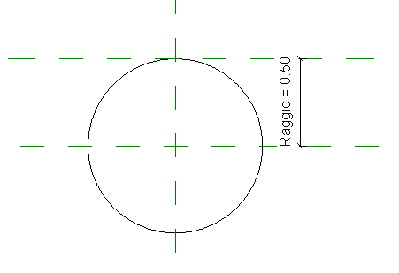
I used the command OPEN, NEW FAMILY, GENERIC METRIC MODEL. As for the mother family I set the main dimension with the command REFERENCE PLANE and add a parameter to each dimension. I used the command CREATE, EXTRUSION and draw a circle. The ray of the circle is locked to the reference plane so that when the parameter of the reference plane changes the lenght of the ray changes as well. (p.6) I did so also for the thickness of the shelf. (p.7)
 p.6
p.6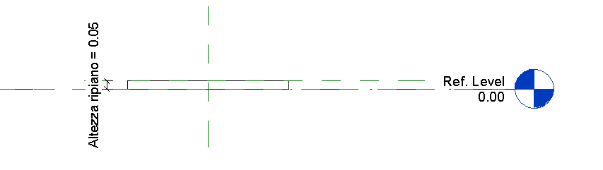 p.7
p.7
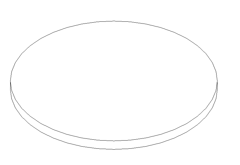
After this my drawing of this part is complete. (p.8)
 p.8
p.8
The other parts are: Tavolo - Gamba (p.9), Tavolo - Sostegno (p.10) e Tavolo - Sostegno2
 p.9
p.9 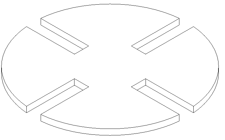 p.10
p.10
It's important to say that in order to design the joints of the legs and the crutch (p9, p.10) I used the command VOID EXTRUSION. This allowed me to subtract matter to the main object and create a void.
After this I opened again my mother family in order to combined all the pieces of the table. The shelf is glued to the legs of the tabels. The legs are held togheter by the crutch that are interlocked. I used the command LOAD FAMILY and then PLACE COMPONENT in order to virtually build the table.
I loaded the family "Tavolo - Gamba" four times. and then put it all togheter. (p.11,p.12,p.13)
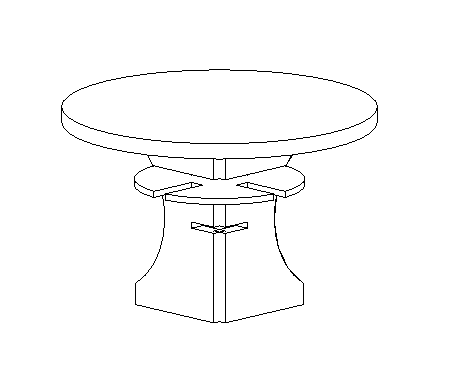 p.11
p.11
 p.12
p.12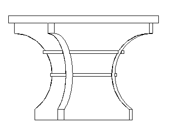 p.13
p.13
Commenti
Manuel Andrè Bo...
Mar, 25/11/2014 - 13:18
Collegamento permanente
Great Organization
hi Matteo,
Good explaination of your work, i really appreciated your files organization, as well as the way you organized pictures and steps. Did you already use Revit before ? (just a my curiosity).
Wich kind of family did you create for the different parts of the table? for the Delivery 2 we tryed to focus on generec model face based. You should try to integrate this technic into your assembly process. Try also to add Material parameters.
Last but not least....we need project variations! is useless create parameters without making variations :)
good work
Matteo Molinari
Mar, 25/11/2014 - 14:51
Collegamento permanente
Hi Manuel,
Hi Manuel,
No, I never used Revit before, it's my first try. I used metric generic model, not face based. I'm going to implement this kind of family and parameters variation in a new post in a few days.
Matteo Molinari
Gio, 27/11/2014 - 23:09
Collegamento permanente
New parametric object, with parameters and faced based model
With this object I added the use of metric generic model faced based family and parameters.
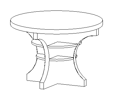
I kept the theme of a cardboard made object, this time designing in revit a coffe table. The original design was for a table, I adapted it to my needs. (p.1)
This table is formed by three sub-family, that i reapet two times. So the families are: Tavolino - Famiglia Madre, Tavolino - Componente 1, Tavolino - Componente 2, Tavolino - Componente 3
As I did for the previous design I created a folder named "tavolino" in which I placed the mother family and the sub families (p.2)
I created the mother family with a GENERIC METRIC MODEL FACED BASED, in which through the REFERENCE PLANE I gave the main dimension of the coffe table. Hight and width (p.3 p.4)
Then I created the sub-families as for the mother family I used a GENERIC METRIC MODEL FACEB BASED of the component of the table. I used the command EXTRUSION. Each component is a cilinder with a different ray in order to give movement to the design. It's important to notice that with this kind of family when is imported in the mother family you have to place it on a surface, the surface where is placed influences the way the object can be moved in the mother family. This time I added a parameter to the ray of the circled, I called it RAGGIO to keep it simple. Following the three components with each parameter (p.5,p.6,p.7)
Now after I have finished with the components of the table and added a parameter to each one of them it's time to put it in the mother family.
In order to place it in the correct way I started from the bottom up. I used a REFERENCE PLANE and the command ALIGN in order to have all the centers of the extruded cilinder bloked in one place. (p.8,p.9)
This coffe table has maximum diameter of 1 meter, now using the parameters I can create a coffe table of every dimension I want. For example I can have a maxium diameter of 2 meter and consquently the other 2 components will have a bigger diameter. To change the parameter I can simply double click on the family in the left side menu and a window with all the parameter will show up. (p.10)
Now I do the same things with the other two components and I have a different dimension coffe table but with the same design of the previous one. This was possible because I used the parameters. (p.11,p.12)
StefanoConverso
Ven, 28/11/2014 - 14:18
Collegamento permanente
Matteo, this reply would work better as new post, please do!
The same applies to others!