


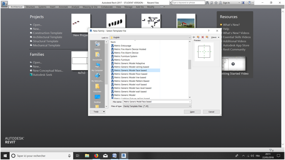
Consegna 4
I create the basic extrusion, going on extrusion and setting two reference planes, aligning the part to the ends of the default plans because this will be useful in the positioning. I assign the dimensions, which parameterize: Length : 2000 cm Width : 100 cm I gave 100 cm of thickness to this object.
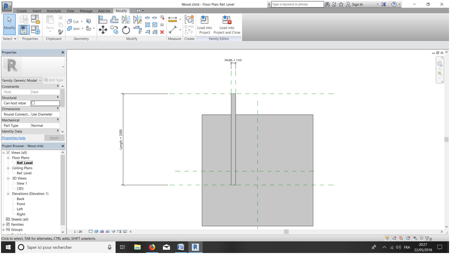
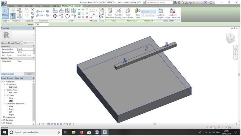
I create the buttonholes for the screws, helping me with reference planes for their positioning, which are located at 300cm from the edge of the object. After that , I did, extrusion > circle, I did it from the intersection center of the previously established reference planes and remaining inside the extrusion. Then, from properties > solid > void I could create an object that can pierce the previous one.
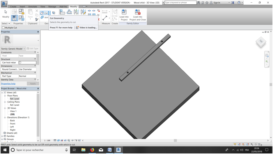
With the cut command, I select the two objects and create a void.
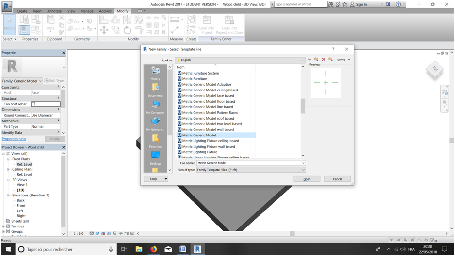
Now I create the "mother" part that will support the "child" object, starting from metric generic model.
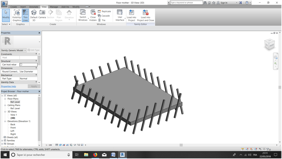
I created the extrusion and gave it the dimensions: Mother Width : 5000 cm Mother Length : 7000 cm
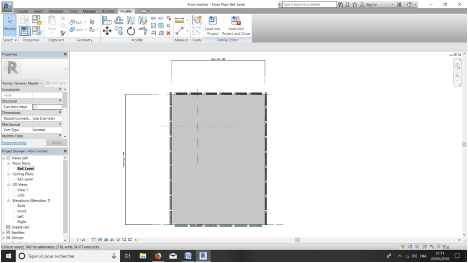
In the same file I created the beginning of the façade. The child object will be stick to this part after it.
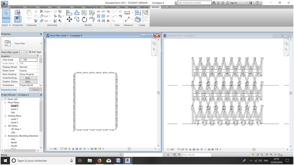
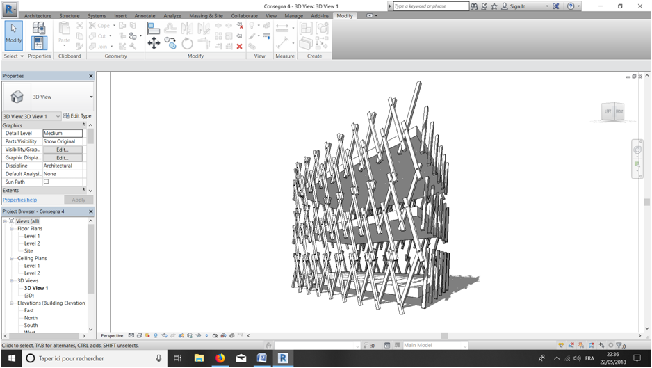
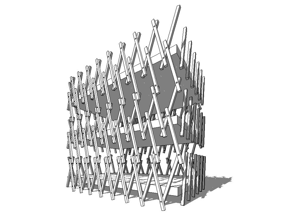
Here, after adding the child file, we can see on the façade my try to bond the different floors with the child object.
With one of the rendering method, I added some shadows.
Commenti
StefanoConverso
Ven, 25/05/2018 - 16:45
Collegamento permanente
Put the process IN the post
Dear Alexis,
Nice experiment, it seems to take advantage of our "repetition routines" (curtain wall)?
I suggest you to add the post content in the message, and not attached.
So we can comment your tectonic assembly.
Interesting concept. Do you want to develop it for the final project as well?