Facciata parametrica
Hi,
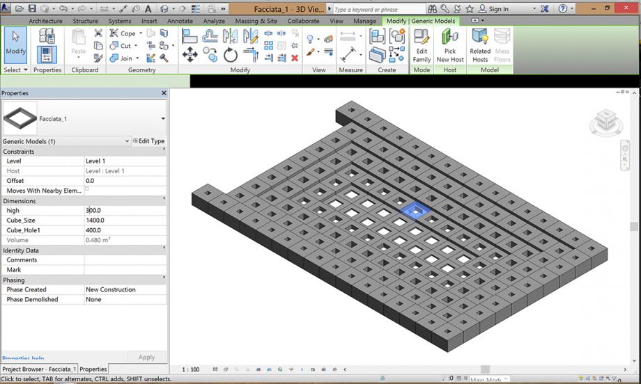
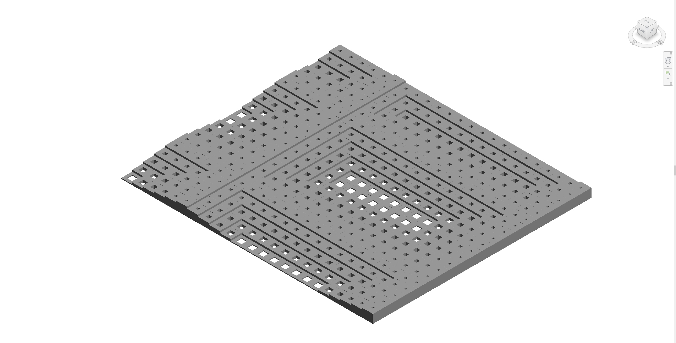
I tried to design a facade for a building which creates different areas of shadow and light based on an parametric element. The element is a cube with a whole which can be modified by parameters and also the hight can be changed. By that the facade can also interact with the space infront of the building.
My only problem is, that I couldn't find out how to rotate the facade in the three dimensions. That's why my facade is in the "wrong" level. It's presented in the horizontal level instead of the vertical..I read that I'm not able to rotate in 3D in the project file so that I have to change the family file. But I don't know how. Can anyone help me?
Greetings, Natalie
Add of the process 17.11.
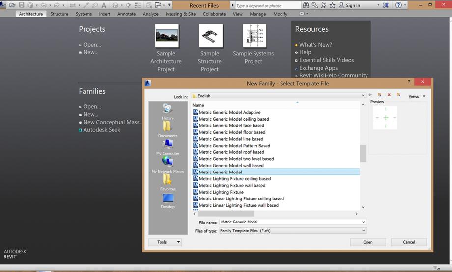
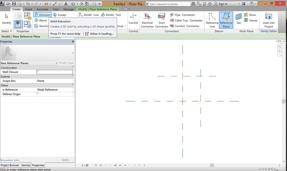
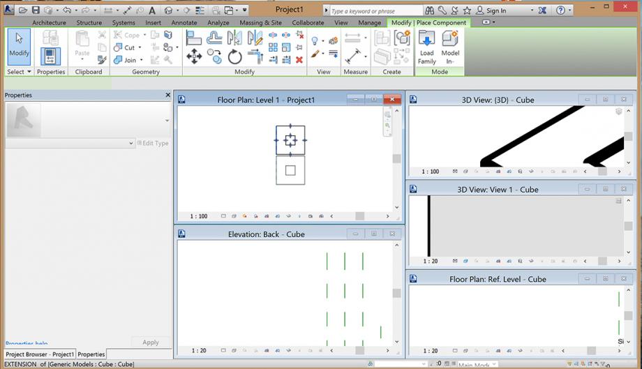
First I opened a new family file "Metric_Genetric_Model"
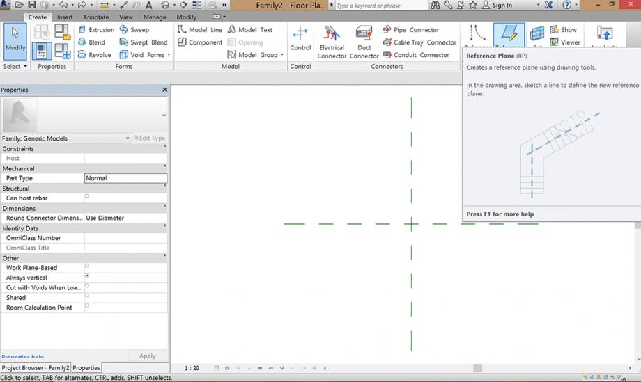
Then I selected the tool reference plan and added two of them
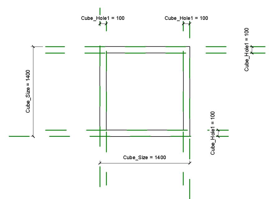
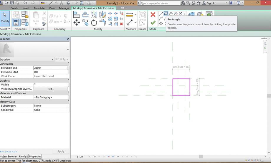
After that I selected the tool EXTRUSION to build a cube. First I created a "free" rectangle and then with the tool ALIGN while first choosing the reference plane and the the line of the retangle I modified the form of the cube.
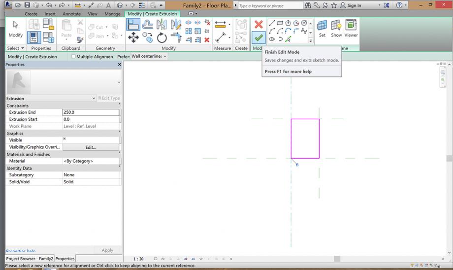
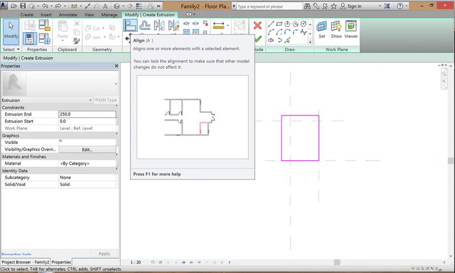 It is very important that you lock the relation of the lines after each step while using ALIGN and when you are done press green check
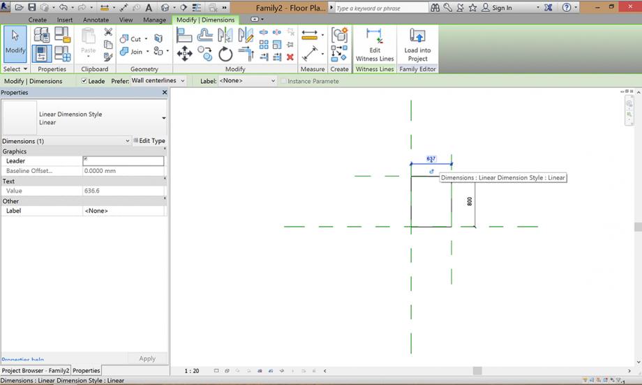
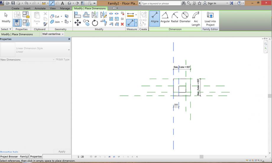
The next step is to add the quotes. While using the putton in the top with I selected always the reference planes for adding the quotes. The third click has to be in the middle of the quote to complete the action. I added quotes on both sides of the retangle.
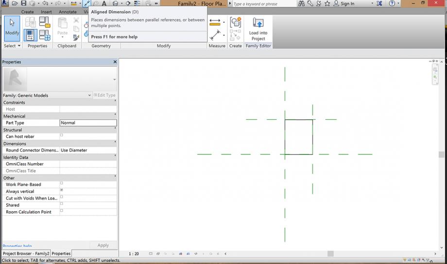
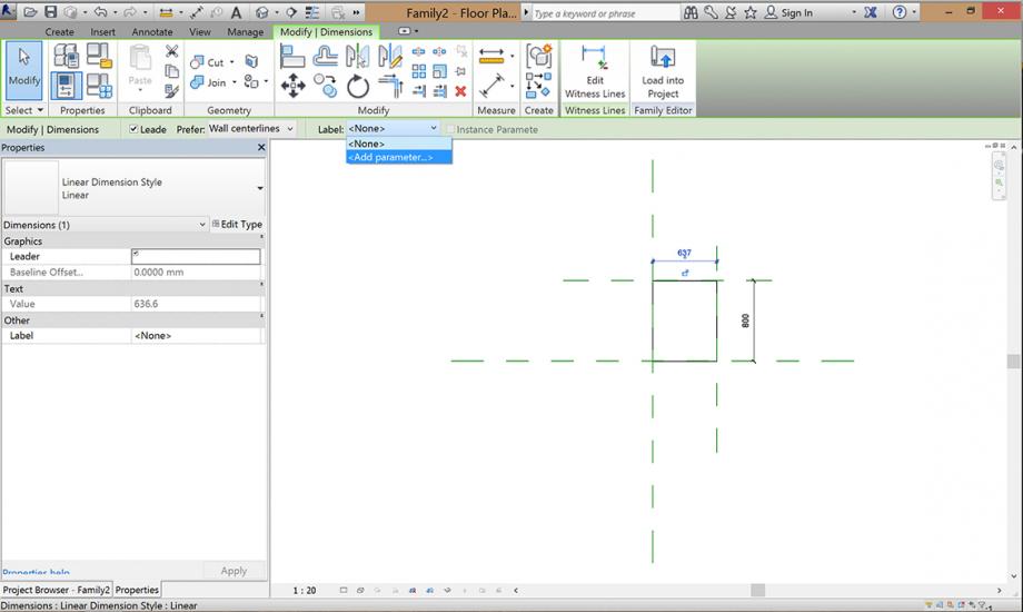
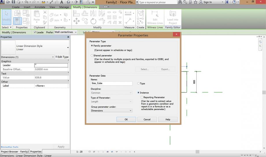
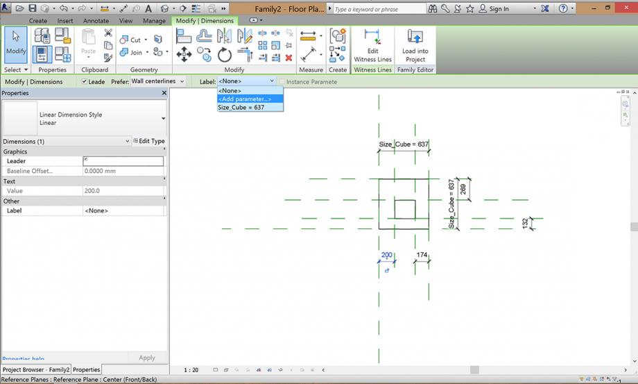
Now I've added my first parameter. In the green row while selecting a quote you see next to the word "Label" written the word "None". You can select this window and click an "add new parameter". In a new window you can create now your new parameter. You have to name it with a sense for your project and then select "Instance". Press OK and you have created your first parameter. I've added mine to both quotes so I can have automatically a quadrat which I can regulate with one parameter.
To create the hole in my cube after I had add 4 new reference planes, I clicked on "Edit Extrusion" und created the second retangle which I aligned also on the reference planes, locked the relation and than add one parameter for the regulation of the hole.
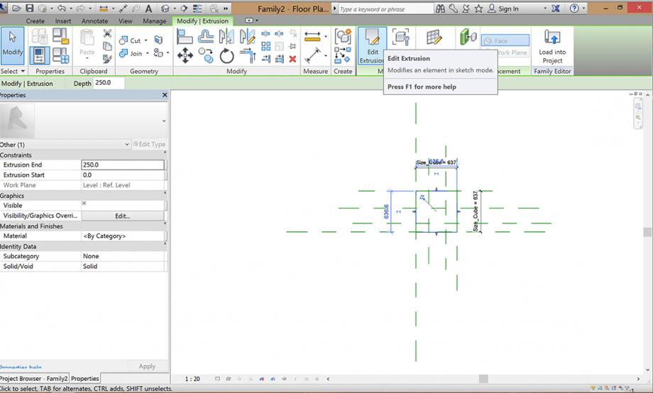
Now I chose a different view on the cube (Elevations - Back) and added one reference plane to create a parameter for the high of the cube. always aligned and locked.
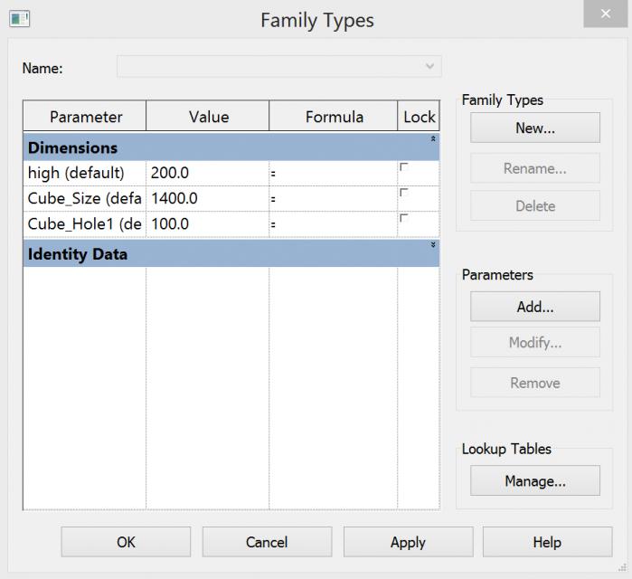
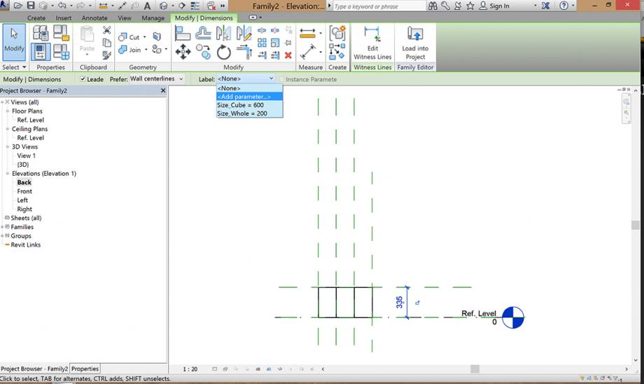 Now I can controll my parameters with clicking on Family types in the taskline and I am able to modify or create parameters.
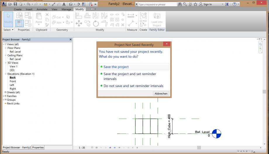
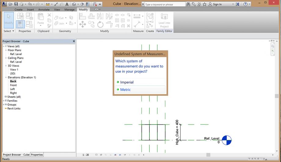
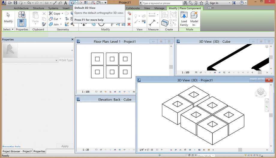
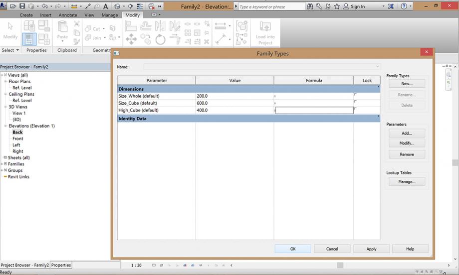 Next step: I created a new project as an metric one and then I can load, after saving the family the family in the project while click on "load into a project"
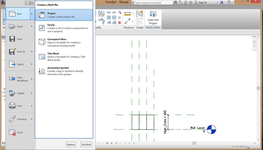
 Then I can as many cubes I want into the project and create my facade pattern. While clicking on a cube in the field of properties I can change the parameters of every cube and like this I created my facade. You can have a 3D view if you click on the House in the topline of the programm.
Commenti
StefanoConverso
Mer, 05/11/2014 - 17:26
Collegamento permanente
No process
Natalie,
you have to post the modeling process, possibly step by step,
otherwise we can't assign a C to your work, no matter how interesting it may look
the result, and it is interesting, but still, please update.
Process and Product must become one and the same.
No documentation, no luck
S.C.
Natalie Ruggiero
Mer, 12/11/2014 - 14:37
Collegamento permanente
Processo
Sorry I didn't know how to upload more Pictures.
So I started with a familyfile while creating a cube with the parameters of the hole, the size of the cube and the high of the cube. Than I put it in a projectfile and copied it a few times and changed the parameters and created this facade.
Hope I'm not to late. I'm very sorry.
Greetings, Natalie