


TRIANGULAR VARIABLE MODULES
In this second post I wanted to examine how to assemble a facade through the study of a base module that varies depending on solar radiation.
This facade was thought for the project carried out in the course of Laboratorio 2M. Now, in Laboratorio3M, the development of this casing is ongoing.
The main concept of the facade was to create a surface that could change according to the solar incidence on it. It is oriented south-west. At that time, we don’t knew how to use Revit or any software which could help us to control it to suit this parameter.
So the idea for this post is to take advantage of tools learned to satisfy this necessity.
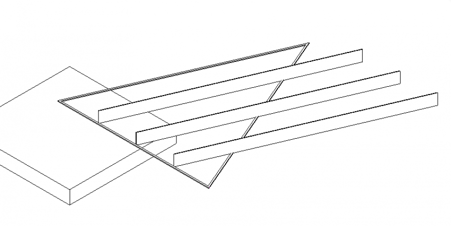
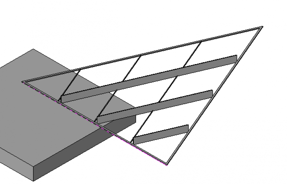
Approximately, the final result should be this one.
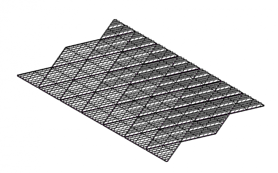
Substantially, the shading system is based on the bris soleil concept, trying to have an inner comfort for users, both visual and thermal.
Excuse me but I wasn’t able to create this facade vertically because I found some problem loading the “component face based” into the main family. I can’t move it vertically on the work plane because, as was said in class, it is fixed on the work plane. And I can’t load the same component two times in the same main family, as it already exist in the file. So, I create the facade reasoning by layer. The first one was the main structure, the second one was compound by the triangular modules.
The workflow to create the facade was:
PIPE
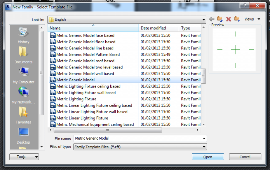
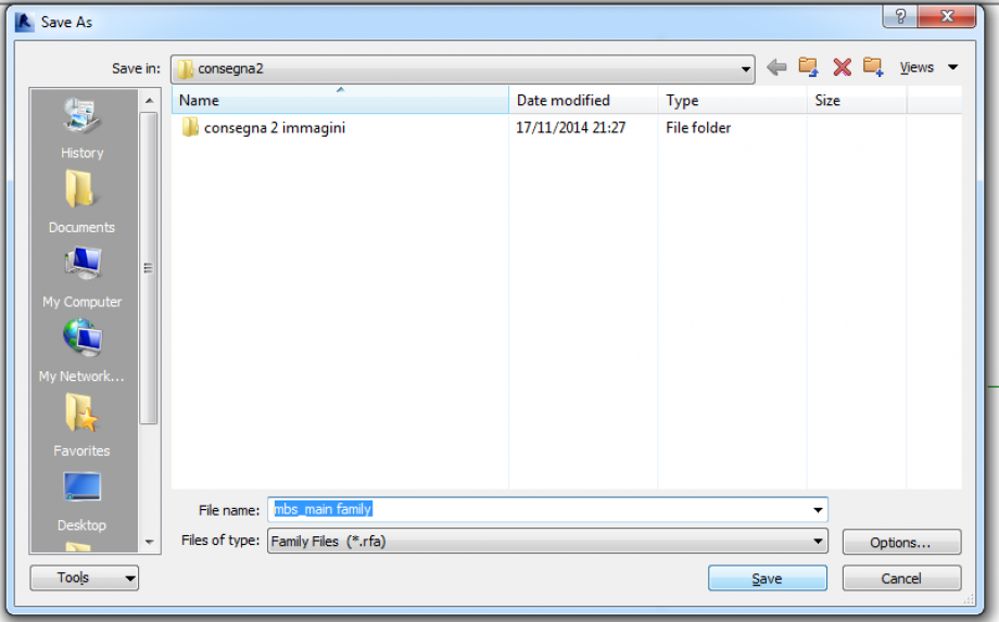
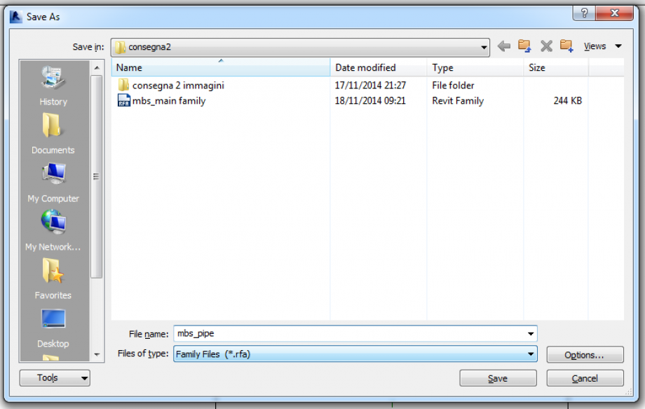
1. open a new file> Family> Metric Generic Model> Rename the file> mbs_main family (this file will be the place where I’ll assemble the facade)
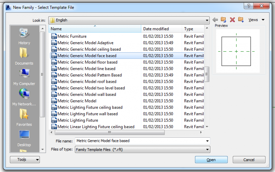
2. Create a new file> Family> Metric Generic Model Face Based> rename the file> mbs_xxx (xxx is for the name of the component that is shaped on it.) Face based is useful later when the component will loaded in the main family because in this way it could be “attached” on any surface and not only on the work place.
The main structure of the facade, the one where all modules are fixed, is a reticular structure. So the first step was to create the pipe as the base module of this structure.
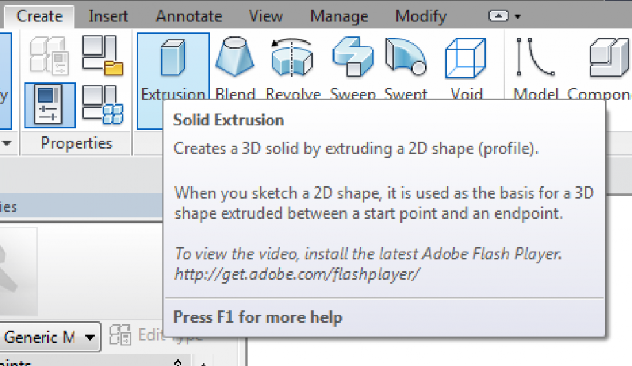
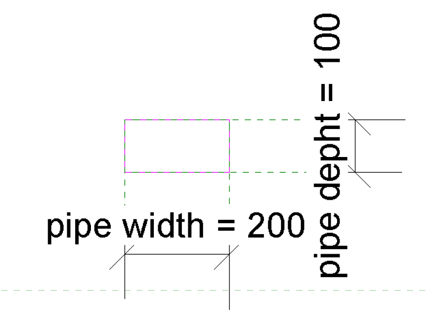
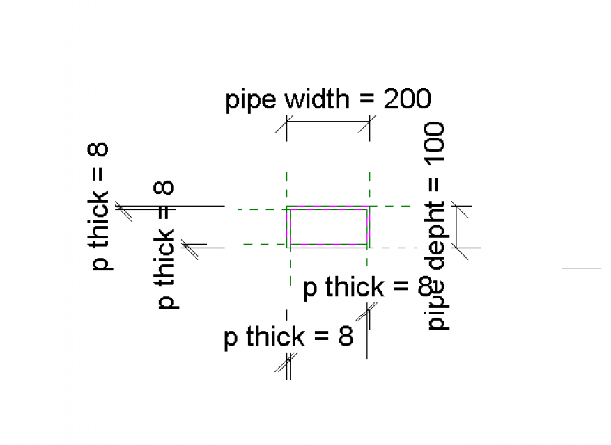
3. Create> Extrusion> Rectangle> create a reference plane (command: RP) one for each side> Allign (command: AL) each side to its reference plane> Annotate> aligned dimension
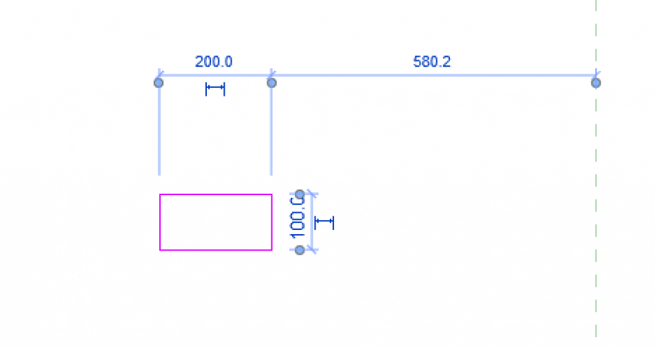
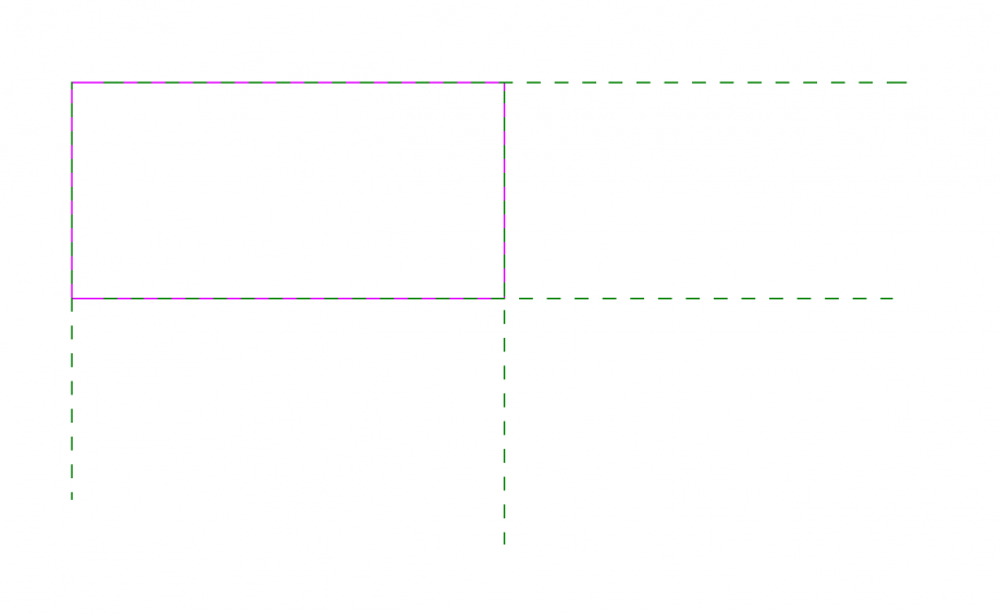
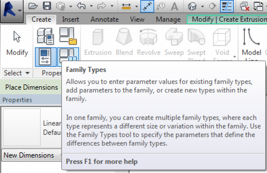
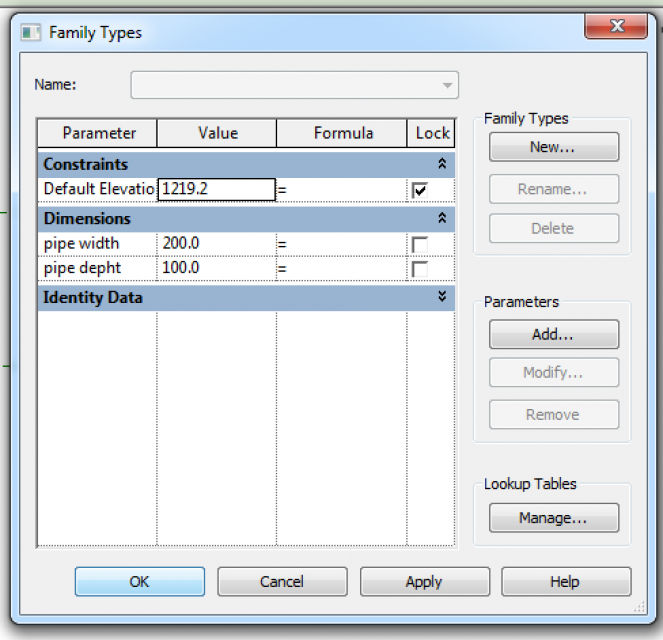
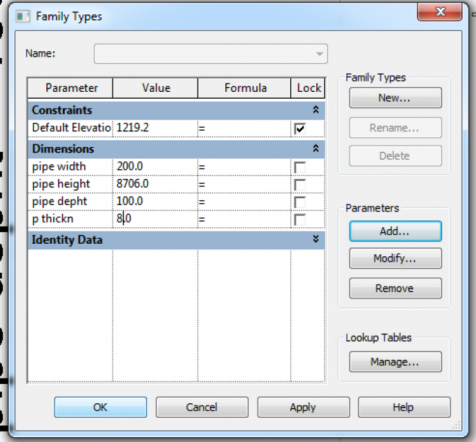
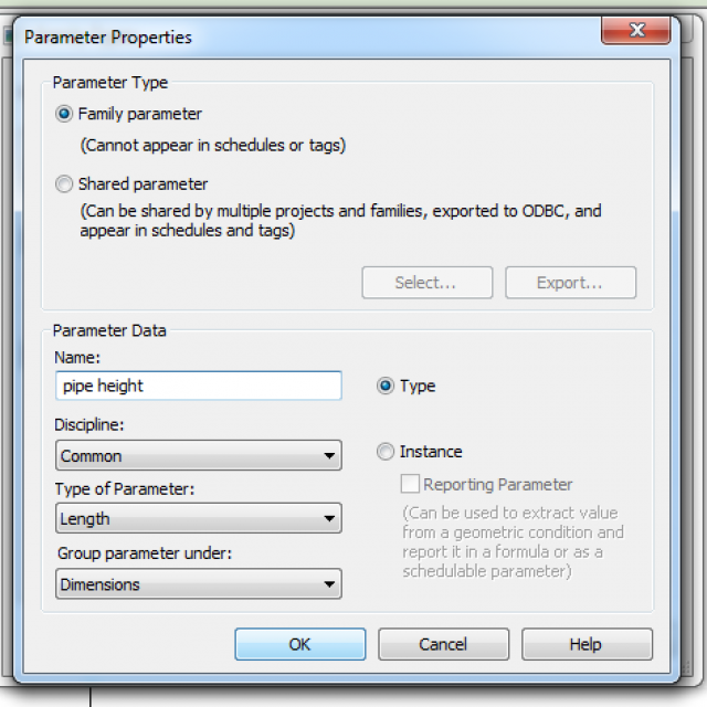
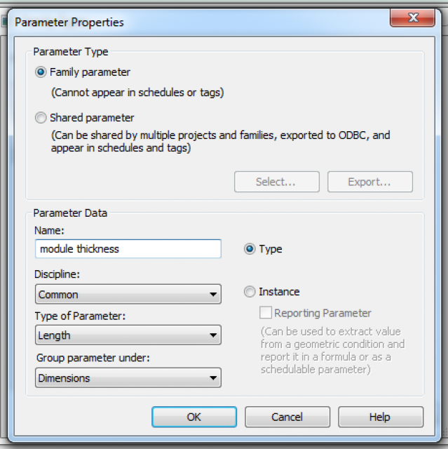
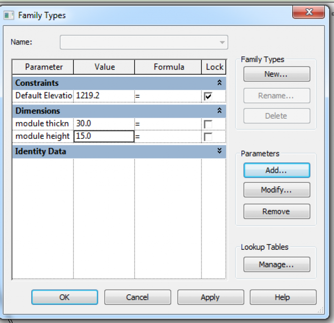
4. Create the first two parameters. Create> properties> family type> in the frame click on parameter> add.
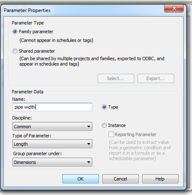
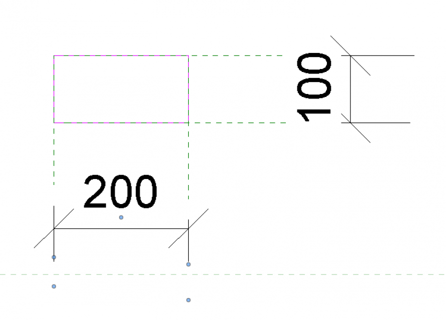
I added two TYPE parameters for the two sides of the rectangle. I choose to create only Type parameter for this facade because I needed to control the same factor in all the elements of the facade at the same time.
So, add the parameters, assign it a value, click ok and the assign the parameters to each dimension.
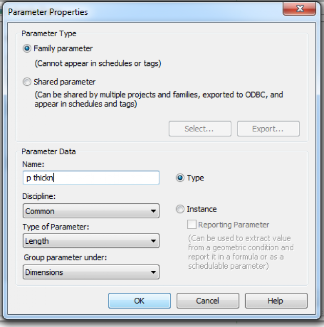
Then, I create the inner hole assigning to it another parameter because it could be helpful, in future, to control pipe thickness.
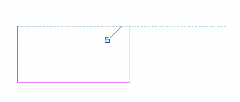
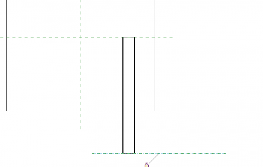
5. Offset> create reference plane for each side of the inner hole> align all the sides to their own ref plane.
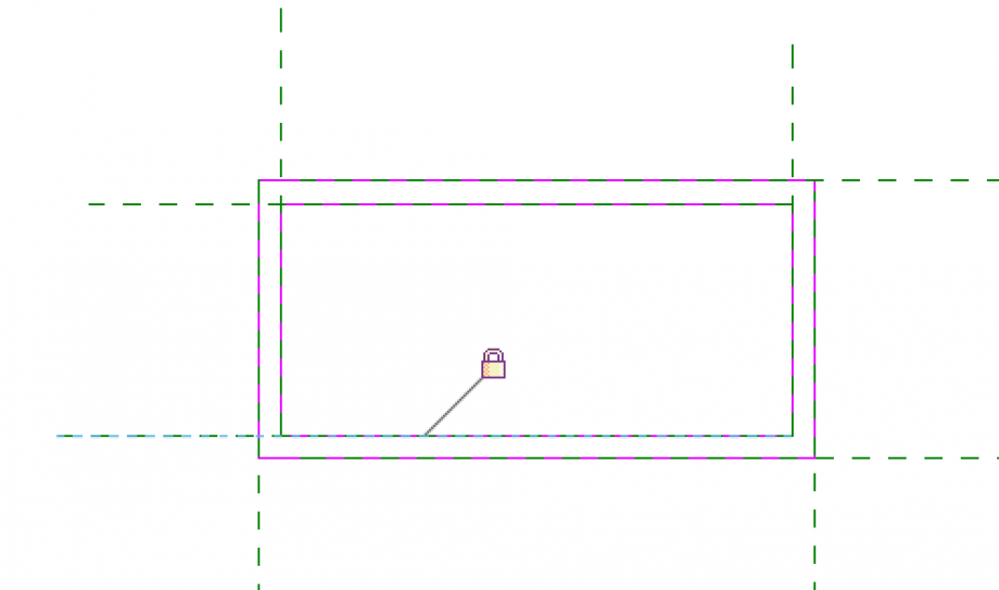
Create another parameter and assign it as is shown below.
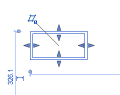
Now the extrusion is ended, click on green tick.
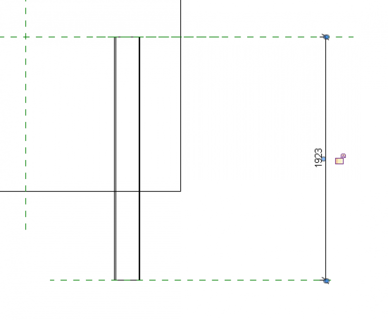
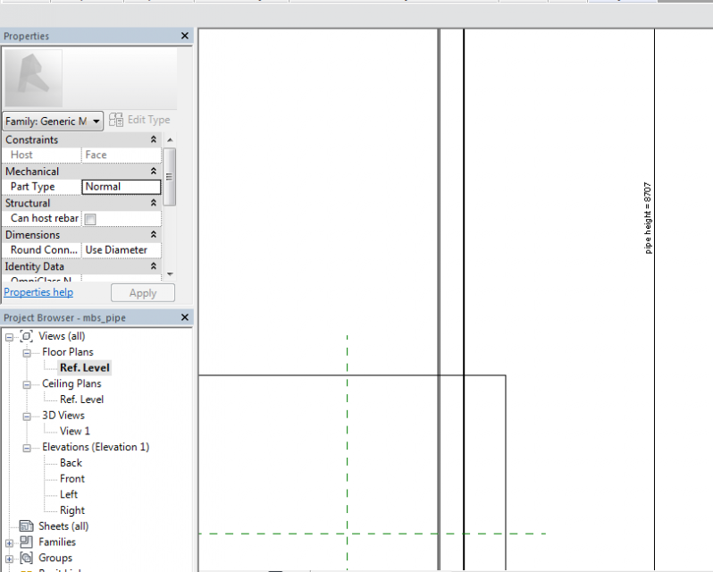
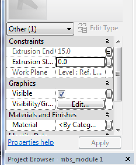
6. Create two ref planes and align them to the beginning and to the end of the extrusion> assign an aligned dimension> create a parameter for pipe height (that is 8707 mm) and assign it to the dimension previously created.
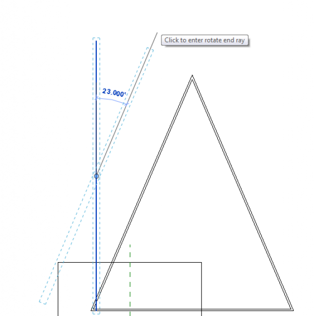
7. rotate 23° the element and all its planes.
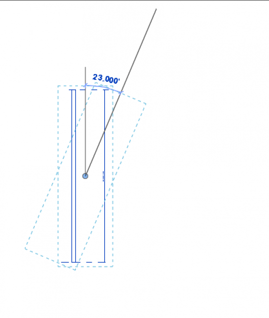
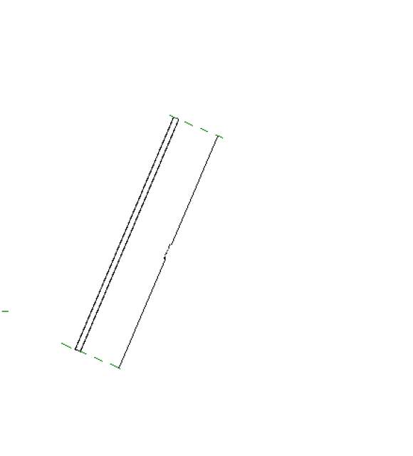
Now we have the base module of the reticular structure. We can load it into the MAIN FAMILY.
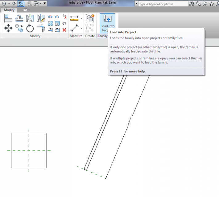
RETICULAR STRUCTURE
In this occasion only we can place it on work plane.
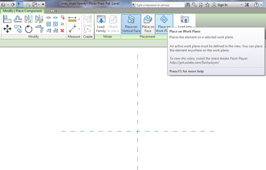
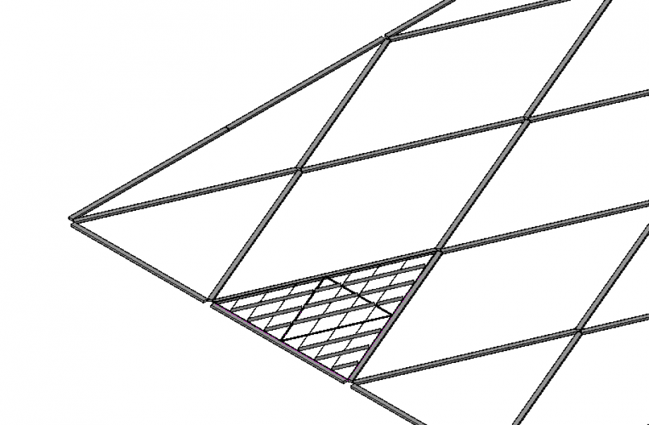
These are all the elements needed to assemble the structure.
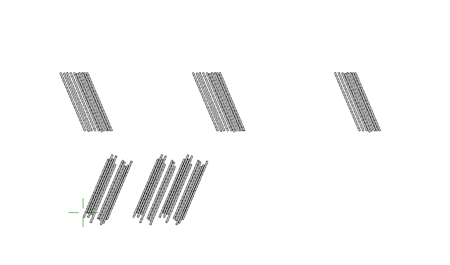
8. Use copy, move and mirror commands to compound the reticular structure.
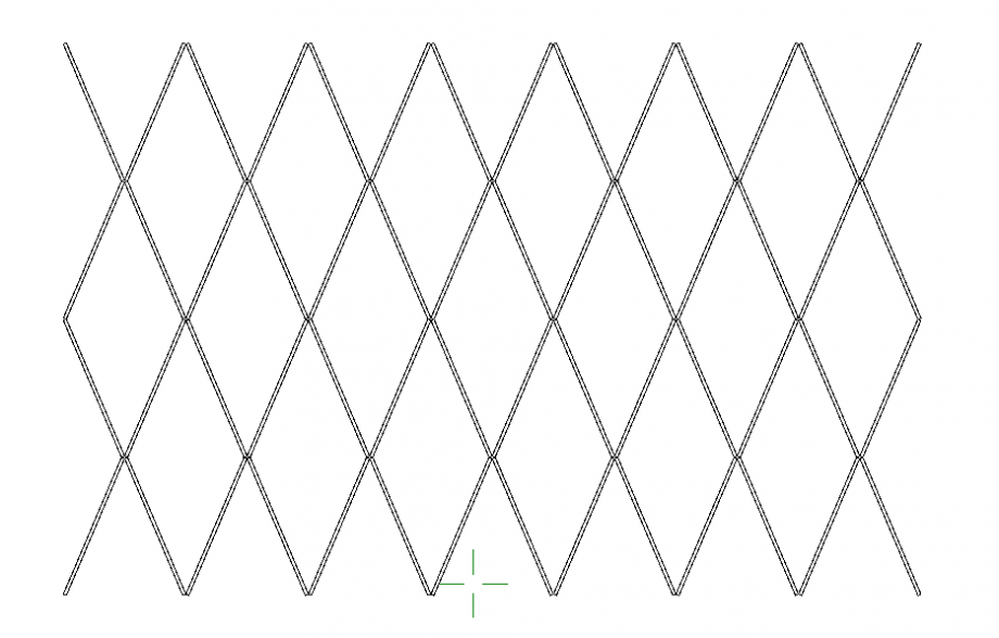
9. Since i wasn’t able to align each other the elements converging on the same node in order to move them together, i create a group.
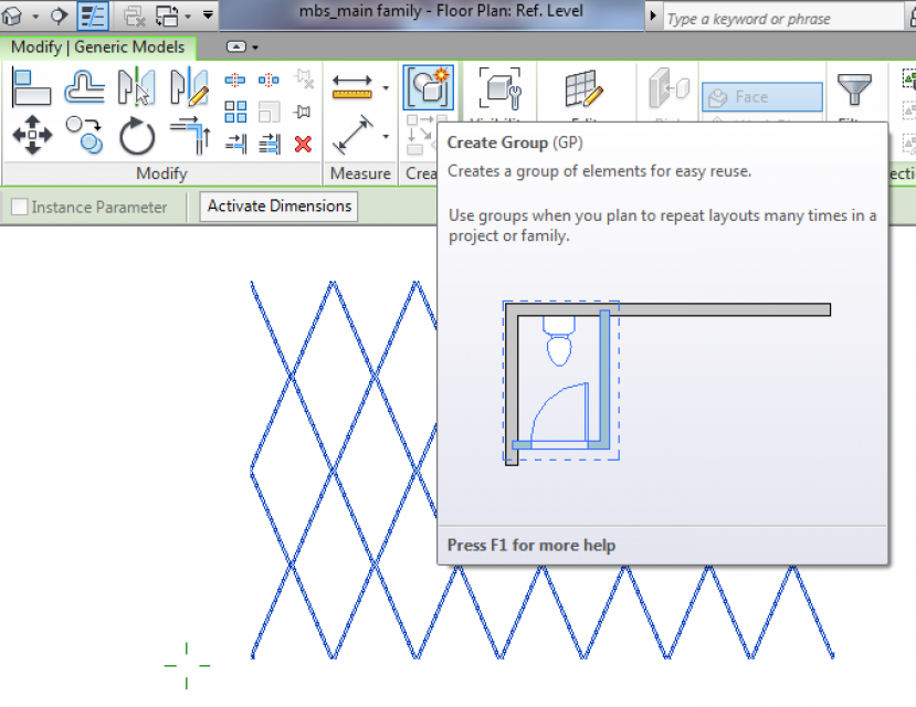
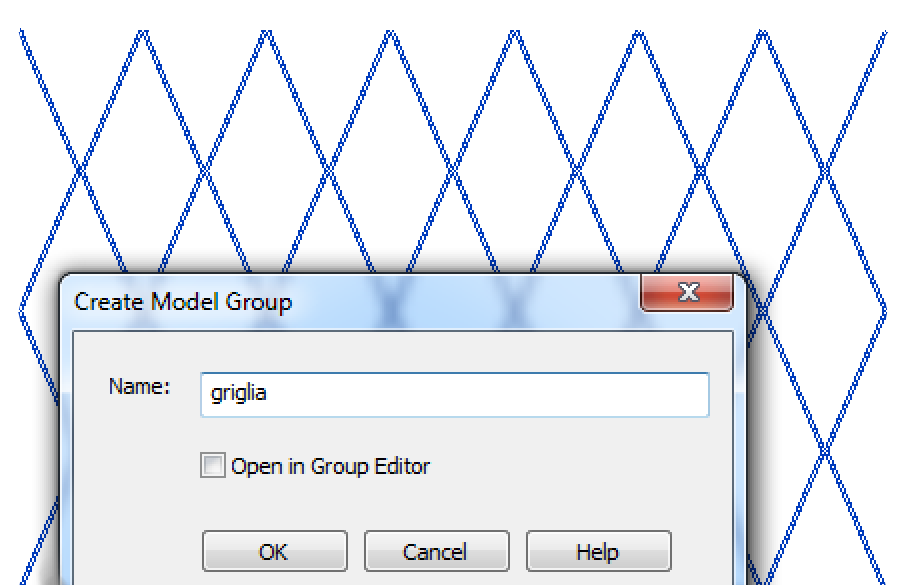
BASE MODULE FOR THE FACADE
To assemble the facade, I need some different modules to create a variation. In my case, I choose to use only three modules, but in order to have a better and more accurate result, I could use more than three modules.
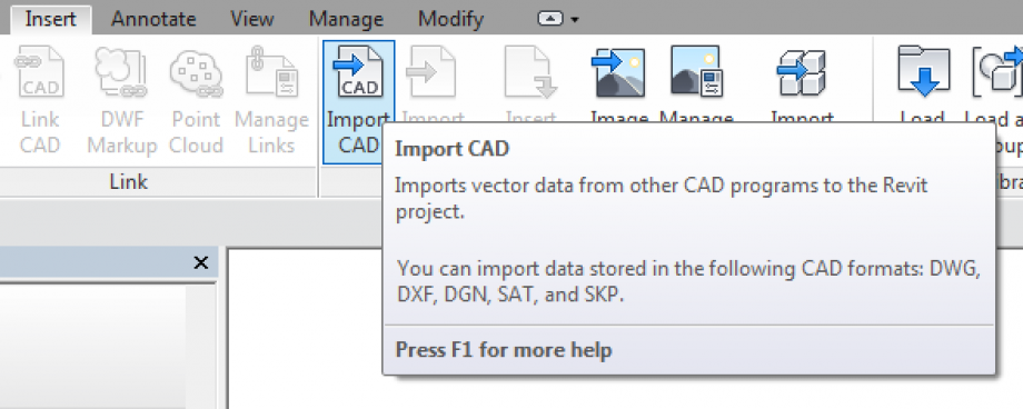
10. New file> Family> Generic model face based> rename the file: mbs_module1.
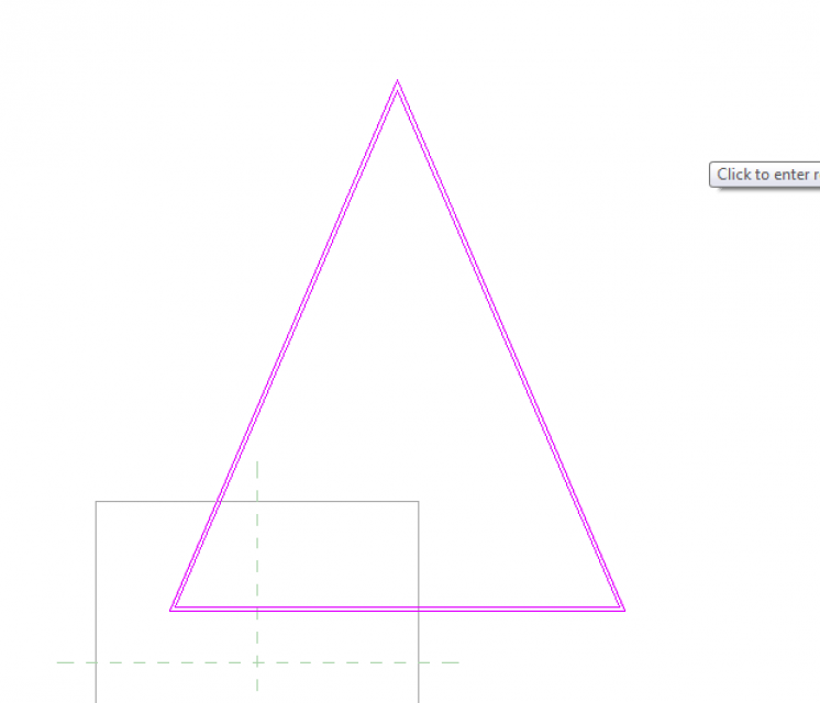
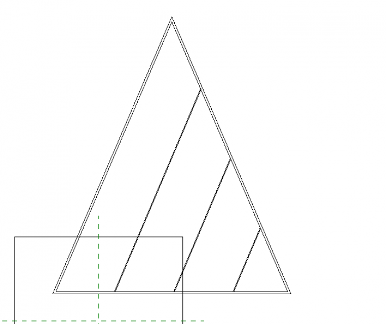
11. Then I imported a Cad file of the base triangle that I considered the base module.
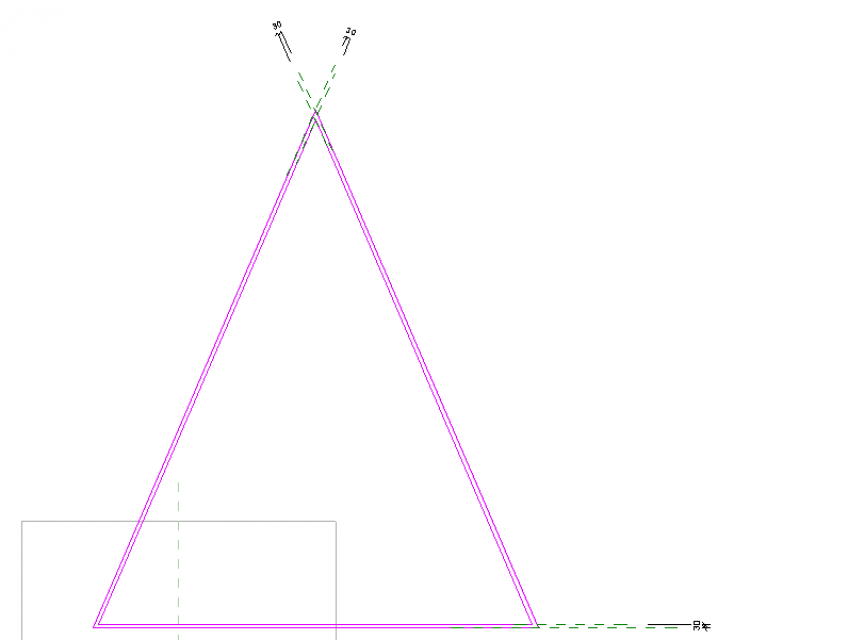
12. As it is done before, create the basic frame which holds the bris soleil. Create an extrusion and a inner hole, assign a parameter to the frame thickness as it could change in future. Create a parameter for frame height and assign it to the end of the extrusion.
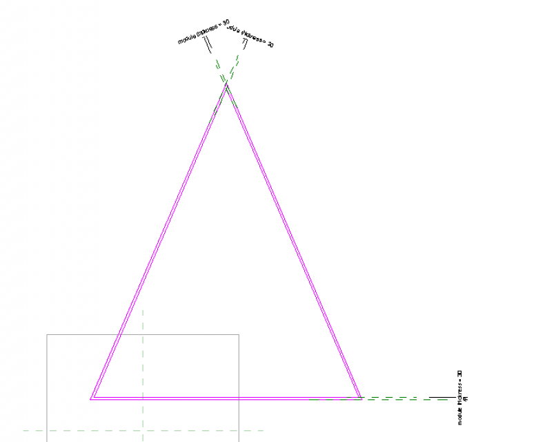
13. create a parallelepiped through extrusion command. Rotate it 23°. This will be a slice for the bris soleil.
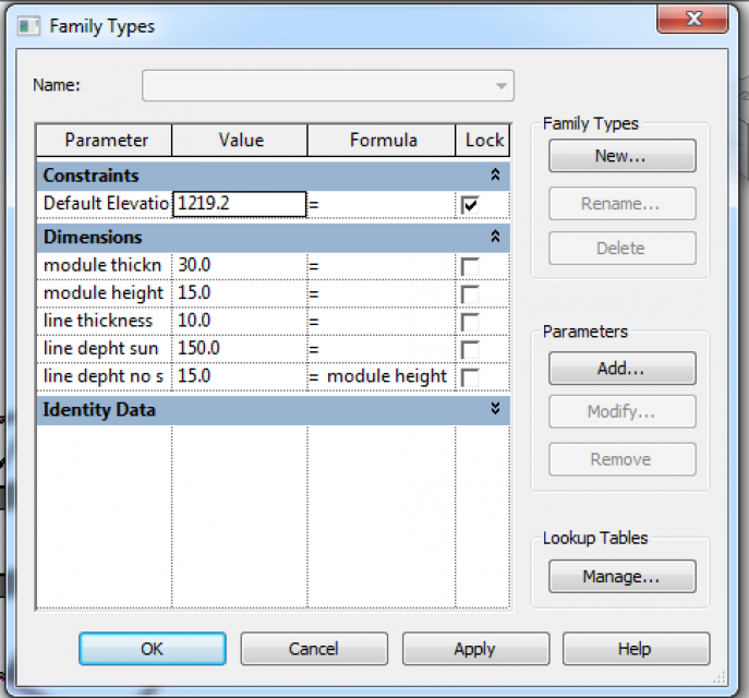
14. Create a parameter for the thickness and assign it. CREATE A PARAMETER FOR THE SLICE DEPHT. This value will varies depending on the solar radiation and the position of the module in the facade.
15. Copy the slice in order to divide the base of the triangle in four parts. Modify manually the end extrusion of the slice and fitting it to the triangle frame (I wasn’t able to align the slice any side of frame extrusion.) The slices lie on the same plane of the triangle frame: the work plane. It is not so in reality but I wasn’t able again to move vertically on work plane any object.
16. use mirror command as it is shown below
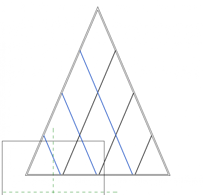
17. Create two parameter: one is for the slices that doesn’t have to screen sun rays, and another one that has to screen them. Assign it to the end of the extrusion of each slice, depending on how it is inclined. The result should be this one. (This facade as it said before receive the south-west sun)
18. We need an “up” version and a “down” version because the higher slices had to be always inclined in the same way, so we can’t use mirror command.
19. load the module 1(up and down version) into the main family and start to assemble them
20. create the other two modules following this workflow
These are their parameter
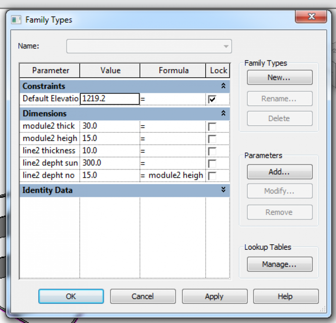

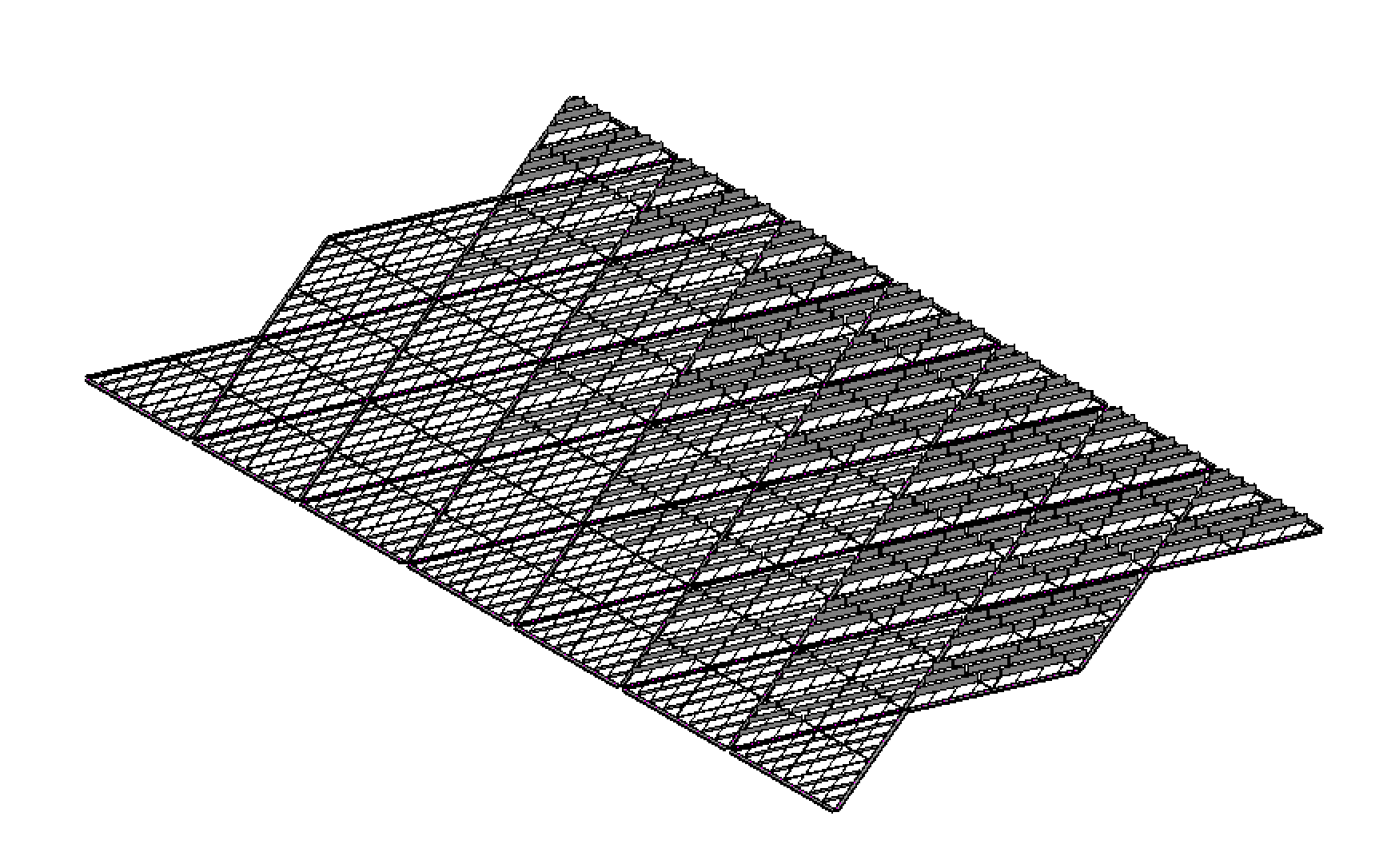
Compound them on the facade
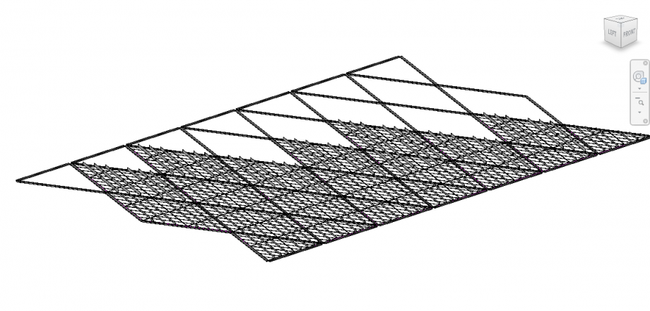
The final result should be this one.

Commenti
Manuel Andrè Bo...
Mer, 19/11/2014 - 21:02
Collegamento permanente
assebly system
hi Mabel,
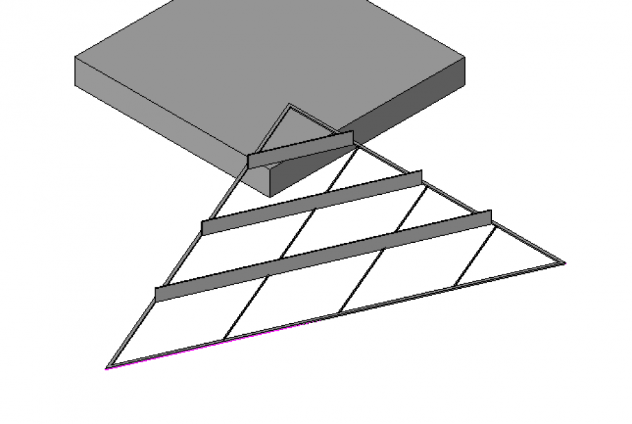
your facade based on shading performances is very interesting, but here we can't see the Tectonic strategy of the whole assembly. You correctly divided the model by structural hierarchies, but actually they seem to float each other:
Mabel Sorrentino
Gio, 20/11/2014 - 16:40
Collegamento permanente
Hi!
Hi!
As I said in the post I was unable to connect the single elements of the main structure toghether. When I tried to align their faces with align command, it failed, and I really don't know why. So, I thought it was because the elements were not parallels or perpendicular but they were diagonal each other, so Revit couldn't connect them. I tried to create a sort of node, shaping a simple parallelepiped which would have to join the elements convergent in the same node and it failed again.
The panel frame could seem a little bit thin, but as I assigned it a parameter I might modify it in future. The project is now in a processing phase. So I don't have studied its efective resistence yet.
I don't actually know even how I coud rotate the facade in vertical position. Onestly, I don't understand how I can work with a face based file in order to mount every base triangle of the main structure one on each other. I need to look for how I can mount the structure on different floors.
Anyway, thanks for the suggestions.