TRIANGULAR VARIABLE MODULES…..REVISITED!
In this third delivery I continued to develop the facade previously analysed following advices given in the last post. I added nodes to the main steel structure in order to simulate the constructive process in a better way. Furthermore, I put the triangular modules in with the shading system which fits with the solar radiation on the facade. As I already said in the previous post, this facade was carried out for the laboratorio 2M project. The main will was to adapt the shading system to the solar radiation registered on the facade. The laboratorio 3M project facade, even though with some variation, is set up on the same concept. So, it is important for us being able to control the shading system depending on solar radiation, and the schedule tool could be much useful.
So I start to show my workflow.
NODES
I started creating the first type of node that connect the horizontal pipes at the bottom with the diagonal pipes.
New> family> metric generic model faced based
create command(up above in the tools bar)> extrusion> I drew a pentagon of which the two sides above are inclined 23 degrees as it is showed in the figure.

Family types (up above in the properties menu)> add a parameter> I created a family type parameter for the node thickness


Create a reference plane (command: “RP”)> align the extrusion to it (command: “AL”)
Annotate (in the tools bar)> aligned (in the dimension menu)> I assigned a measure to the node thickness and then I assigned it the parameter previously created. (100mm is pipe thickness)

With the same workflow I created the second node type, that connect the diagonal pipes.

PIPES
Now I need to have the two kind of pipes, the horizontal one that is about 6mt long and the diagonal one that is about 8.7mt long and is inclined 23 degrees.

I created the parameters I needed, then
Create> extrusion> draw a rectangle and offset it> create reference planes as it is showed in figure> align them to the rectangle> assign the dimensions> assign the parameters to these dimensions

Now assign the pipe height parameter to the extrusion end for the horizontal pipe and for the diagonal pipe.


I wanted the pipes were metallic, so i assigned them the material parameter.
Go to the properties menu to the left side and click the grey square under “materials and finishes” line> click Add parameter> I created a family type parameter> Now go in family types menu> click on the value corresponding to the material parameter just created> assign a material (in this case I chose a solid grey pattern)


Now I have all the elements necessary to compose the main structure of the facade
MAIN STEEL STRUCTURE
New> metric generic model> rename the file file as “main family” (the place where all the elements will be connected together) and start to “load into project” nodes and pipes.
I placed first the nodes on the work plane and then all the other elements were placed on the face of the element they were connected to, in order to simulate the assembly process.


TRIANGULAR MODULES SHADING SYSTEM
Then I shaped the triangular module with the shading system. This triangular module has two different types of blades. Those inclined to the right were the ones which have to shield the sun, the other not. So they have different depth.
I created a new face based file.
Then I shaped a new extrusion as it is showed in figure and I assigned the parameter for the thickness and for the height of the triangular structure.


I created the blade of the bris soliel and I assigned them a SHARED PARAMETER.
Family type menu> add parameter> shared parameter> select> create> give the name to the shared parameter file and then to the shared parameter group> click on “new” to add a new shared parameter. (use “c_” before the name, to distinguish it from the family parameters)


I was interested to control the depth of the blades that shield the sun, so my shared parameter allow me to do this.
I created several types of the same module, those one showed in figure. Each one have different depth for the blades which have to shield the sun.

I assigned the module a wood material. This was the result.

FACADE
I created a NEW PROJECT FILE. In this place I joint the main steel structure and the triangular modules. So:
I loaded in this file first the main steel structure and then the triangular module.
In the project browser menu were added the module types previously created in the family.

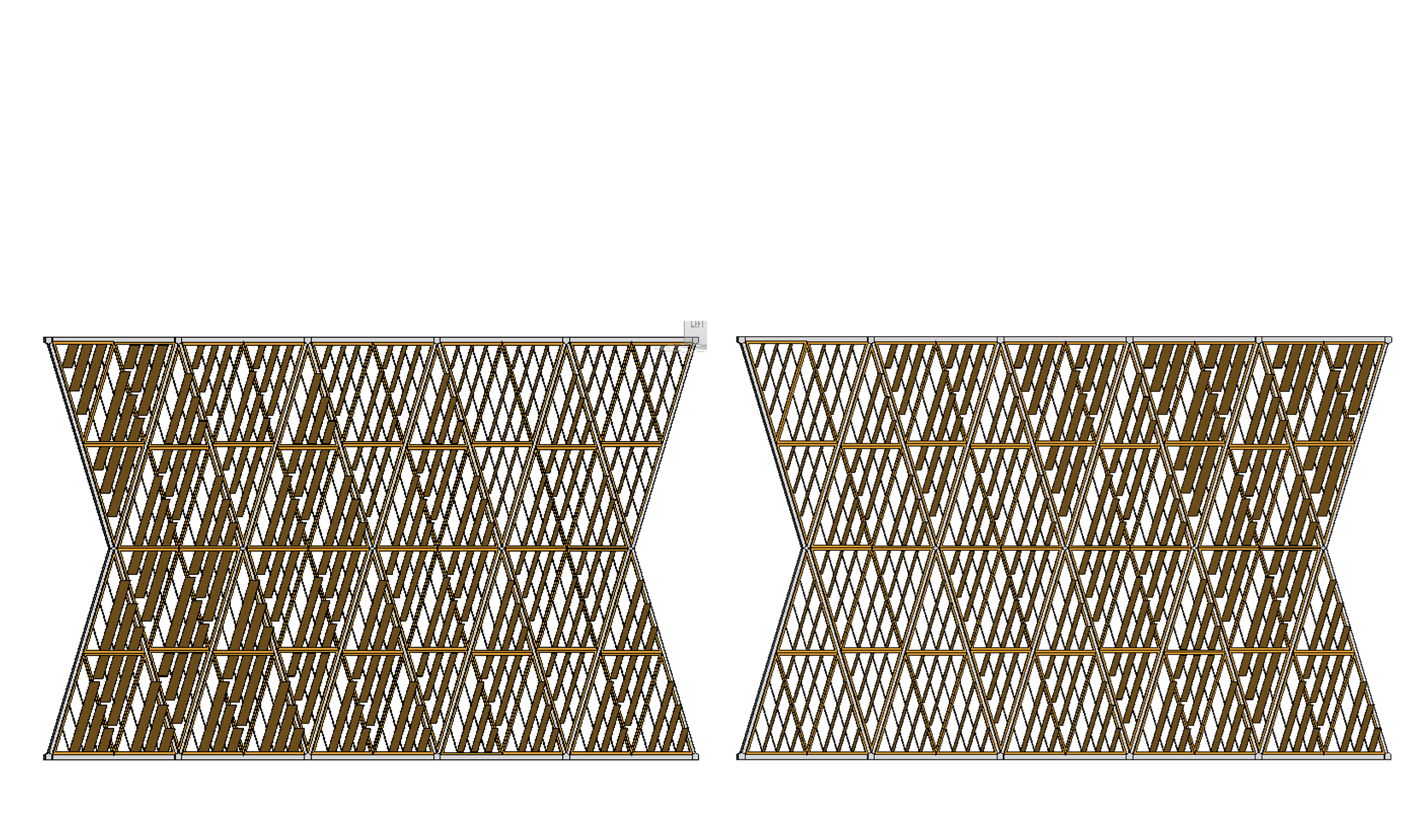
I composed the facade aligning the triangle with the steel structure.


This was the final result.


Now, going in tools bar> view> click on “schedules”> schedule/quantities> choose which category do you want to schedule> choose which parameters do you want to schedule


I tried to modify the depth of the blades and I tried to calculate the cost of the facade as it could be useful for the tasks requested in the Laboratorio 3M.


So, I have two questions:
How can I modify only one module of a type using the schedules?
How can I calculate the entire cost of the facade?
P.S. If something is not clear with the workflow, probably it is more clearly explained in the previous post.