Modular furniture
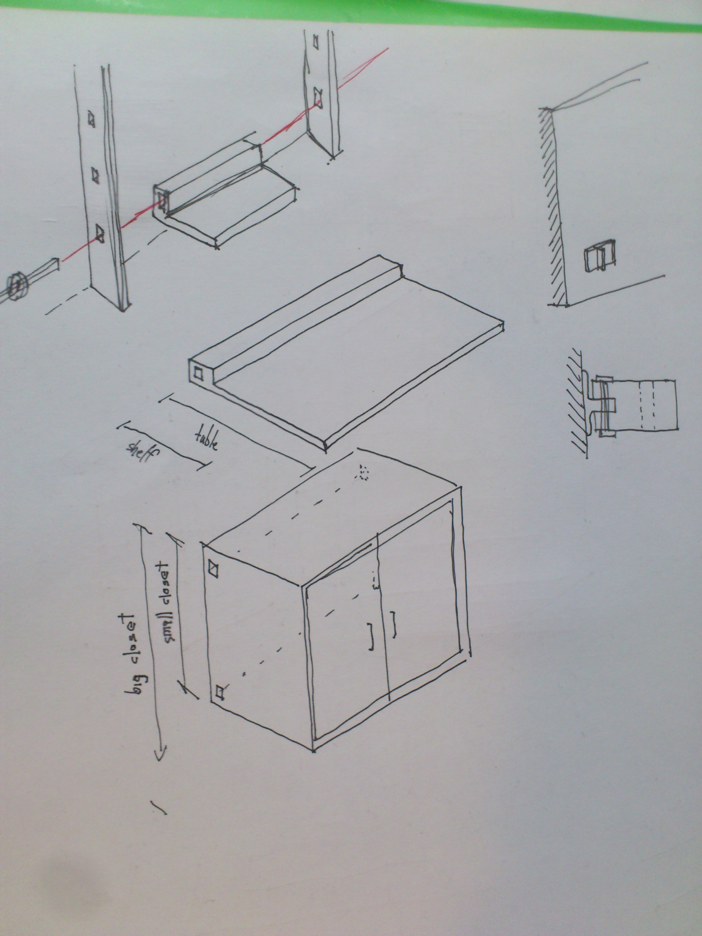
My idea of how to make the place adaptive to different life-style situations of inhabitants, who would live for a short or long period of time in my created apartments, is to create a modular furniture. So that each room (except the bathrooms) could be rearranged so that it suits the people, who use the apartments.
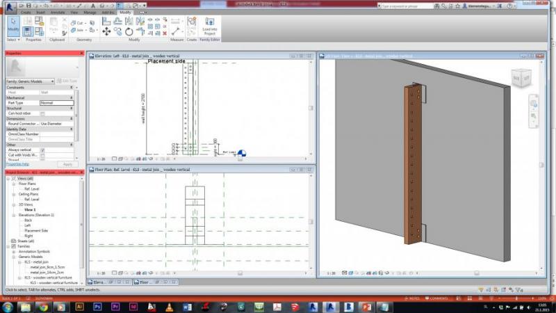
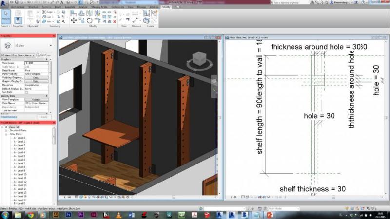
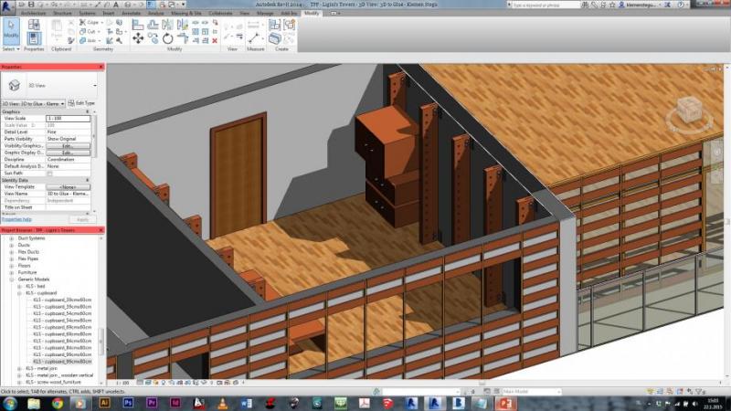
As it is seen on the head picture, the whole system is made of vertical elements into which you can attach a lot of things - shelfs, desks, cupboards, cabinets or even beds. Those vertical elements are attached to the walls by metal joins.
Here is how the creation goes:
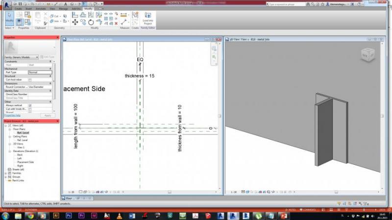
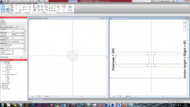
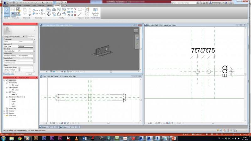
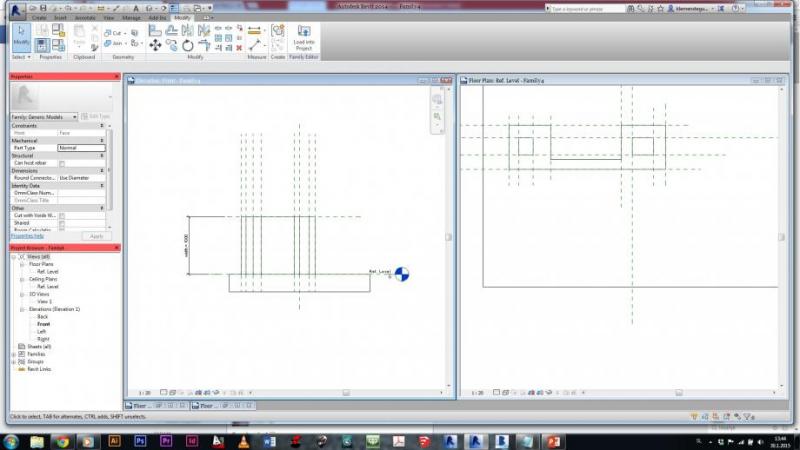
- I designed metal joins in the METRIC GENERIC WALL based family. First, i created all neccessary reference planes, than i created an extrusion in the shape of metal join, which i wanted. And i made all the parameters for the dimensions of the join and parameter for the material as well:
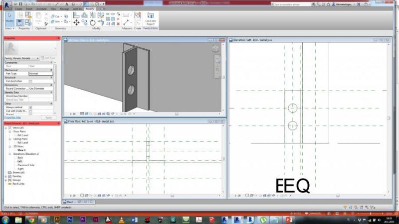
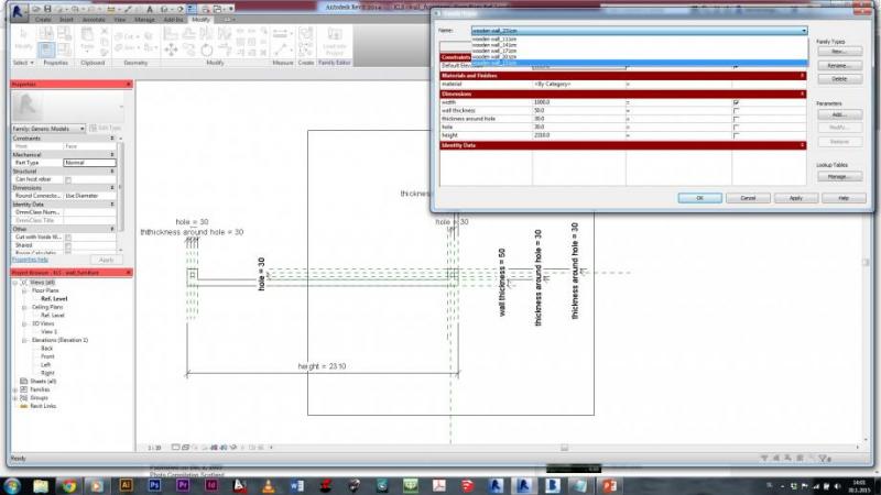
-Next i did the holes in this join, which will connect the vertical element with this join. The holes were created by using void forms, which is almost the same as making extrusion, though it creates an empty space. The holes were also set in the proper distance from one another and a parameter for the radius was set:
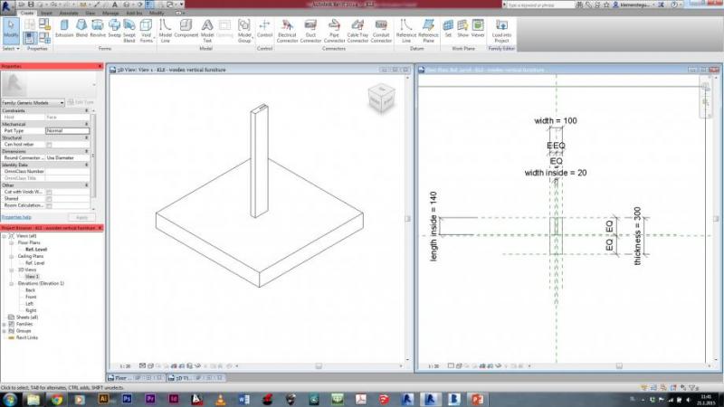
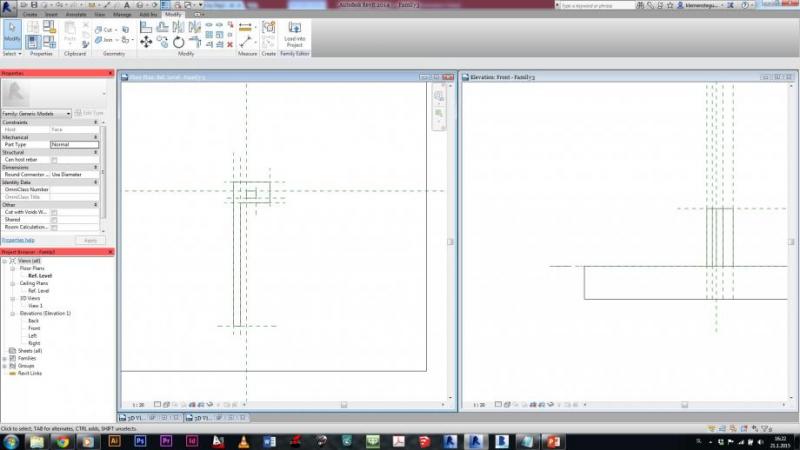
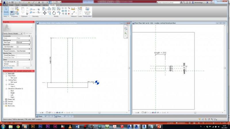
-With this join made, i moved on to create the vertical element, which would be made of wood. AS before, i created reference planes and made an extrusion, and equiped everything with parameters:
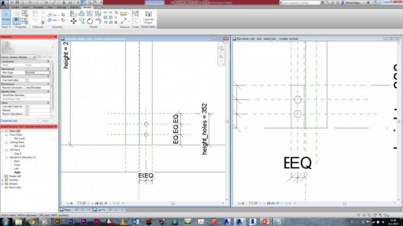
-Next step is to create the holes in this vertical element, so that it could be fixed to the metal join. To to this, i created the same reference planes, as i created them when creating holes in the metal join, and i also set the same parameters for them:
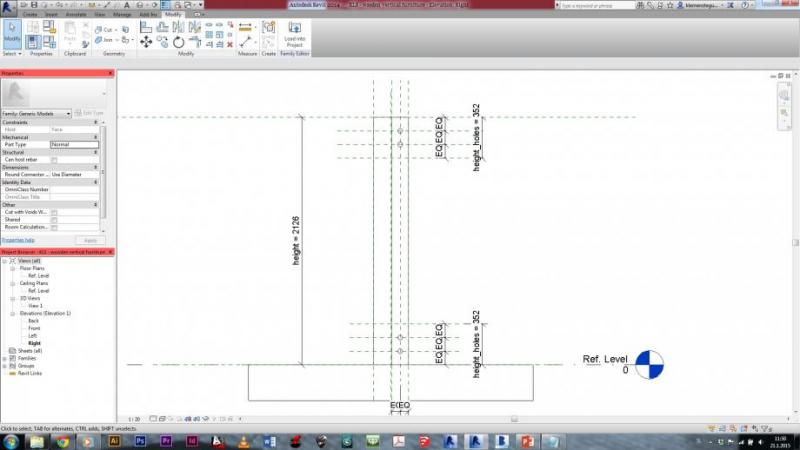
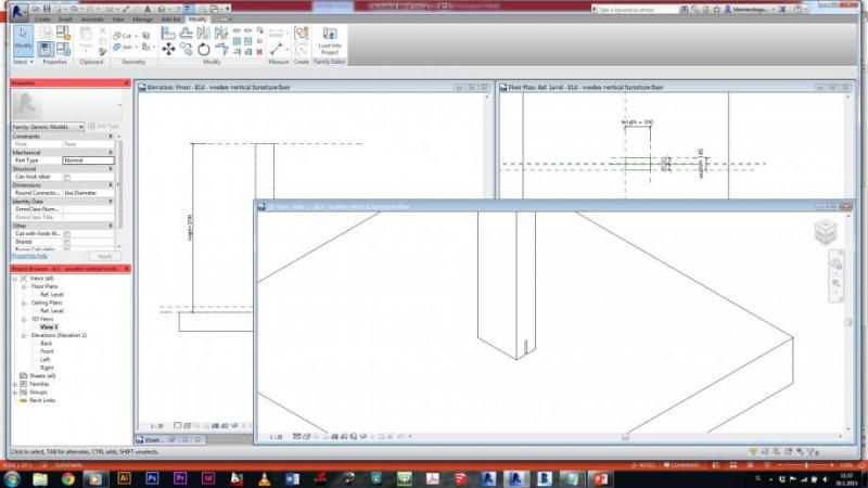
-And since this vertical element will be attached to the wall at the bottom and at the top, I also created holes at the top of it, in the same way, as i created them at the bottom:
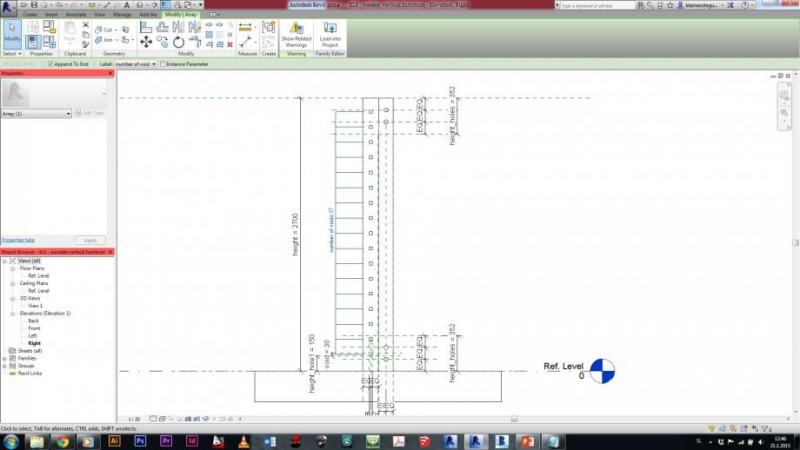
-Last part of creating the vertical part are the holes, into which we could fix different kind of furniture. They were also created by the void forms and by the array tool:
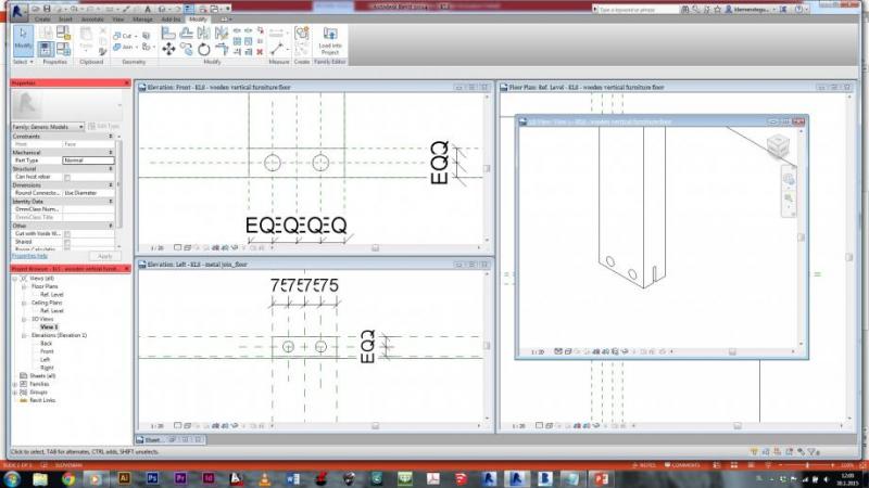
-Now i had to join those two familys, which i created. I duplicated the family of metal join, because i used it as a template for the creation of the whole element - the parameters, which were set for the metal join were also going to be used as most of the paramaeters of the vertical element. So i just changed the neccessary parameters of the vertical element with the ones of the metal join:
Now i'm going to create furniture parts.
----------------------------------------------------------------------------------------------------------------------------------------------------------------------------------
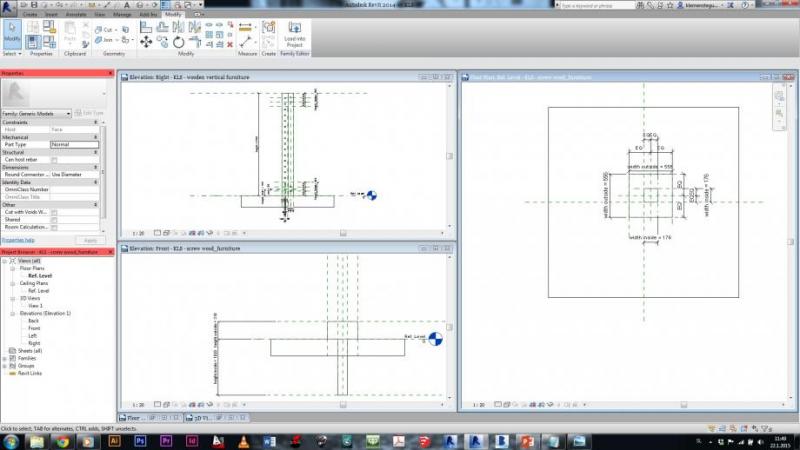
- Before creating furniture parts i created a screw, with which the wooden vertical element and metal join are joined together. It was created as METRIC GENERIC FACE BASED family. I created 3 circular extrusions and equiped them with the parameters to control its shape, when imported in the family where are wooden element and metal join:
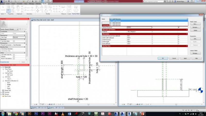
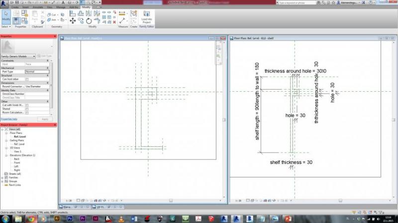
- After that i created first family for furniture parts (metric generic face based). First i set all reference planes and then i created the shape which i wanted. This first piece was going to be a shelf or a desk:
-I set the parameter to control the length, width, thickness of the shelf, and also the parameters for the hole in the ''handle'' of the element, which is neccessary for attachment to the vertical wooden element, created before. I made 4 different types for this piece of furniture:
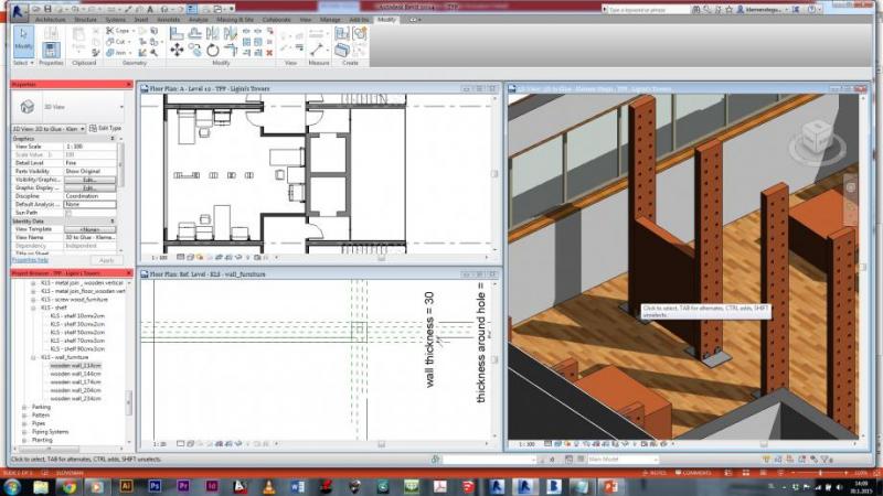
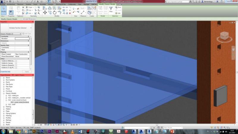
-After importing in the project this is how it could look a part of the room with these types of shelfs (or in this case, a desk):
-To attach shelf and other furniture, which i intend to create, i would also need a screw for connections between wooden verticals and furniture. So i created one. Created as furniture and screw before, in metric generic face based family. The width of the screw which connects furniture and vertical is fixed to the dimension of the holes in the vertical, and the length of it is also fixed to 50cm, so it could be used even in the corner of the room, where the first vertical is placed 60cm from the wall:
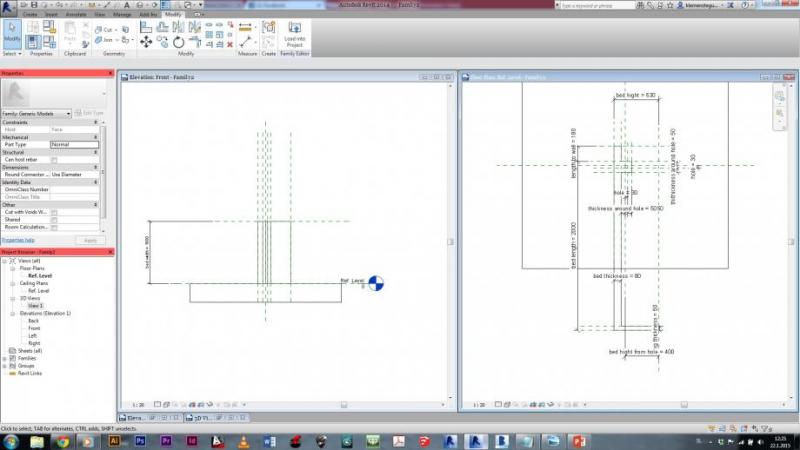
-Next piece of furniture is a simple bed. It is also done as metric generic face based model, and it is similar as the shelf, with the addition of ''legs'' for the bed on the opposite side of the vertical elements:
- The parameters are set similar as for the shelf, with the addition of the height parameter for the height of the ''leg''. Some of the parameters are set as fixed - dimension for the hole, where bed is attached to the vertical element, thickness of material around the hole and the height of the legs - this one is calculated according to the height of the hole on which the bed is attached, which is 33cm, so the actual height of the bad is 46cm:
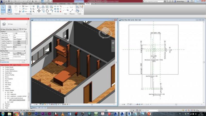
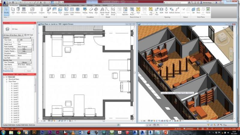
-This is how it looks in the Ligini's tower:
----------------------------------------------------------------------------------------------------------------------------------------------------------------------------------
The last piece of furniture, which i created for this modular system are cupboards.
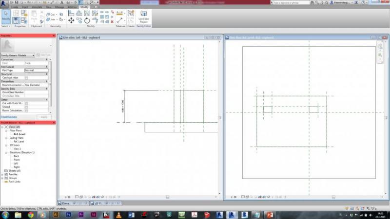
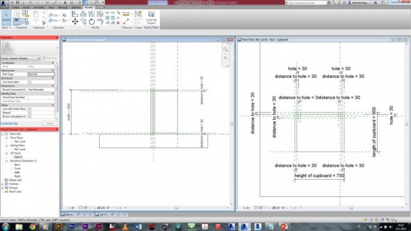
I created reference planes for the shape of the cupboard and reference planes for the holes in the cupboard. After that, i created the extrusion with the holes in it:
After that, i set the parameters for the dimensions of the cupboard. Width, hole seize and distance from edge to the holes were set as fixed parameters: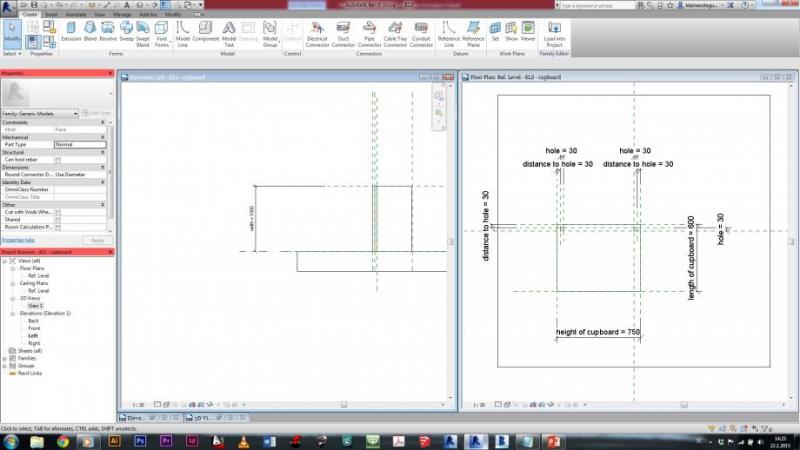
With this made, i created a void inside the extrusion to get the inside space of the cupboard. I set the neccessary parameters for this inside void as well:
Furthermore i created two more extrusions for the doors of the cupboard:
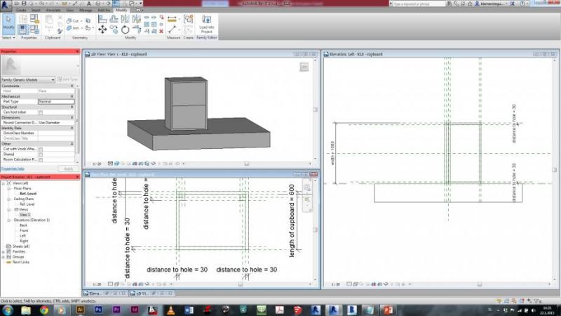
From this next printscreen you can notice that i also made some handles on the doors of the cupboards. And with all this made i created a few different type of cupboards - types are different regarding their height and deepness:

And to have a better idea how this would look in the project, here is the last picture showing it:
----------------------------------------------------------------------------------------------------------------------------------------------------------------------------------
After speaking wit profesor I decided to do another piece of furniture. This time this would be the elements, that would divide bigger rooms into smaller places according to the needs of inhabitants - so we are talking about optional walls. The design is almost the same as the one for the furniture which is placed at the wall, though it has some changes, because this time it is fixed to the floor of the apartment.
First I needed a new metal join element, which allows the vertical element to be fixed on the ground. It was made as METRIC GENERIC FLOOR BASED MODEL. First, all the reference planes were created and the extrusion. All parameters were set as foor the metal join in the wall element:
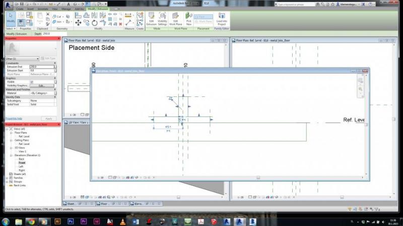
With voids I created the holes for the screws, to be able to fix the vertical element on this join:
So, the metal join was complete. Now I started creating new vertical wooden element - first all reference planes,then extrusion and setting the parameters - height, width were the same as with the vertical element, which was created for the wll furniture:
Now I created a void, to create the hole in my extrusion for the connection with metal join previously created . so the dimensions of the void are the same as the dimensions of the metal join:
For the connection with metal join are also needed the holes for the screws - again using voids to create them, with the same dimensions as the one in metal join:
With this done, I now created a void for the holes with which the furniture elements will be connected. All dimensions are of course the same, as the voids in the wall vertical element:
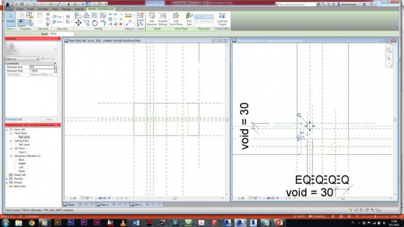
But since this element will be positioned in the middle of the room, I think that it would be practical to be able to attach the furniture on it from two sides. Thats why i created anothe void in the other side of the element:
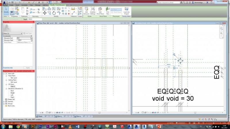
After the first two voids created, i used the arry tool to mutliply them:
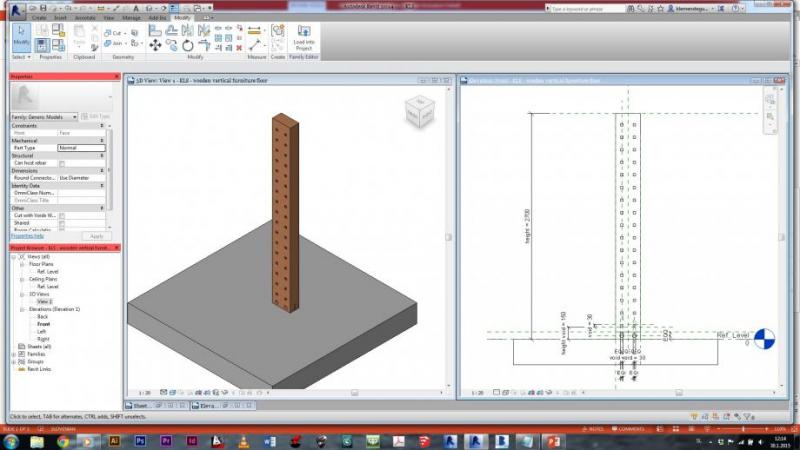
So, I had now metal join and new vertical wooden element. I created new family - METRIC GENERIC FLOOR BASED in which i imported both two elements and also a screw which was created before. So all of them were now assembled into the finished element:
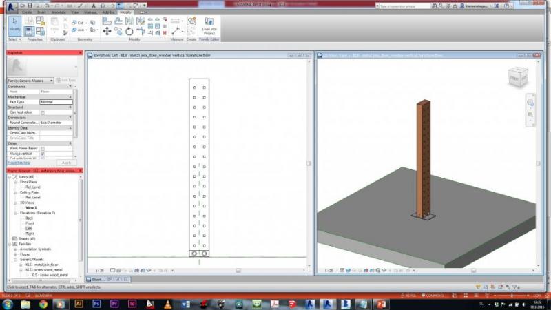
With element created, I imported it into my project:
Now, the final element would be a wooden wall, to separate parts of the room from each other. Created as all furniture elements before - it has holes which enables it to be attached to the wooden verticals:
I created some types of this element - they are different from each other by the size:
And this is how this element looks in the project: