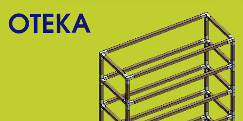
OTEKA: a joint-beam shelf unit
This is the modelling procee of OTEKA: a shelf sytem, with parametric dimensions, made of steel angular joints and wooden linear beam. This will be the mother family. Inside OTEKA family there will be two nested families: joint+beam.
NB: In this post I don't explain how to model. For basic tips about modelling you can see my previous post. Here you can find the difference between Type and Instance parameters, how to use Family Types, how to manage nested families, how to use formulas for parameters, how to organise YES/NO parameter with Visibility properties.
NM_wood milled beam.rfa
The linear components of my shelf system are wooden beams with two milled ends, inserts for the joint. Let's see the model.
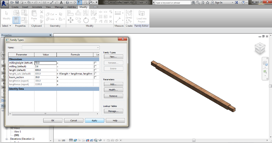
"beam_section" is a Type parameter: the section of the element is decided "before", I buy this elements with defined sections, I choose one of them, the most appropriate for my project.
"length" is a Instance parameter (default): I can cut an element (with a defined section) with different lengths. Also, this parameter allows to modify the dimension whem I load this family elsewhere.
About the milling parameters, they referes to a Void Forms and they are Instances because I can adjust them to different joints.
IMPORTANT: Type and Instance are strongly different. The first one is about standard, defined data. Restricted informations. The second one is a variable condition. It's up to you decide how to go through this issue. Often, it's easy to figure out with this thinking about components' production/construction or their use in the project. You can find the element in defined conditions? Or you can customize it? You can adapt your component according to the situation? Or it has to adapt to other ones?
If you have to buy this component you have to consider the supplier has this wooden elements with a maximum length. So I modelled this component using a formula for the length parameter. "lenght_calc" is the instance parameter assigned to the global dimension of the element. The value is ruled by a conditional formula IF. "lengthmax" and "lengthmin" are the two reporting paramters I set up to be the limitation for "length", the "typing" parameter. The IF formula has a scheme =IF(<condition>, <true>, <false>). According to my model, if "length" value is smaller than "lengthmax", "lenght_calc" will take the same. If not, "lenght_calc" will take the "lengthmax" value.
So, the formula is =IF(length>lengthmax, lengthmax, length)
By this way the length of the element never exceed of maximum value I set up (and OTEKA's maximum dimensions will do the same).
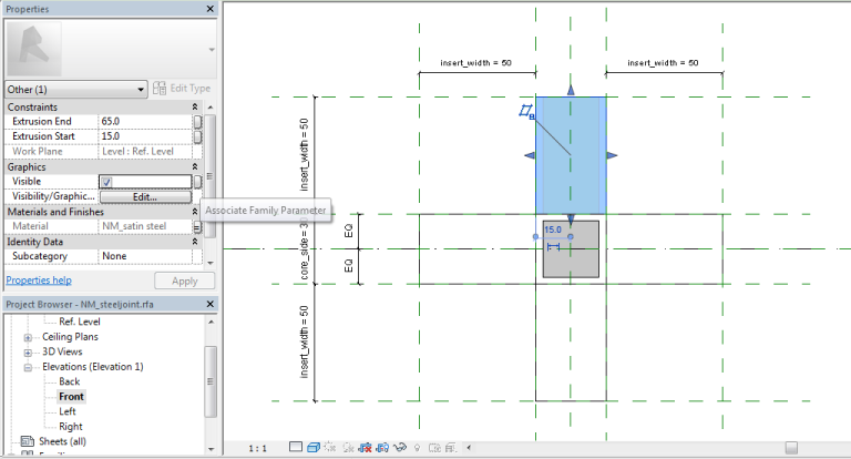
NM_steeljoint.rfa
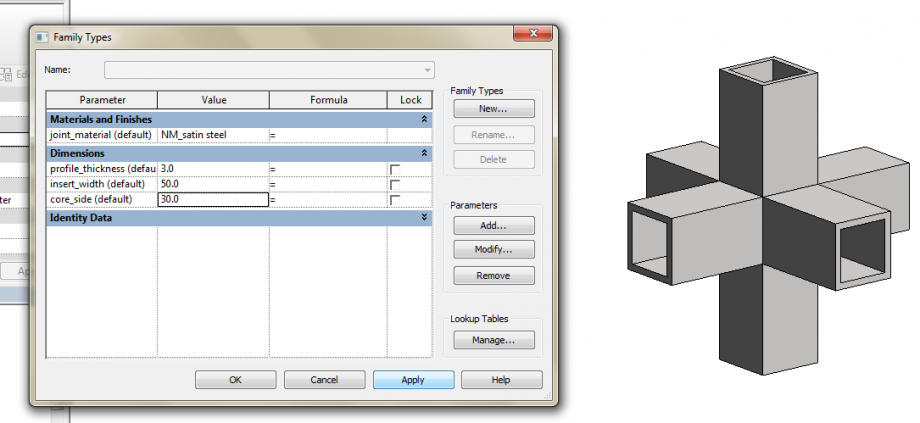
The dimensions are Instances because I can adjust the joint to different elements.
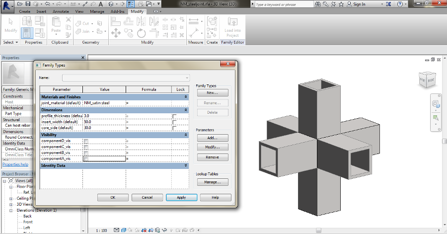
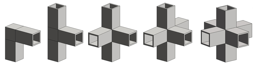
The steel joint is designed as a modular spatial connection with different configurations (the family types).
Using Family Type means to give different values to every Type Parameter depending on the different configuration and "save" them.
I decided to use a YES/NO parameter assigned to the Visibility property of the elements. First, add the type parameter in the family. Then, assign this parameter to "Visible" in the Properties panel of the selected element.
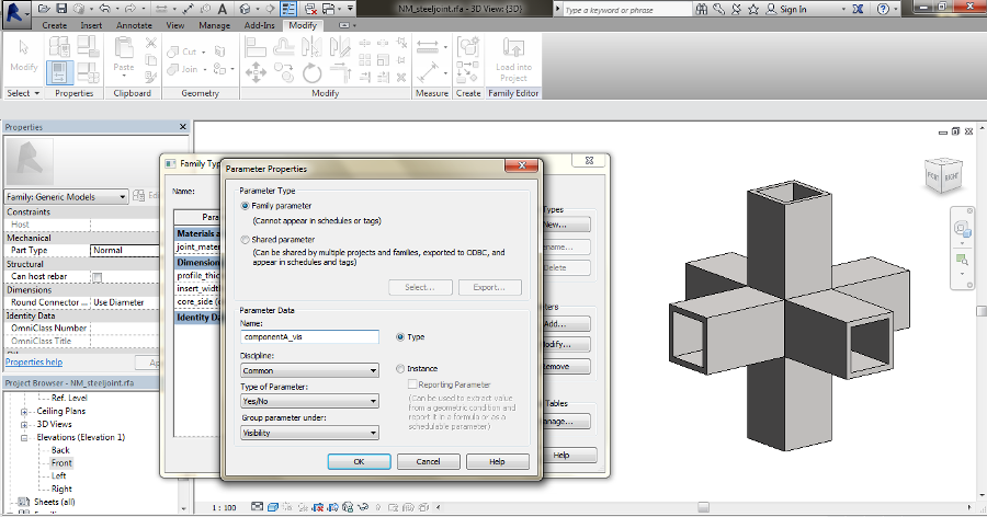
Using different type YES/NO parameters and assigning them to the different elements visibility properties I provide the different Joint Types. Respectively O, T, E, K, A joints.
The flagged parameter means YES, so visible. Unflagged means NO, so non-visible. For example, the K joint has one non-visible element (so the corresponding parameter is unflagged). The E joint has two non-visible elements (so the corresponding two parameters are unflagged).
Notice: when you this property in Family Template, you see every "non-visible" element with light grey edges, but when you Load the family elsewhere you will see only visible elements.
 Done! Now it's time nesting time. Now place the two components in the mother family and model the global system.
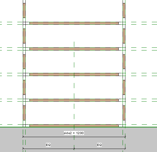
NM_Oteka.rfa
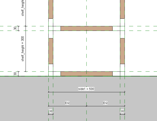
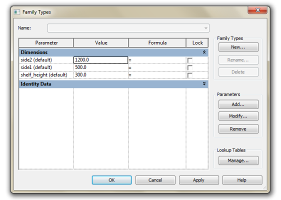
In this case I used two different joints (E, K). To choose the joints, I can select the Family Types by clicking them in the Properties panel. And I can modify them whenever I want. The elements (the joints and the beams) are aligned with different Reference Plans.
The dimension Instance parameters (assigned to the plans' distances) rule the two sides of the shelf system and the distance of the different levels.
Sp, that's it. Now I have my brand new parametric shelf system. And you too! Check out the attachments below.