


 Justine Musielinski
Ven, 08/11/2024 - 09:11
Justine Musielinski
Ven, 08/11/2024 - 09:11
1. Create family -> English -> generic metric model
2. Family type -> new parameter -> shared parameters -> select -> shared parameters file -> parameter group = "lezione 3"
 3. Family type -> click on H/L/l -> modify -> occurrence -> validate
 4. Create 2 reference planes -> annotate -> align
5. Create -> extrusion -> square -> align
6. In front view -> create reference line -> annotate -> align
7. Align
8. Define my labels (H, L, l) (Go to display options -> shaded)
9. Create -> construction project
10. Insert -> load family -> "TPP - component"
11. Tree -> family -> generic model -> place family type in project (Go to view -> camera)
12. View -> schedule + quantity -> generic model -> add "S_length" and type "S_width" "S_height" -> validate
 13. View -> close inactive windows -> tile view
14. Family type -> new parameter -> select shared parameter + "type" -> select -> modify -> new parameter -> "text" -> name it "S_name" -> validate
 15. Load into the project
16. Schedule + quantity -> generic model and type -> add S_name, S_length, S_width, S_height
17. Family type -> modify S_name -> occurrence -> load into project
18. Create -> reference plane (split solids into 2 parts)

19. Select the 2 different parts -> name north and south
20. Create a reference plane -> rename left as north and right as south
21. Click on schedule -> sort and group -> modify -> sort by "S_name" -> select "blank line" -> uncheck "itemize every instance" -> field -> modify -> add "comment"


22. View -> visibility graphics -> filter -> add -> modify/new -> new parameter -> name -> check generic model -> filter setting -> comment -> equals -> "yellow," "red," "pink" -> pattern -> choose color + "solid fill"


 AmelieMoy
Ven, 08/11/2024 - 09:18
AmelieMoy
Ven, 08/11/2024 - 09:18
- Starting from the family created previously, the family in which we have activated the occurrence, to be able to modify the measures at our will.
- A new parameter will be added to this family: the text
- We import the family into a new project
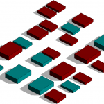
- Place the shapes on a plan
- After placing the elements in the plan, we place reference lines in order to delimit zones to separate the different elements
- Once delimited, we select the elements of the zone and in the properties we assign a name to the zone in the parameter S_Name of the family
example: north, south, east, west
- In nomenclature, we select the fields S_Name, S_Height, S_Length, S_Width + Comment
Then sort by comment and check blank line.
- In View --> Filter --> new filter
- Create as many new filters as sections made with the reference lines.
- We select Generic model
- In filter rule: generic model is associated with the comment and Eglal --> the name of the filter that we want to associate with the zone.
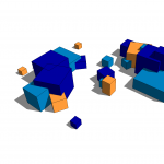
- Then in the icon just above Filter, in Visibility/Graphics, we choose filter, the filters already created according to the zones are present, we will be able to associate colors with the name of each filter. To associate a color: pattern --> solid fill & color.
- In plan, in the property bar, the comment option we choose the color chosen for the filters.