


 Azra Gokhan
Mar, 19/11/2024 - 21:11
Azra Gokhan
Mar, 19/11/2024 - 21:11
1. first i create family, then open generic metric model
2.i acces family type new parameter then shared parameters and select shared parameters file then parameter group, lesson 3
3. i adjust the family types and then click on H/L/l and modify and change them to instance
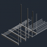
4. i created 2 reference planes then selected annotate and align
5. i created a square with extrusion and then aligned
6. i look to front view and then created a reference line annotated and aligned
7.i defined my labels.i go to display options and select shaded
8. i create a new construction project
9. i inserted the family than "TPP , component
10. from family go to generic model and placed family type in my project
11. i created a schedule then generic model and added "S_length" and type "S_width" "S_height" and validated them.
12. go to family type and select new parameter then select shared parameter add "type" then select and modify , new parameter select "text" and name it "S_name" and validate.
13. i loaded into the project.
14. i created new schedule added quantity go to generic model and type add S_name, S_length, S_width, S_height
15. i go to family types and modify S_name and loaded into project.
16. i then create 2 diffrent reference plane.
17. and then select upper and lower parts named it north and south.
18. i create a reference plane and rename left as southwest and right as southeast.
19. then i clicked on schedule, sort and group and modify, sort by "S_name" and select "blank line" and uncheck "itemize every instance", field and then modify and add comment.
20. i go to view to visibility graphics and filter added new modify then new parameter, name and check generic model i go to filter settings, comment , equals select "gray''''dark gray''''light gray'' and solid fill.
Mar, 19/11/2024 - 21:14
 Azra Gokhan
Mar, 19/11/2024 - 21:04
Azra Gokhan
Mar, 19/11/2024 - 21:04
Creo due 'piani di riferimento'. 2. Disegno la mia forma con 'linee di modello'. Allungo i piani di riferimento alle dimensioni desiderate e colloco la mia forma all'interno. 3. Creo una 'famiglia' e scrivo nella 'formula' che la lunghezza sarà 2/3 dell'altezza. Salvo. 4. Creo un'altra nuova 'tipologia di famiglia' più piccola e salvo. 5. Quando creo l'ultima 'tipologia di famiglia', seleziono l'opzione 'istanza' e salvo. 6. Apro un nuovo progetto e carico qui le mie tipologie di famiglia. 7. Aggiungo le famiglie create con il file TPP 'Modelli Generici' al mio nuovo progetto attraverso il Project Browser. Posso determinare dove si trovano con la vista 3D. 8. Cambio l'opacità e i colori delle mie masse e regolo le loro altezze dalle 'elevazioni'

 elisa.vit
Lun, 18/11/2024 - 09:17
elisa.vit
Lun, 18/11/2024 - 09:17
1 - Create a new family using the template " Metric Generic Model" from the "English" template. Save it on your computer.
2 - Draw two reference plane, one horizontal and one vertical using the command "RP".
or Create > Reference Plan
3 - Use the "Aligned Dimension" command to add distance measurements between the newly created plans and the default ones.
Annotate > Dimension > Aligned Dimension

4 - Using the "Extrusion" command and the "Rectangle" tool, create a rectangle. and then align it with the four reference planes. Ensure that the sides are locked to the reference planes to secure their position.
Create > Forms > Extrusion > Rectangle Tool
5 - Align it with the four reference planes using the "Align" tool. Ensure that the sides are locked to the reference planes to secure their position.
Modify the Extrusion > Align and the lock with the "Lock Icon"

6 - Go to 'Front View' and create a new reference plane. As before, use the 'Aligned Dimension' tool to add a measurement. Then, align the top face of the extrusion with the reference plane.

7 - Open the 'Family Types' dialog and add the shared parameters 's_widtht,' 's_length,' and 's_thickness. Make sure the parameter type is "Length" and the "Instance" parameter type selected. Next, add the parameter 's_text,' set its type to 'Text,' and ensure the 'Occurrence' option is selected.
Create > Properties > Family Types

8 - Assign the corresponding parameter to the dimensions (leave s_text aside). To do this, click on the dimension, then use the drop down menu to selct the desired label.
9 - Create different types for the family by modifying the dimensions of the annotations.

10 - First, make sure to save your family. Then, open a new project using the 'Construction' template. Save the project on your computer.
10 - Insert the family created in the new project.
Insert > Load Family

11 - Open the project’s browser, navigate to 'Family' and then 'Generic Models.' Select the inserted family, then click and drag it onto the plan as desired.

12 - Now open the Schedules/Quantities by going to the View tab and selecting it from the Create panel.

13 - A window will open; as always, select Generic Models.

14 - Select the previously created parameters and use the green arrow to move them into the schedule.

15 - Open the schedule properties and select he Sorting/Grouping tab. Sort as shown on the screenshot below.


16 - We obtain the following table :

17 - We are going to create the filters now : Press the VG keys to open a window where you can apply a filter based on a distinguishing value. Navigate to Filters and click on Add. A window will open, click on Add again.
The window shown in the screenshot below should open. Create the rules as shown in the picture below.
Press Apply and OK.

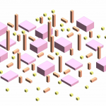
18 - Change the patterns to colors as shown in the screenshot below :
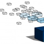
18 - Go back to the 3D view and select the objects you want to color. In the properties, add the color as a comment. In the s-text parameter, you can reference the grouping of objects.

19 - View the result in 3D

Lun, 18/11/2024 - 10:27
 Andrea Loddo
Gio, 14/11/2024 - 20:54
Andrea Loddo
Gio, 14/11/2024 - 20:54
A seguito i miei passaggi eseguiti per la realizzazione della seconda consegna:
- Seguo gli stessi passaggi presenti nel precedente post fino alla creazione dei parametri nei "Family Types" dove (facoltivavamente) aggiungo un nuovo campo testo nominato "s-name" in quanto può aiutare nelle fasi successive

- Il lavoro procede come nel post precedente: creo la composizione

- Nel menù "view" seleziono "Filters" e ne creo uno nuovo:
- Come nome gli assegno quello del colore che voglio ottenere per semplicità
- Nelle "Categories" seleziono "Generic Models"
- Nelle "filter rules" seleziono "comments" e "contains" e nella casella di testo scrivo lo stesso colore indicato come nome del filtro

- Sempre nel menù "View", apro "Visibilty / Graphics"
- Vado nella scheda "Filters"
- Seleziono "Add" e aggiungo tutti i filtri creati precedentemente
- Modifico la colonna "Patterns" selezionando il colore corretto in entrambe le caselle assicurandomi di aver selezionato come pattern "Solid fill"
NOTA BENE: Questa operazione va ripetuta per ogni singola vista nel quale voglio ottenere l'effetto

- Restando nel menù "View", seleziono "Schedules" e poi "Schedule / Quantities" creando una nuova tabella
- Seleziono "Generic models"
- Scelgo i parametri a me utili: nel mio caso "Family", "Type" e "Comments"
- Posiziono sia la tabella che il modello nella stessa schermata per visualizzare meglio ciò che svolgo
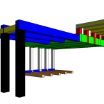
- Ora modificando la colonna "Comments" con i colori colori prima decisi i modelli selezionati cambieranno colore

- Questo il risultato ottenuto:

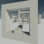
- Come svolto nella prima consegna, posiziono una camera posta ad 1.7 metri d'altezza

 Andrea Loddo
Gio, 14/11/2024 - 20:54
Andrea Loddo
Gio, 14/11/2024 - 20:54
A seguito i miei passaggi eseguiti per la realizzazione della prima consegna:
- Creo una nuova famiglia, selezionando dalla cartella "English" il template nominato "Metric Generic model";
- Creo due piani di riferimento, uno verticale e uno orizzontale con il comando "RP" o selezionando "Reference plane" nel menù "Create";

- Creo delle quote "Aligned" dal menù "Annotate" e collego i piani originali a quelli appena creati

- Creo un rettangolo dal menù "Create" selezionando "Estrusione", dopodichè collego i lati della appena generata estrusione con i reference plane usando il comando "Align", assicurandomi di bloccare gli allineamenti usando i lucchetti

- Seleziono la vista "front" dal Project browser, e lì creo un solo reference plane per collegare il lato mancante, seguendo i passaggi sopracitati
- Seleziono il comando "Family Types" sempre nella scheda "Create" e creo i tre parametri fondamentali: Lenght (Lunghezza), Width (Larghezza) e Thickness (Spessore); assicurandomi di selezione l'opzione "Instance", dopodichè creo anche eventuali Formule per legare i parametri tra di loro

- Selezionando le quote create precedentemente, associo ciascuna quota ad un parametro creato

- Apro di nuovo il menù "Family Types" e creo un nuovo tipo, modificando i parametri per quel tipo ad hoc per creare delle variazioni

- Questo il risultato ottenuto con questa prima estrusione

- Per questa consegna, ho creato anche una seconda estrusione con quattro parametri, oltre ai tre sopracitati, si aggiunge anche il parametro "offset", siccome l'oggetto sarà verticale, userò come piano principale il "front"


- Creo un nuovo progetto ed importo entrambe le famiglie nel progetto premendo "Import families" nel sottomenù all'estrema destra.
- Proseguo a creare la composizione usando le famiglie e i tipi importati

- Aggiungo una camera posta ad 1.7 metri d'altezza per accentuare l'effetto desiderato
