


 Alessia Notarangelo
Gio, 05/12/2024 - 19:45
Alessia Notarangelo
Gio, 05/12/2024 - 19:45
Apro Revit- families- new- Metric Generic Model face based- open. Aprendo il modello vedo che in 3D ho una “mattonella” su cui dovrò andare ad appoggiare la mia famiglia. In alto vado su Family Types- e aggiungo dei nuovi parametri: spessore e larghezza di tipo, lunghezza di istanza e li creo tutti come parametri condivisi- ok.
 Sul reference level mi creo due piani attribuendogli le quote S_Lunghezza e S_Larghezza, poi creo un’estrusione e la allineo a questi piani. Poi vado sulla vista front e creo il piano con quota legata al parametro S_Spessore e allineo l’estrusione a questo piano.
 Torno in alto a sinistra su Family Types e mi creo dei tipi, in questo caso:
 Salvo questa famiglia come: “NTT – Famiglia_Consegna_3”.Ora vado su File- New- Family- Metric Curtain Wall Panel- Open.
 Insert- Load Family- scelgo “NTT – Famiglia_Consegna_3”- Open.
Ora nel Project Browser trovo la mia famiglia tra i Generic Models e creo la mia composizione, allineando il primo oggetto al piano sulla sinistra. Si deve far attenzione che essendo una famiglia face based sarà possibile inserirla solo se la attacco ad un oggetto. Dopo aver creato una composizione salvo il progetto come: “NTT – Curtain Panel_Consegna_3”. Ora creo un nuovo progetto in cui inserire questo pannello: File- New- Project- Browser- “Default-Multi-Discipline_Metric”- Open- Ok.
 Elimino le parti del progetto che non mi servono, poi vado su Architecture- Wall e disegno un muro, poi allineo la linea d’asse con il piano orizzontale.
 Clicco sul muro, sulle Properties apro la tendina e rendo il muro un “Curtain Wall-Not Defined”.
 Clicco sul muro, sulle Properties faccio Edit Type- Duplicate- do il nome “NTT - Curtain Wall_Consegna_3”. Su Verical Grid metto Fixed distance, e poi metto come Spacing 1m- Ok.
 Insert- Load Family- “NTT - Curtain Panel_Consegna_3”- Open.
 Clicco sul Curtain Wall- Edit Type- su Curtain Panel metto la mia famiglia “NTT - Curtain Panel_Consegna_3”. Ok.
 Ora ho creato un Curtain Wall con la mia famiglia che si ripete, da cui posso fare una composizione.
 AgatheLeBrazidec
Gio, 05/12/2024 - 17:00
AgatheLeBrazidec
Gio, 05/12/2024 - 17:00
1- Create a Family:
Go to Create → Family → Select Curtain Wall Panel Metric as the template

2- Configure shared parameters via family type:
Add the following shared parameters:
S_Length
S_Width
S_Height

3- Import and position an existing family:
Open an existing family (square-shaped family)
Load this family into the newly created family
Position the imported element correctly

4 - Configure instance parameters:
Go to the family type of the square shape
Modify the parameters to set them as instance parameters

5 - Align the solid with the reference planes:
Align the solid with the reference lines (on the right and at the top)
Ensure that when the "EQ" distance changes, the right side of the solid moves, while the left side remains stationary

6- Create a type parameter:
Go to the family type of the new family
Add a new parameter named S_L.
Set the value of S_L to 2 m and confirm
7- Assign the parameter to the solid:
Select the solid
In the toolbar on the left, click on the square icon to the right of S_Length
Replace S_Length with S_L


8- Create a new project:
Go to Create → Project → Select Construction Template

9 - Create a curtain wall:
Create a reference plane
Create a wall of type Curtain Wall
In its properties, set the following options:
Layout → Fixed Distance with a spacing of 3000 mm


10 - Align the wall with a level:
Go to the South Elevation view
Keep only the Base T.O. Level visible
Move the wall to align it with the Base T.O. Level


11 - Load and apply the panel family:
Load the curtain wall panel family into the project
Select the wall in the project
In the type properties, set the family in the Curtain Wall Panel option

12 - Create a model line in the family:
Go to the Exterior view of the family
Go to Create → Model Line
Align the line with the left reference plane and the top and bottom points

13 - Add a visibility parameter:
Add a new parameter in the type properties:
Name: Line
Data Type: Yes/No
Click on the line you created and, in the toolbar, check the square icon next to Visible
Load the family into the project


14 -Control the visibility in the project:
In the project, when the element is selected, uncheck Line in the properties to make the line invisible

15 -Load a face-based family:
Open a face-based family type
Load this family into the curtain wall panel family
16 -Position a face-based element:
In the 3D view, position a face-based element
Align this element with the reference lines
Load the family into the project
17 -Add a reference plane and align an element:
In the curtain panel family, go to the Exterior view
Add a horizontal reference plane
Place a face-based element and align it with this reference plane.
18 - Annotate the height:
Annotate this alignment by creating a S_Height tag
Verify that when the reference plane is moved, the solid moves accordingly


19 - Create a schedule:
Go to View → Schedules and Quantities
Select the Curtain Wall Panel category
20 - Add custom fields:
Add S_Height as a field
21 - Test the height variation:
Modify the heights of the panels in the schedule to verify that the elements respond correctly

=> Here is my final project, for instruction 3:
Gio, 05/12/2024 - 17:03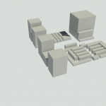 Dimitri Della Casa
Dom, 01/12/2024 - 22:32
Dimitri Della Casa
Dom, 01/12/2024 - 22:32
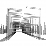
Buongiorno, la mia idea progettuale è la vista aerea dell'Ex Mattatoio, del quale ho provato a riprodurre la varietà degli elementi che lo compongono.
1-Creo una nuova famiglia sul software Revit del tipo "Metric Generic Model" 2-Creo due piani di riferimento perpendicolari attraverso il comando "Reference plane" in "Create"
 3-Creo 3 nuovi parametri Tipo in "Family Types", chiamandoli rispettivamente "lunghezza", "larghezza" e "altezza"
 4-Parametrizzo i piani di riferimento, connettendoli con i nuovi parametri creati
 5-Realizzo la pianta dell'oggetto creando un rettangolo con il comando "Extrusion" in "Create" e parametrizzandone i lati, ovvero li vado a allineare, attraverso il comando "Align", con i piani di riferimento e li blocco con gli appositi padlocks
 6-Realizzo i passaggi 4 e 5 anche nell'alzato, aiutandomi con la visione a sinistra "left"
 7-Realizzato il volume, posso crearmi tutti i "Types" che mi servono per la composizione, dando ad ognuno le adeguate dimensioni (si deve tenere conto che i "Types" sono tutti collegati, quindi al variare di uno, si modificheranno tutti gli altri Types); infine salvo la famiglia


 8-Per realizzare invece oggetti in cui la variazione del singolo non comporta quella degli altri, creo una "New Family" nella quale compio gli stessi passaggi della precedenti, utilizzando però i parametri condivisi ("Shared parameter") e l'impostazione "instance"; infine salvo la famiglia
 9-Apro "New Project" e vi carico entrambe le famiglie create, così da poter realizzare la composizone sia con i "Types" che con le "Instance"; dopodiché attivo le ombre per realizzare il planivolumetrico.
 10-Infine le viste assonometrica e prospettica danno maggiormente idea della spazialità e della volumetria della composizione

Dom, 01/12/2024 - 23:54
 Francesco Di Gennaro
Sab, 30/11/2024 - 11:32
Francesco Di Gennaro
Sab, 30/11/2024 - 11:32
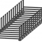
Buonasera, scrivo questo post per far vedere i provedimenti attraverso il quale ho creato la mia composizione tettonica attreverso il curtain wall panel. Per prima cosa ho aperto una nuova famiglia : Families -> Metric curtain wall panel

Succesivamento ho aggiunto dei shared parameters alle proprietà della famiglia : Family properties -> new -> shared parameter -> "C_L e C_W" -> instance

Ho inserito un'estrusione a cui poi ho associato i parametri condivisi C_L e C_W; Allineare il solido alle linee di riferimento (a sinistra e in alto): quando si cambia la distanza di "EQ" il lato sinistro del solido si muove con esso ma il lato destro non varia.

Nellla vista Left ho applicato il shared parameter C_L per un lato della mia estrusione; nel mio caso era l'altezza e l'ho resa un instance in modo che dopo nel mio progetto potrò renderla variabile.

Succesivamente ho inserito una famiglia face place da me creata precedentemente nella mia famiglia curtain wall panel; cioe sta a significare che la trave sarà sempre connessa a l'elemento verticale che ho appena creato; puoi vincolare la trave dove vuoi, nel mio caso ho connesso la trave 20x20 nella parte superiore del mio pilastro e la trave 50x20 nella parte intermedia.


Ho scelto poi di aggiungere un parametro yes/no alla trave orizzontale intermedia che mi permettesse di farla vedere o meno : new -> parameter properties -> shred parameter ->name : show -> data type : yes/no

Dopodiché ho aggiunto la mia famiglia ad un nuovo progetto : creare -> progetto di costruzione
Sul progetto creo una composizione muraria di Curtain Wall, tuttavia cambio le sue type properties duplicando il type e dandogli un nuovo nome; a questoo nuovo type inserisco la mia famiglia sul parametro "Curtain Panel" : click on wall -> properties -> Curtain Wall -> Edit Type -> Type ->Duplicate -> Curtain Panel -> "FRS - curtain panel consegna3".

Sulla categoria Horrizontal Grid metto una distanza fissata : Layout -> Fixed distance -> 1000.0mm


Creo una schedule in cui pongo i miei parametri "C_L e show" in mod tale da poter modificare l'altezza della mia famiglia e se voglio far vedere o meno le travi orizzontali: View -> Schedules ->new -> category Curtain Panels -> Available fields -> "C_L" e "show"


Sab, 30/11/2024 - 16:39
 elisa.vit
Gio, 28/11/2024 - 20:43
elisa.vit
Gio, 28/11/2024 - 20:43
1. Open a new Family and select the type "Metric Curtain Wall Panel" template in the English library. Save your new Family.
2. Creating the column part :
In that Family, create a new extrusion. Lock the position of your extrustion on the Reference Planes in the Ref. Level.
Add a new reference plane in the front view and define a dimension (quotation) between this new reference plane and the existing bottom reference plane.
Align the top and bottom sides of the extrusion with their respective reference planes and lock the alignment.
Create a new parameter by defining a shared parameter of type 'occurrence' and naming it 'Column Height'. Associate this parameter with the quotation.
3. Creating the beam part :
Open a face based family previously created. This ensures that the new beam will always remain connected to the vertical element you just created.
It is a Metric Generic Face-Based model with one shared occurrence parameters: Length.
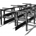
Here we place the beam on the top of our column.
In front view create one more vertical reference plan. Align the beam to existing and new vertical reference plan and lock.
Create a quotation between these two.
Create a new parameter by defining a shared parameter of type 'occurrence' and naming it 'beam length'. Associate this parameter with the quotation.

4. After saving the Curtain Wall Panel family, open a new project and select the architecture template.
In the project, draw an architectural wall and then change its type to a Curtain Wall.
Insert the Curtain Wall family you just created into the project.


Then, go to 'Modify Type,' duplicate the Curtain Wall, and give it a new name.
- Change the panel type to your curtain wall family
- Add a vertical grid to the curtain wall with a fixed spacing. Choose a specific value for the spacing.

5. Create a new schedule that includes the 'beam length' allowing you to modify the lenght of the horizontal elements. 

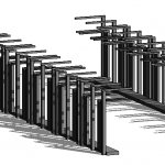
Here, we adjust the length of the beams to achieve a graceful shape.
But we can also edit the height of the columns. To do so we create a new schedule that includes the 'column height' allowing you to modify the lenght of the vertical elements.

We then adjust the walls until we achieve a satisfying result.
 Here, we added another Curtain Wall family, which is visible on the sides.
Ven, 29/11/2024 - 00:21