


 Matteo Cucciniello
Ven, 25/10/2024 - 18:55
Matteo Cucciniello
Ven, 25/10/2024 - 18:55
1)Creo una nuova famiglia> reference plane>alligned dimension> family types> new paramater>creo lato e altezza>extrusion. Ho un oggetto quadrato che non ha rapporto di proporzione.
2)Creo una nuova famiglia> reference plane>alligned dimension> family types> new paramater>creo lato e altezza> formula altezza= lato*4/5> estrusion. Cambiando i parametri delle dimensioni creo un’altro tipo. In definitiva ho un oggetto di base quadrato con due tipi chiamati 4 metri e 10 metri. Le proporzioni sono uguali.
3) Creo una nuova famiglia> reference plane>alligned dimension> family types> new paramater>creo lato e altezza> formula altezza= lato*4/5>extrusion. In questo caso i parametri sono impostati come istanze. In sede di progetto le dimensioni sono cambiate singolarmente. si conservsano i rapporti di proporzionalità.
4) Creo una nuova famiglia> reference plane>alligned dimension> family types> new paramater>creo lunghezza, larghezza e altezza> formula altezza= lunghezza/10>formula larghezza= lunghezza/100>extrusion.Cambiando i parametri delle dimensioni creo un’altro tipo.
5)Dopo aver salvato tutte le famiglie le importo sul progetto. Disegno la composizione e imposto la vista.

 Elisa Esposito
Ven, 25/10/2024 - 08:40
Elisa Esposito
Ven, 25/10/2024 - 08:40
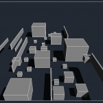
Per la realizzazione dell'esercitazione è stata scelta la seguente prospettiva la quale rappresenta la visuale di una persona che si avvicina ad una piccola metropoli :

Come prima è stato creato un piano di riferimento, dopodichè sono stati creati 6 nuovi parametri con misure diverse e, con il comando "estrusione", sono stati creati i vari tipi di parallelepipedi collegati ai parametri precedentemente creati:


Dopo la creazione di ciò, è stato aperto un nuovo file "modello" nel quale sono state caricate le nuove famiglie, posizionate in pianta e sistemate, poi, in vista 3D sistemato ulteriolmente in modo da giocare con le ombre, successivamente con il comando "camera" sono stati realizzati i seguenti screen:


 AmelieMoy
Ven, 25/10/2024 - 09:22
AmelieMoy
Ven, 25/10/2024 - 09:22
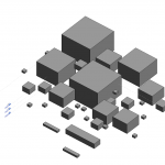
1. Create a family, draw perpendicularly two reference planes on reference level
2. Put the dimensions that connect the base plane to the reference plane
3. In family type, create 3 settings : length/width/height
4. Associate the labels with the different measurements for each of the dimensions and lock everything, length and width on the reference plan and height on the front
5. Create an extrusion then align to the new reference plane
6. In family type: put for height: width*2/3
7. Create new family types: 8m/3m/10m...
8. Create a project and load the family (cube) and place the shapes by changing the types randomly
9. Then in the family change family type and check occurrence and register as a new family
10. Load this family back into the project
11. Replace the cubes everywhere
12. Add some/one level(s), then lift some of the cubes
13. In nomenclature add to Family and Type in the list
14. Obtaining an assembly: different sizes of cubes, at different heights, in different locations
Ven, 25/10/2024 - 09:28
 Stefano Gilardi
Ven, 25/10/2024 - 08:40
Stefano Gilardi
Ven, 25/10/2024 - 08:40
Buongiorno , per l'esercitazione assegnata ho scelto questa prospettiva :

Ho realizzato uno pseudo Empire State Building con grattacieli di varia forma e tipologia sullo sfondo .
Per iniziare ho realizzato una famiglia partendo da un semplice cubo come effettuato in classe.

dopo di che sono andato avanti a modificare le proprietà dei vari tipi :


dopo aver creato una serie di type '' Grattacielo'' mi sono concentrato sull Empire state building :


Dopo aver realizzato l'ultima antenna ho assemblato tutto e creato la mia vista con il comando camera ad un altezza di 12 metri d'altezza .
Ven, 25/10/2024 - 09:24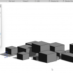 Justine Musielinski
Ven, 25/10/2024 - 09:15
Justine Musielinski
Ven, 25/10/2024 - 09:15
1.Nouveau ->créer une famille -> English -> metric generic model
2. Créer 2 plans de référence un vertical et un horizontal ->reference plane
3.Annoter -> alignée afin d’avoir les côtes
4.Enregistrer la famille : « TPP - rendufamille »
5.Type de familles -> ajouter nouveau paramètre « longueur » puis « largeur »
6.Cliquer sur la côte et définir le libellé « longueur » et « largeur »
7.Créer une extrusion -> tracer un rectangle
8.Aller dans aligner -> cliquer sur la ligne de référence puis sur celle du solide
9.Dans vue de face ajouter un plan de référence -> annoter, aligner
10.Aligner ligne de référence avec le solide
11.Type de famille -> ajouter nouveau paramètre -> hauteur
12.Cliquer sur la côte -> définir le libellé hauteur
13.Dans type de famille -> créer 3 nouveaux types différents -> longueur 5/10/15m
14.Aller dans fichier ->créer ->projet->gabarit architectural
15.Charger la famille dans le projet
16.Placer des solides dans le projet
17.Dans type de famille-> formule ->hauteur-> « =largeur*2/3 »
18.Charger dans le projet
19.Placer différents types de famille
20. Aller dans arborescence -> famille -> modèles génériques -> faire glisser dans le projet
21.Aller dans élévation -> changer le niveau de certains blocs
22.Aller dans famille -> type de famille -> modifier l’occurence pour la hauteur la longueur et la largeur
23. Fichier -> enregistrer sous -> famille -> »rendufamille occurence »
24.Charger dans le projet -> ajouter différents types avec occurence
25.Changer dimensions des types avec occurence directement dans le projet
26.Aller dans vue -> nomenclature/quantités->modèle générique ->ajouter famille puis type
27.Tri et regroupement -> modifier -> ajouter famille et type puis sélectionner ligne vierge entre les deux
28.Activer ombres
1. New -> create a family -> English -> metric generic model
2. Create two reference planes, one vertical and one horizontal -> reference plane
3. Annotate -> aligned to have dimensions
4. Save the family: "TPP - family render"
5. Family types -> add new parameter "length" and then "width"
6. Click on the dimension and define the labels "length" and "width"
7. Create an extrusion -> draw a rectangle
8. Go to align -> click on the reference line and then on the solid
9. In the front view, add a reference plane -> annotate, align
10. Align the reference line with the solid
11. Family type -> add new parameter -> height
12. Click on the dimension -> define the label height
13. In family type -> create 3 new different types -> length 5/10/15m
14. Go to file -> create -> project -> architectural template
15. Load the family into the project
16. Place solids in the project
17. In family type -> formula -> height -> "=width*2/3"
18. Load into the project
19. Place different family types
20. Go to the project browser -> family -> generic models -> drag into the project
21. Go to elevation -> change the level of some blocks
22. Go to family -> family type -> modify the occurrence for height, length, and width
23. File -> save as -> family -> "family render occurrence"
24. Load into the project -> add different types with occurrences
25. Change the dimensions of the types with occurrences directly in the project
26. Go to view -> schedules/quantities -> generic model -> add family and then type
27. Sorting and grouping -> modify -> add family and type, then select a blank line between them
28. Enable shadows
Ven, 25/10/2024 - 09:20