


 eugenio clementi
Dom, 06/05/2018 - 16:26
eugenio clementi
Dom, 06/05/2018 - 16:26
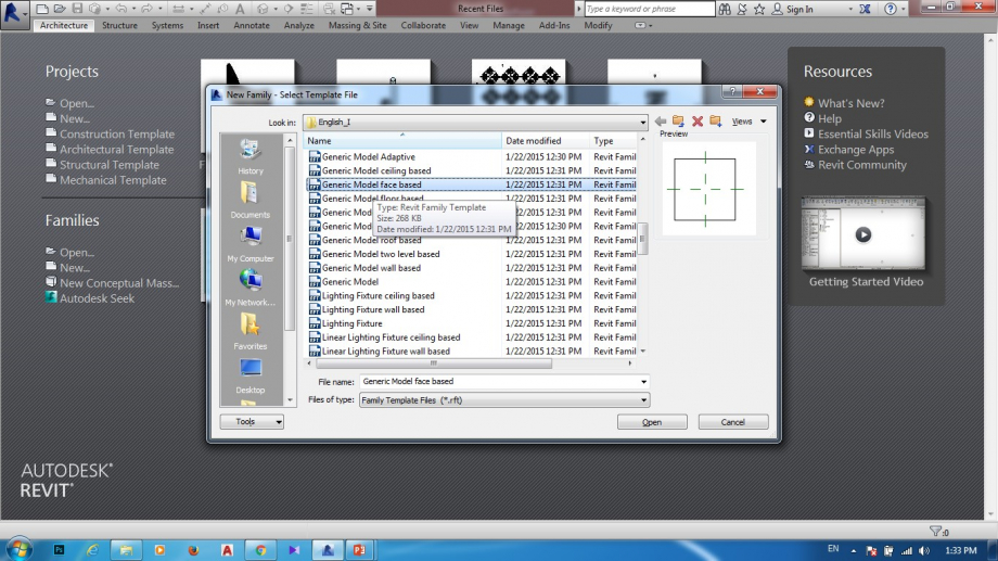
Apriamo Revit, poi:
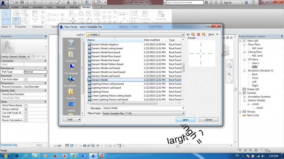
Family > New> Metric Generic Model
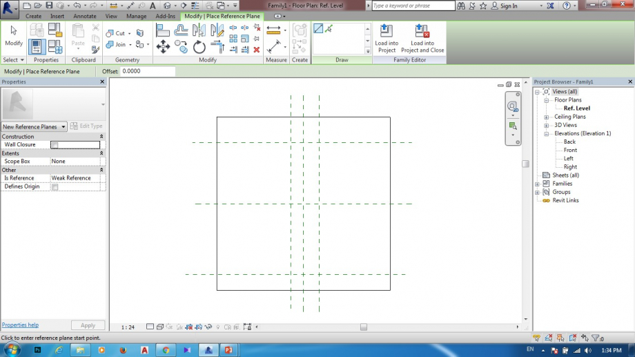
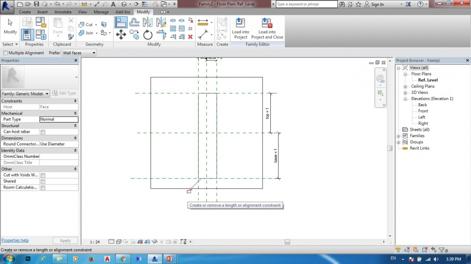
Reference plane
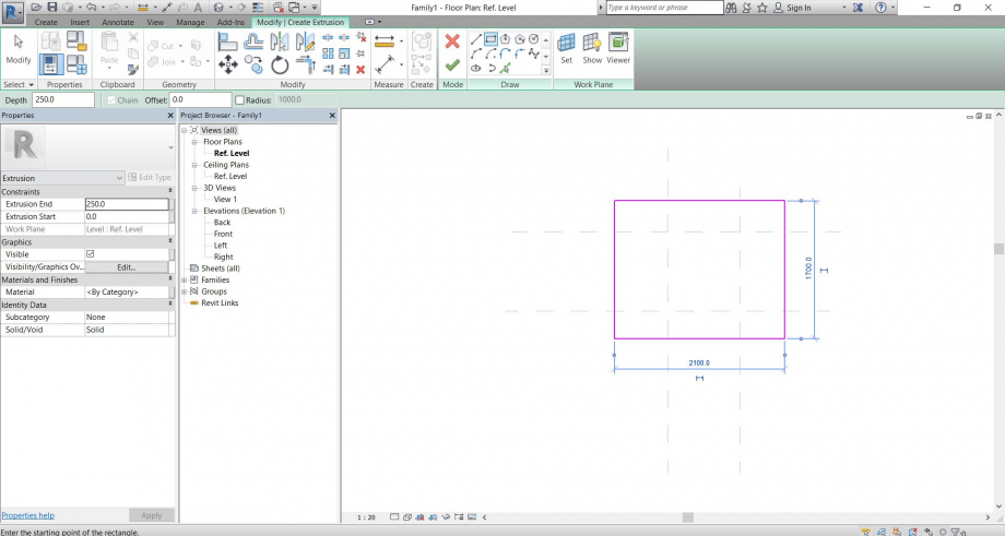
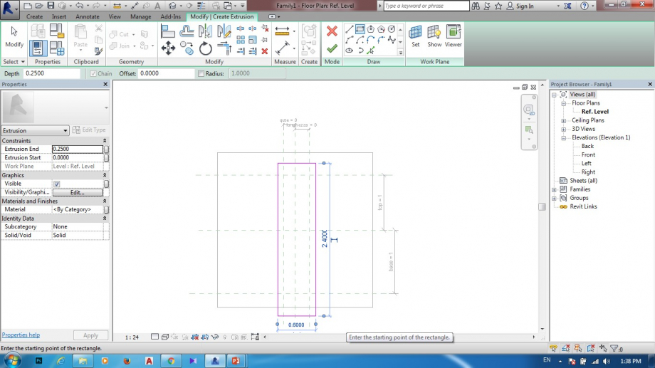
Create > Extrusion > Rectangle > Finish Edit Mode
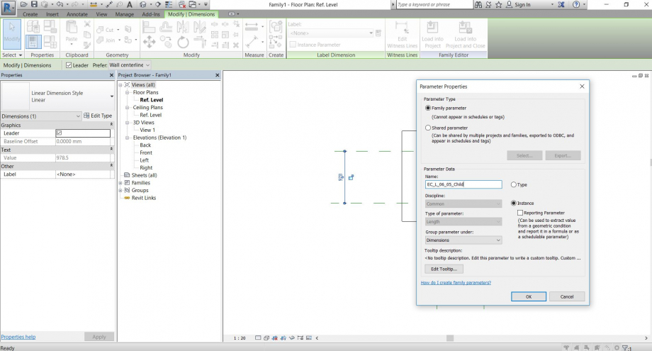
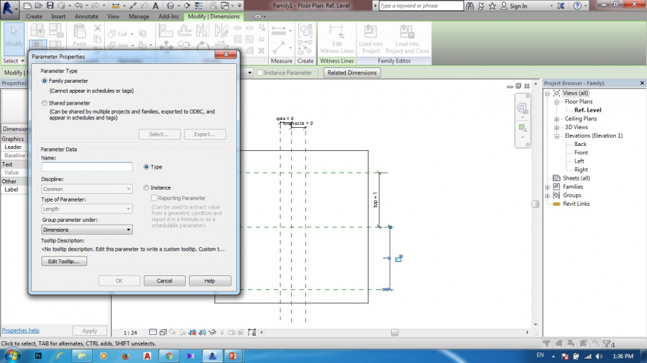
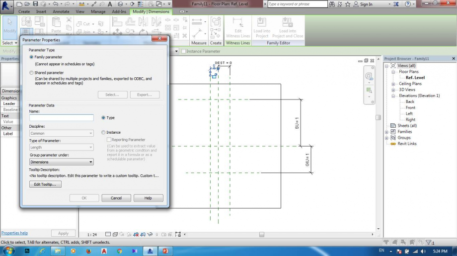
Annotate > Aligned > Label > Create parameter
Align (allineo il rettangolo ai piani di riferimento, chiudo il lucchetto)
In elevation creo un altro piano di riferimento con il suo parametro

Ho creato dunque un file “child” che contiene la gamba del tavolo

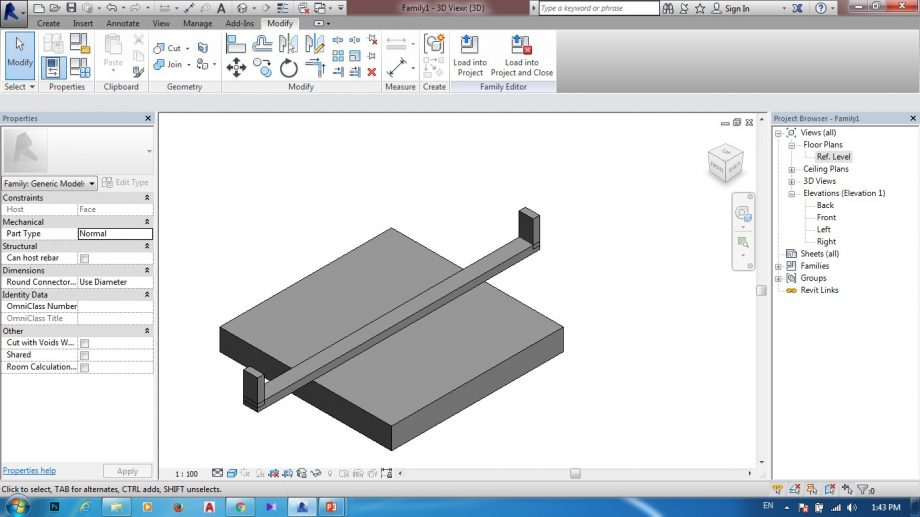
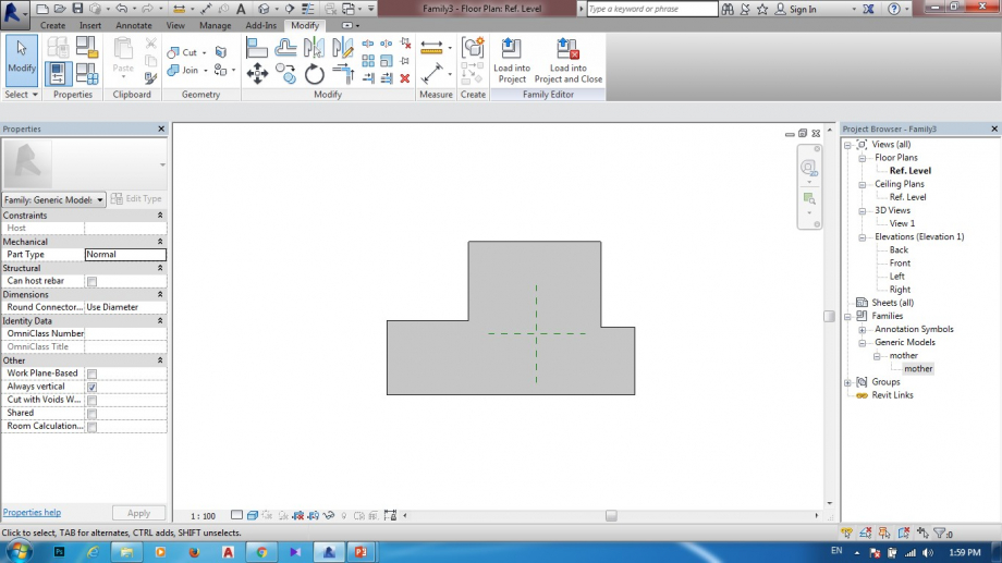
Creo un altro file family, sarà la “mother” del nostro "child"

Ripeto le operazioni per creare un parallelepipedo, stavolta sto creando il piano del tavolo. Creo tre parametri di istanza: Larghezza, Lunghezza, Altezza

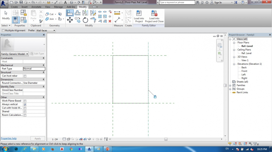
Torno nel file “child” e lo carico nel “mother”, allineo l’oggetto child (la gamba del tavolo) agli opportuni piani di riferimento e chiudo il lucchetto, in maniera tale che successivamente, al variare dei parametri - quindi allo spostarsi dei piani di riferimento - la posizione delle gambe del tavolo cambierà opportunamente, rimanendo sempre ancorata all’angolo del tavolo.

Prima di inserire il tavolo in un file project, cambio la natura dei parametri e da Family Parameter li modifico in Shared Parameter, tutto questo mi permette di modificare i parametri direttamente dalle schedules del file project.

Apro un file project e carico il file “mother”

Creo una schedule e setto i parametri Altezza, Larghezza, Lunghezza del tavolo.

Dal Generic Model Schedule posso modificare i 3 parametri e generare qualsiasi tipologia di tavolo. Posso in questa maniera creare un tavolo dalle dimensioni personalizzate per poi riprodurlo infinite volte.


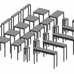
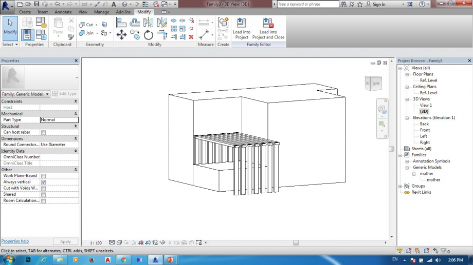
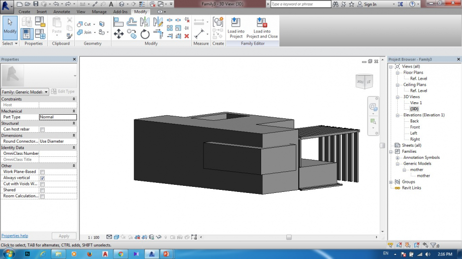
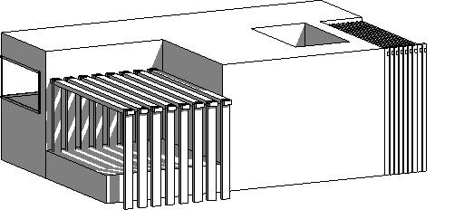
Composizione “infinite forme per infinite quantità”,
un' ESPOSIZIONE DI TAVOLI “CUSTOM” ad un Salone del mobile.
Dom, 06/05/2018 - 16:51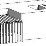 FATEMEH GHADIRIJAVID
Dom, 06/05/2018 - 02:34
FATEMEH GHADIRIJAVID
Dom, 06/05/2018 - 02:34
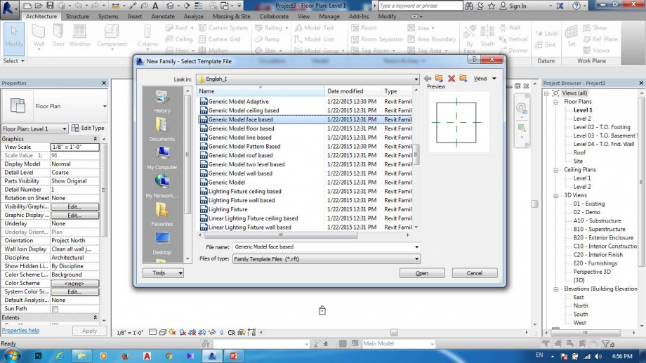
1.APRO UNA NUOVA FAMIGLIA DI GENERIC ODEL FACE BASED
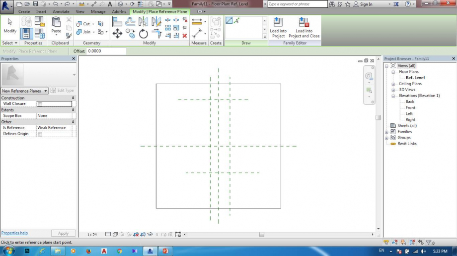
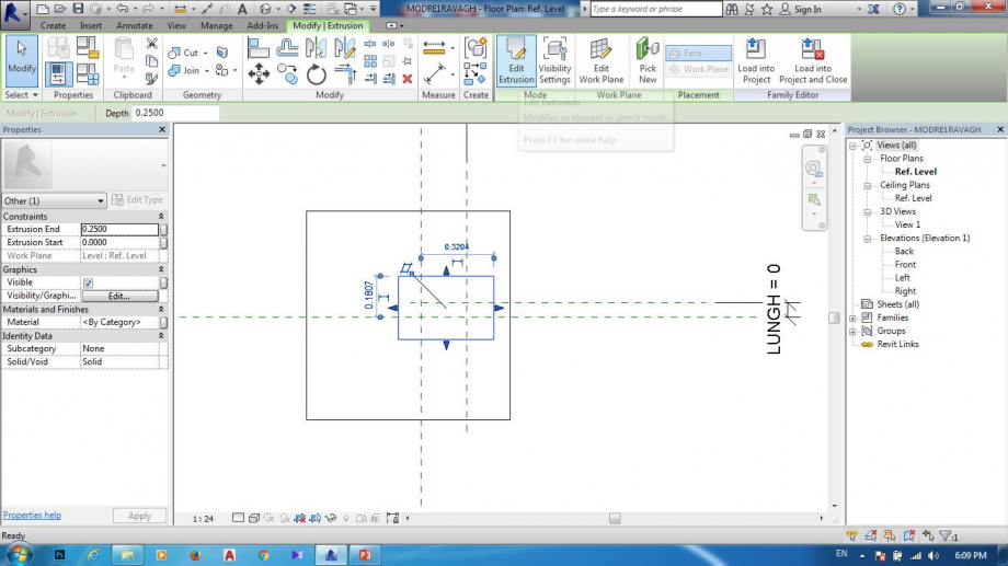
2.DISEGNO PIANO DI RIFERIENTO PER DEFINIRE BASE DI DISEGNARE MODELLO CHE POSSO SCRIVERE RP O POSSO ANDARE SUL CREATE E POI REFERENCE PLANE CHE UGUALE ,DISEGNO PIANO DI RIFERIMENTO COE FOTO
3.CARATTERIZZO TUTTI DIMENSIONI CHIAMO LUNGHEZZA E LARGHEZZA ...
4.DISEGNO UN MODELLO CHE VOGLIO AVERE
5.INCOLLO TUTTO CON ALIGN
 5.DISEGNO ALTRO MODELLO CHE VOGLIO AVERE SUL PIANO DI BASE
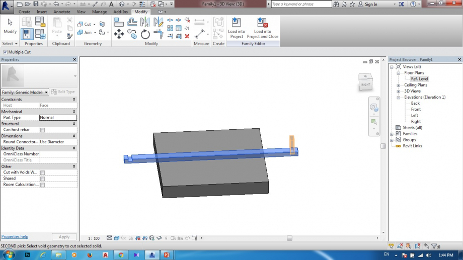
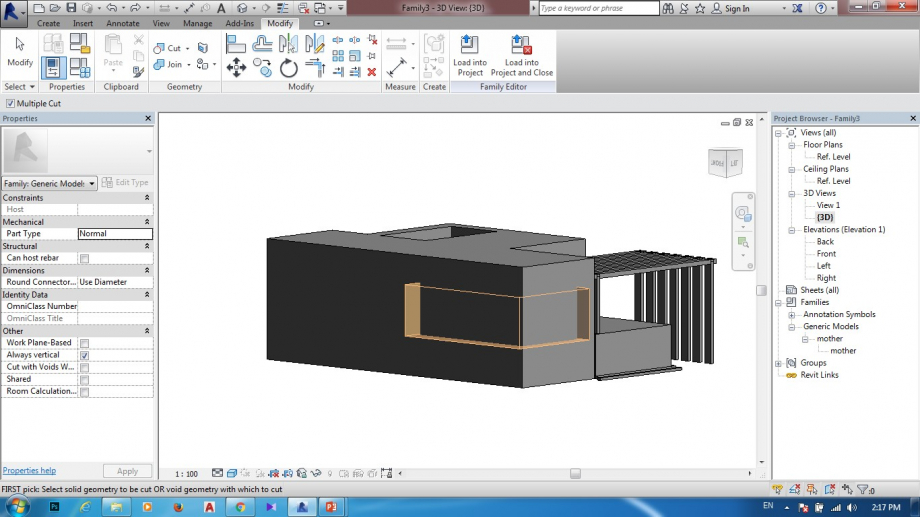
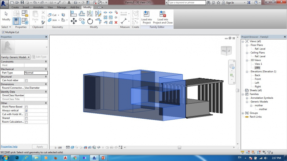
6.E POI COMNCIO PER FARE CUT CHE PRIMA DEVO CAMBIARE IDENTITA DI MODELLO CHE STAVO SOLIDO DEVO CAMBIARE CON VOID E POI FACCIO CUT
7.APRO UNA NUOVA FAMILY DI BASE GENERIC MODEL E POI FACCIO PIANO DI RIFERIMENTO COME SEMPRE CHE VOGLIO AVERE MODELLO DI QUELLO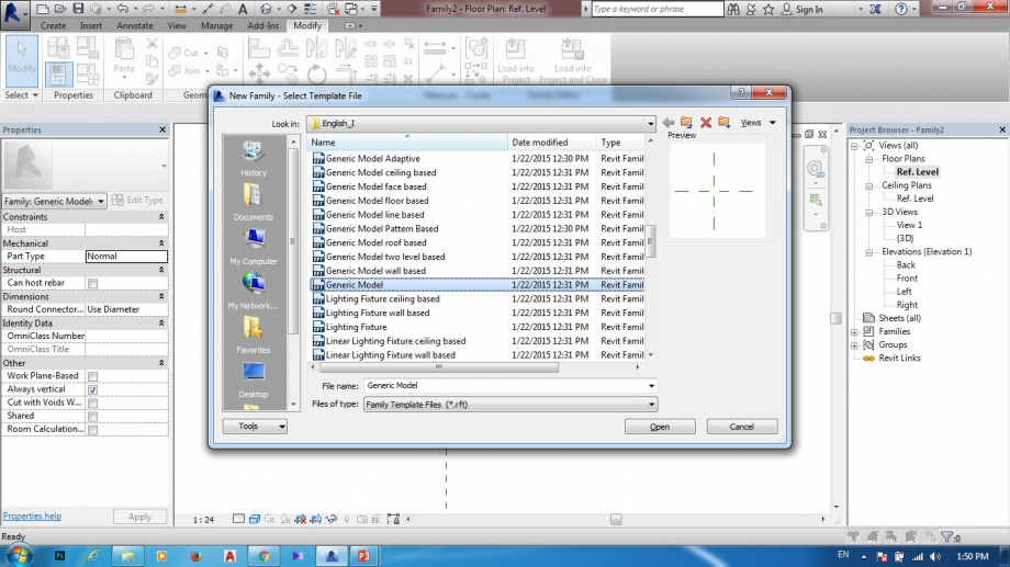
8. E POI DISEGNO MODELLO CHE VOGLIO AVERE E DOPO INCOLLO TUTTO CON ALIGN
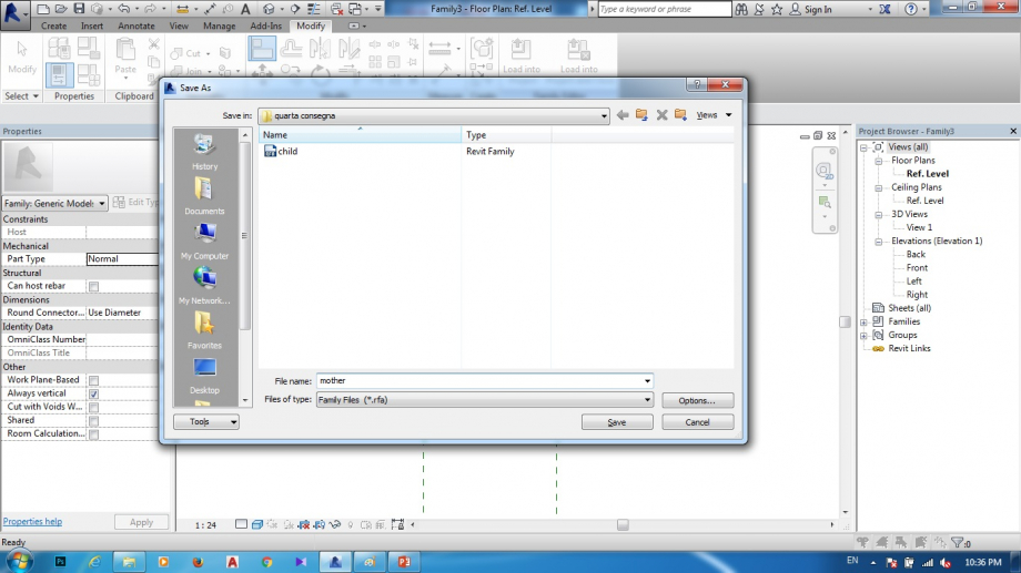
 9.SALVO FILE CON NOME MODRE
 10.IMPORTO FILE CHILD NELLA FILE DI MODRE CON LOAD INTO PROGECT
11.APRO UNA NUOVA FAMILY GENERIC MODEL
17.DISEGNO UNA FORMA GEOMETRICO CON LINEA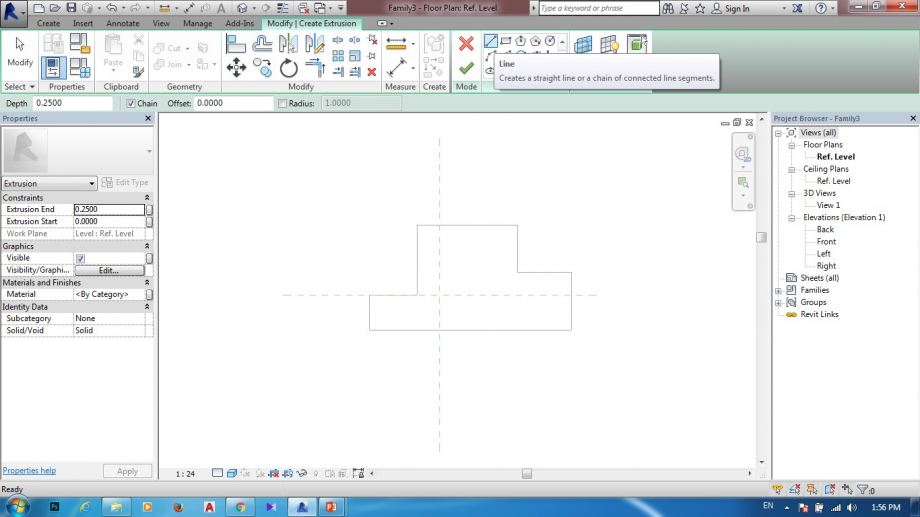
18.IMPORTO FILE MODRE NELLA NUOVA FILE FAMILY ''LOAD IN TO PROJECT''
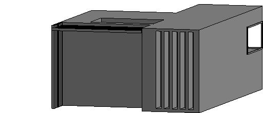
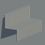
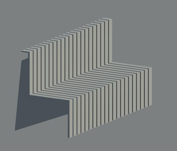
19.FACCIO COMPOSIZIONE DIVERSE
20.E POI FACCIO ANCHE FACCIO CUT PER AVER FINESTRE
21.UN PO CAMBIO IMPORTO ANCHE ALTRE FAMOGLIE CHE HO FATTO
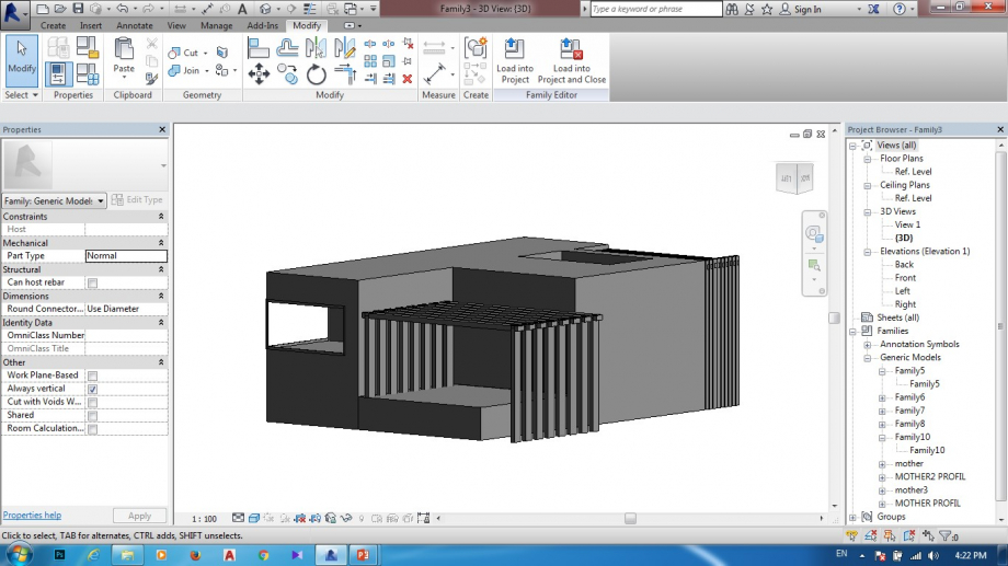
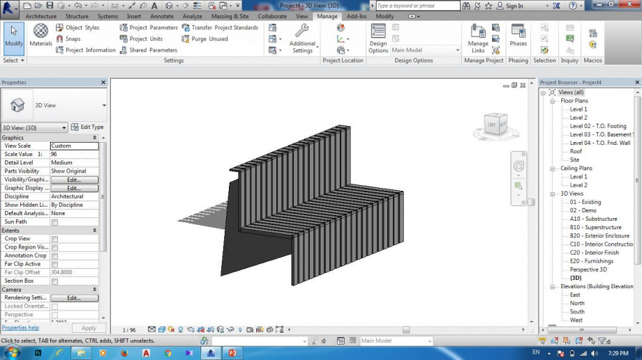
22.E ALLA FINE POSSO PORTARE TUTTO NELL NOUVO PROJECT
Dom, 06/05/2018 - 03:25
 AMIR GOLCHAY
Dom, 06/05/2018 - 01:38
AMIR GOLCHAY
Dom, 06/05/2018 - 01:38
1.prima apro una nuova family ''Generic Model face based
2.faccio definire piano di riferimento per modello geometrico che voglio disegnare ,vado sul Create sul Reference plan o posso scrivere RP dopo di che vado per disegnare piano di riferimento
3.adesso faccio caratterizzare piani di riferimenti per avere dimensione piu preciso
4.disegno modello che voglio avere 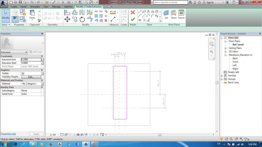
5.incollo tutto con align posso anche scrivere align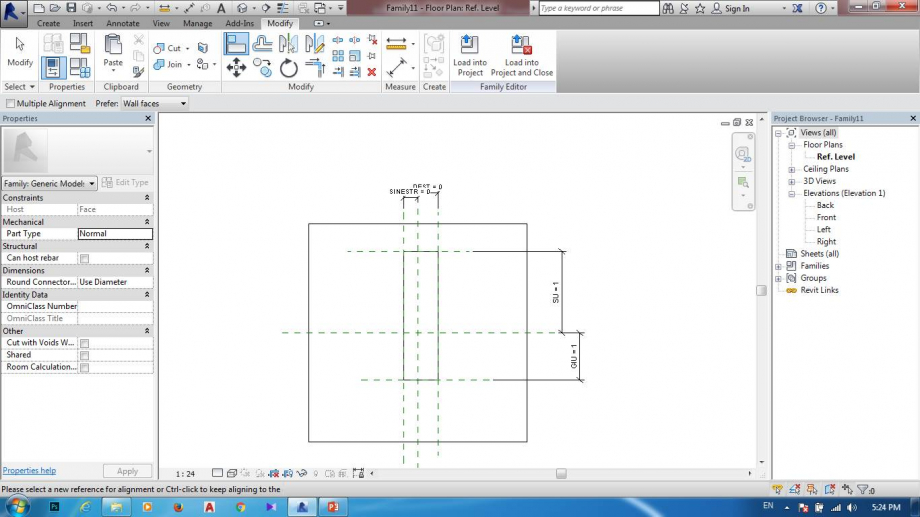
6.e poi disegno un altra modello sul primo che hofatto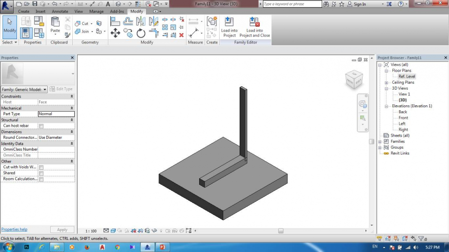
7.voglio tagliare quello modello devo cambiare carattere di modello che prima era solido devo cambiare con void che diventa giallo quello che voglio tagliare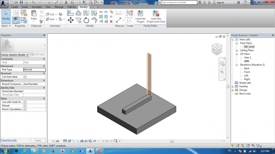
8.e poi faccio cut scelto prima quello che voglio dopo quello che non voglio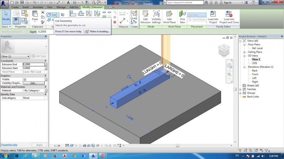
9.salvo file con nome child perche quello deve andare per incollare un file piu completta questo un pezzo di un file assemblaggio.
10.apro una nuova famiglia generic model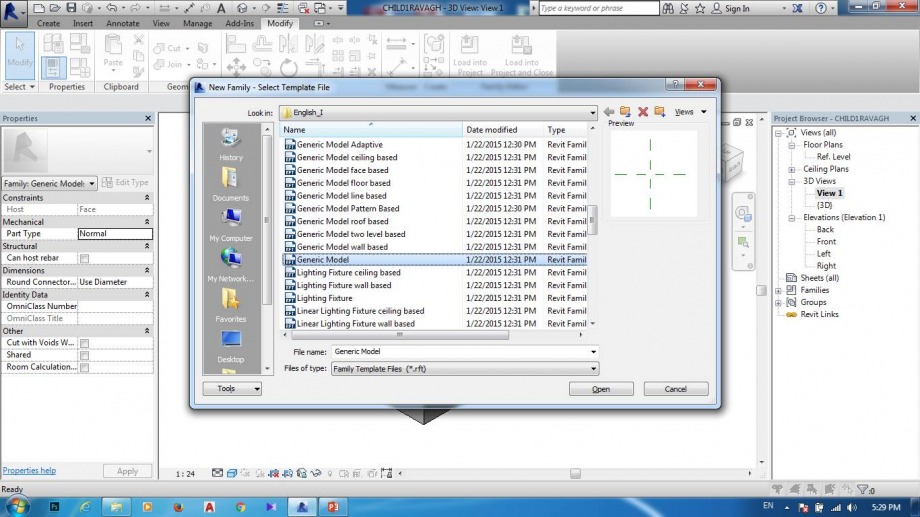
11.e poi faccio piano di riferimento anche caratterizzo tutto per aver dimensione preciso.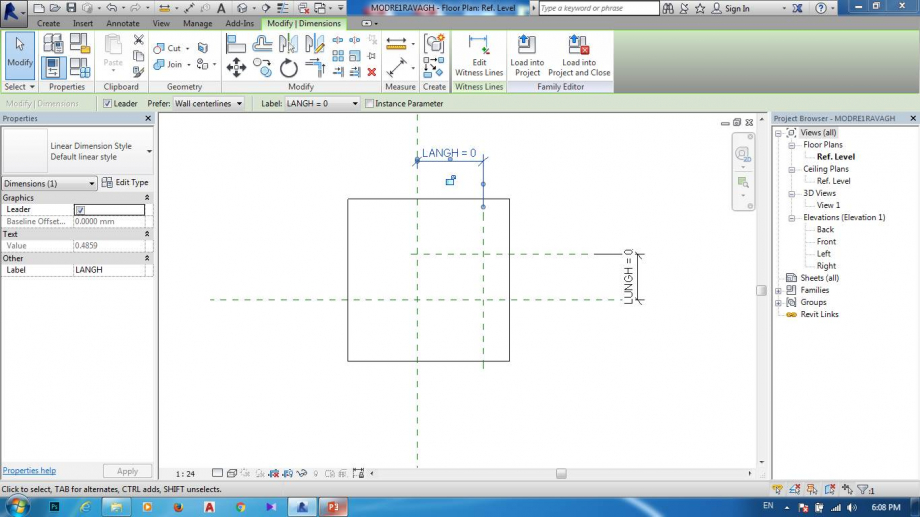
12.disegno un modello geometrico
13.importo modello child di file mother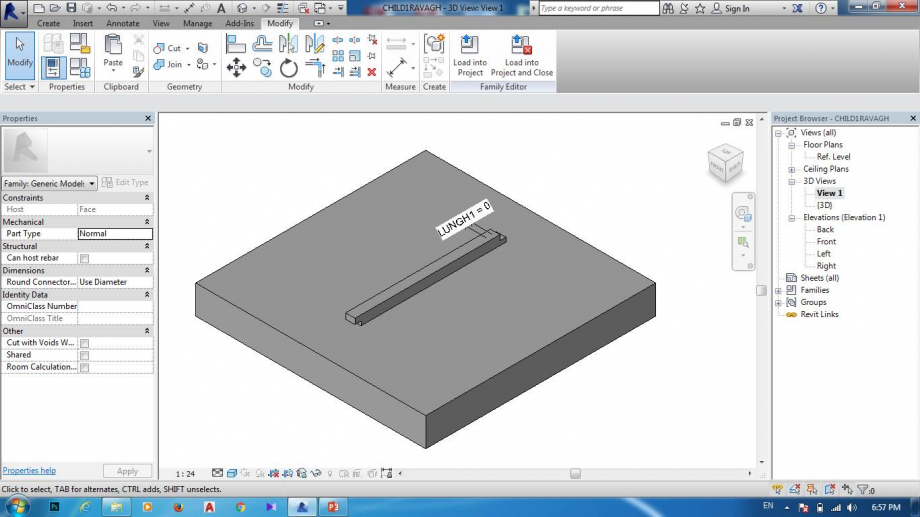
14.faccio load in to project clicco sul nome file che voglio importare child di la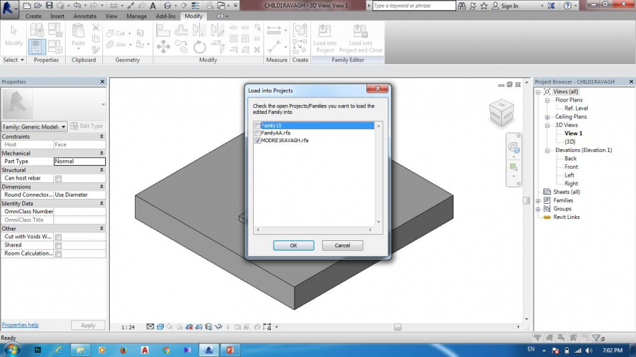
15.file di mother diventa cosi un pezzo di un file assemblaggio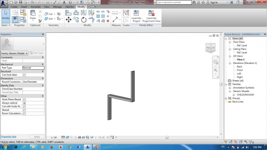
16.apro una nuova file Generic model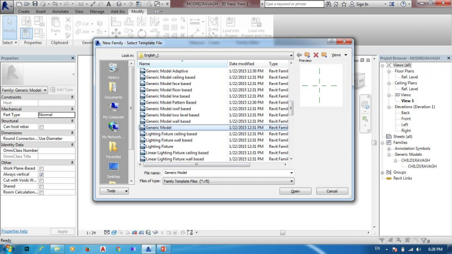
17.disegno questa volta con linea che ce sul create e poi extrusion ,disegno un modello che voglio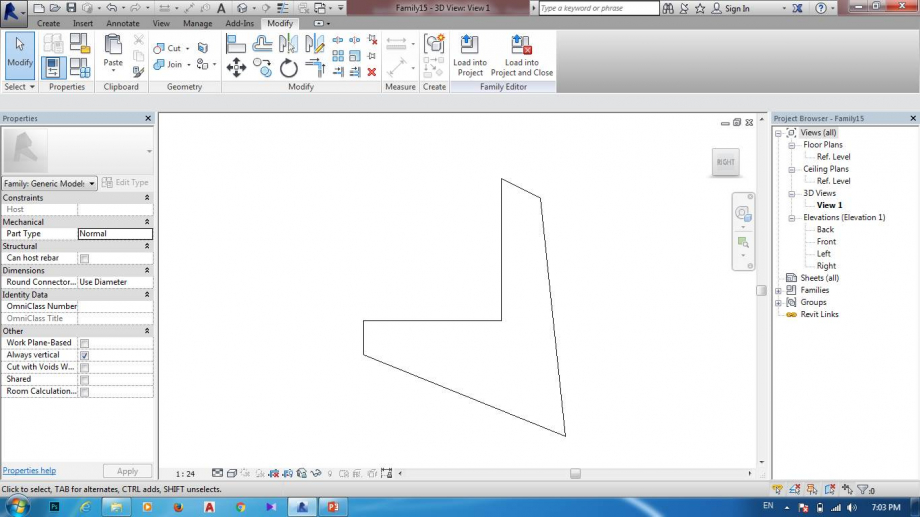
18.impporto file di mother di nuova family che apertoàà faccio load into project e poi clicco sul quell file che voglio importare di la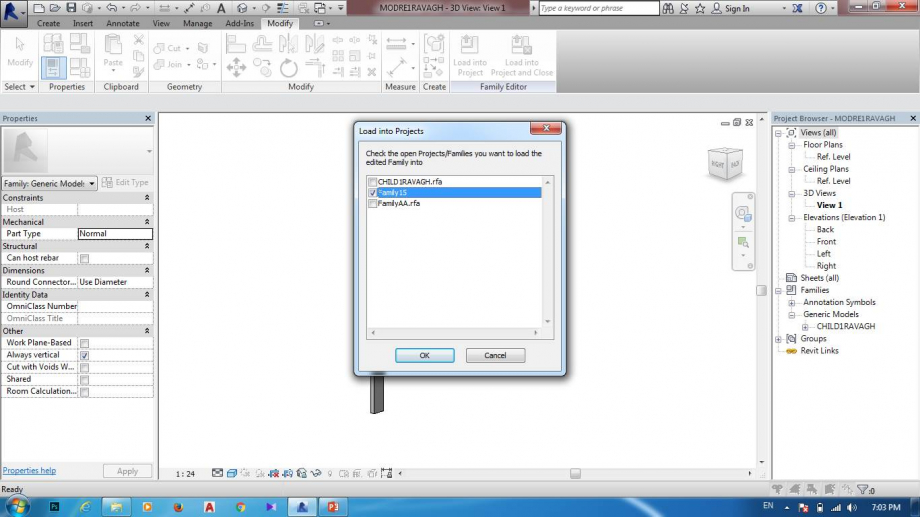
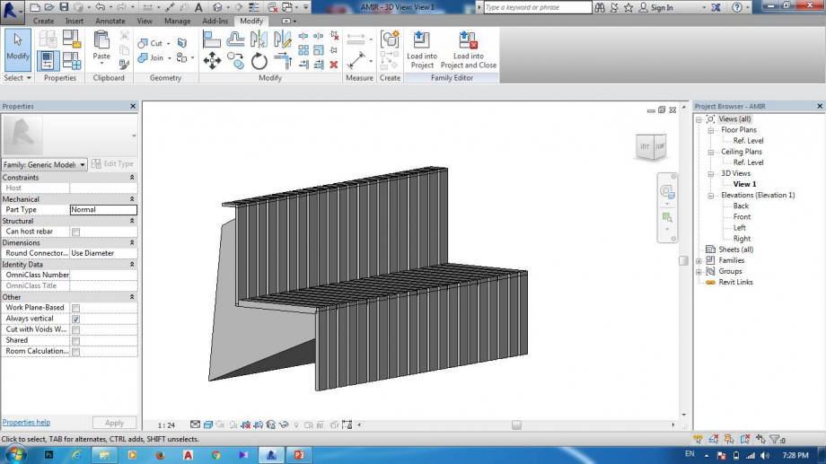
19.comincio per fare composizione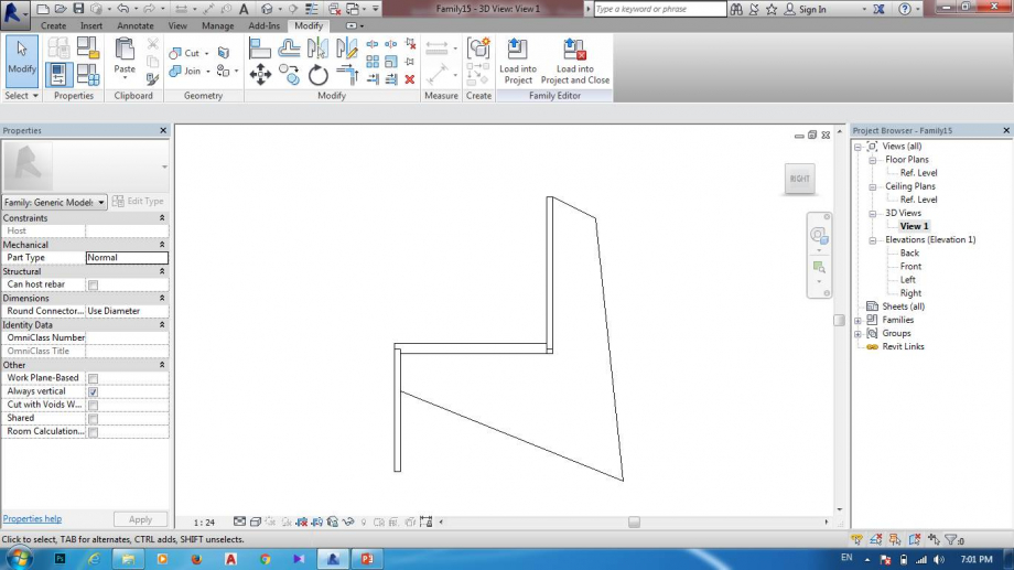
20.anche io ho importato altri file che ho fatto come lo stesso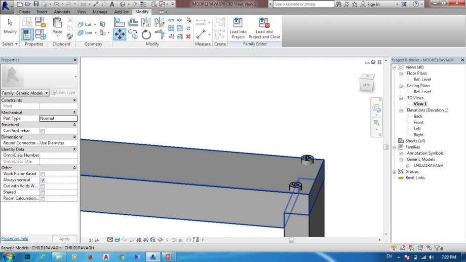
21.file lultima diventa cosi

Dom, 06/05/2018 - 02:21
 Ana Klainsek
Sab, 05/05/2018 - 14:46
Ana Klainsek
Sab, 05/05/2018 - 14:46
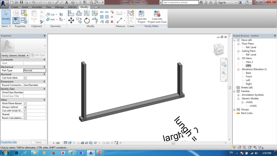
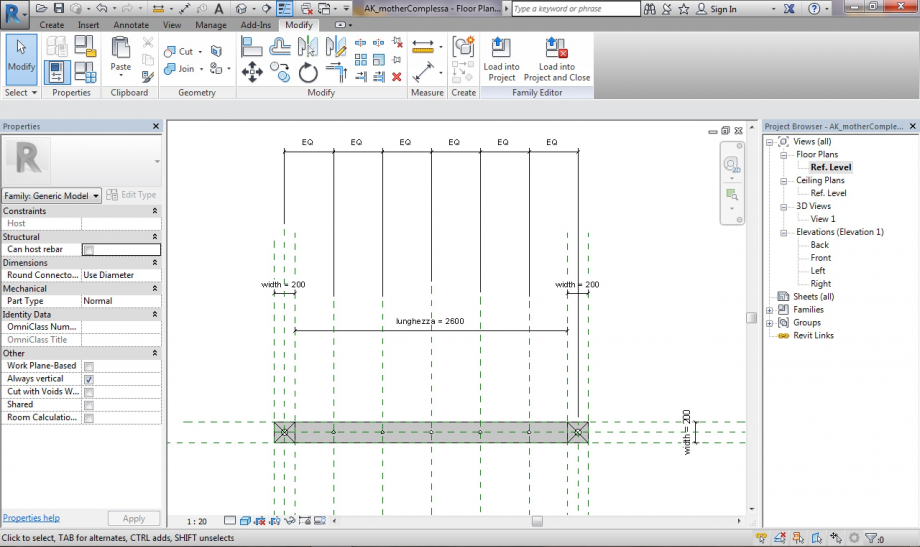
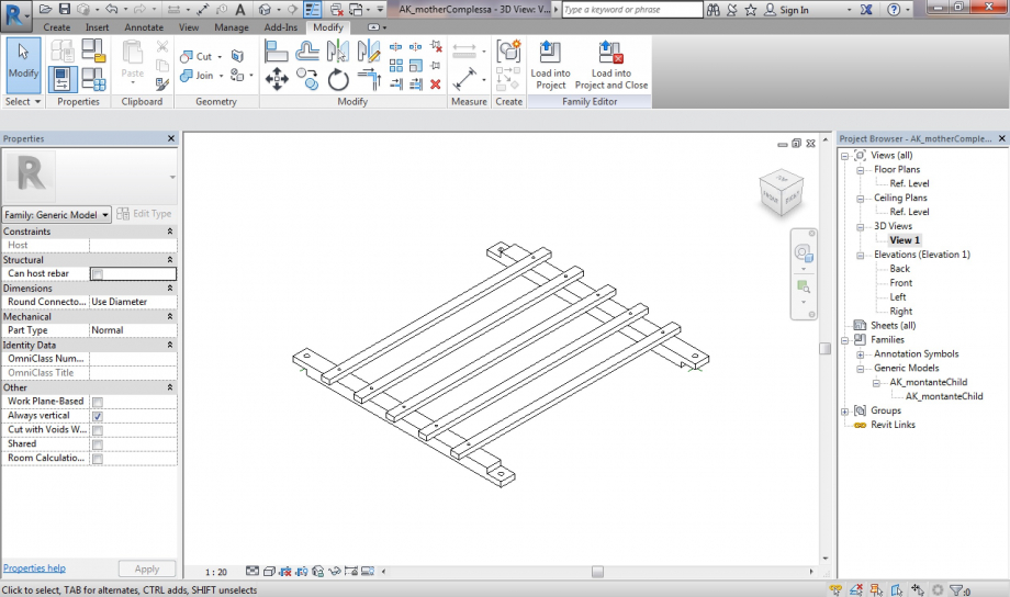
- First I created a new Metric generic model for the mother: a bar with aligned sides to reference planes with parameters for the width and the length. At both sides of the bar a portion of the same length and width would be half of the bar’s height and positioned each on opposite heights, so that afterwards each mother could be mounted on another one.
- For the holes, I created circle extrusions in equal intervals, making a void out of them and cutting them out of the bar.
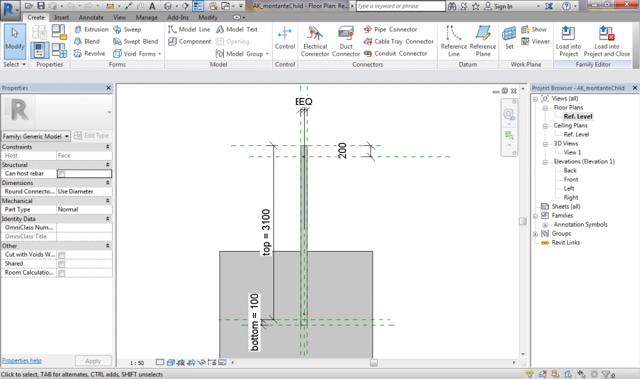
- For the child I opened a new family - metric generic model face based (template to make things be in contact to one another)
- I created a bar that would go on top and between two mother bars linked through the holes on each side created the same way as in the mother, and positioned it centered at the crossing point of the two initial reference lines of the generic model so that it would be easier to position on the mother
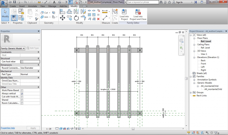
- Then I loaded the child into the mother’s file, which needs to be in contact with the mother object, and created a composition piece
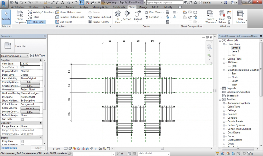
- I loaded the mother file with the composition piece into a new project and copied several pieces rotating them and mounting them on each other. The composition can keep growing mounting elements on the sides this way
Sab, 05/05/2018 - 15:00
 Ana Klainsek
Sab, 05/05/2018 - 14:35
Ana Klainsek
Sab, 05/05/2018 - 14:35
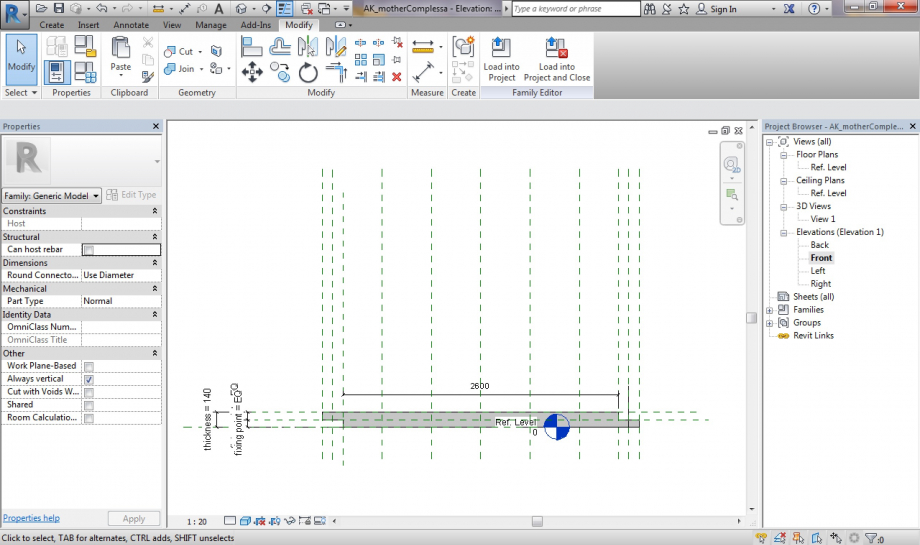
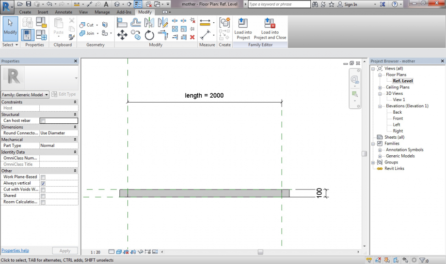
- I created a family file on a metric generic model for the „mother“ part of the composition, which consists of a horizontally oriented bar with a fix length and width and a variable height, for which I created the shared parameter s_thickness
- On another metric generic model I created the corresponding child, which would be a vertically placed bar with a fix height (half of the mother's) and the same fix width of the mother, while its thickness would be the shared parameter of the mother
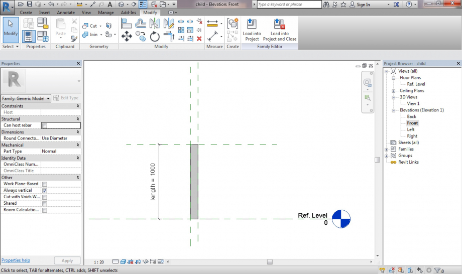
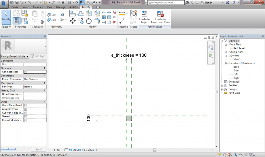
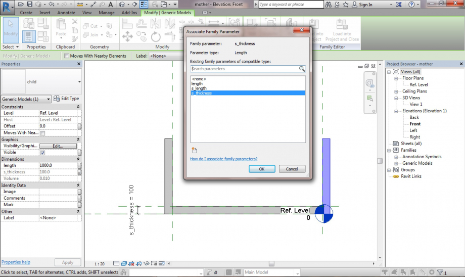
- I loaded the child into the mother’s file and positioned a child on each side of the mother. To fix the shared parameter of the child to the mother’s, I associated the parameters under Properties of the child, so that they would vary together.
- On a new project, where I loaded the mother with the children, I created a composition through a regular variation on the thickness parameter of a row of assembly pieces.