 Siamak_Kavoosi_Far
Ven, 04/05/2018 - 18:20
Siamak_Kavoosi_Far
Ven, 04/05/2018 - 18:20
Tectonic Composition
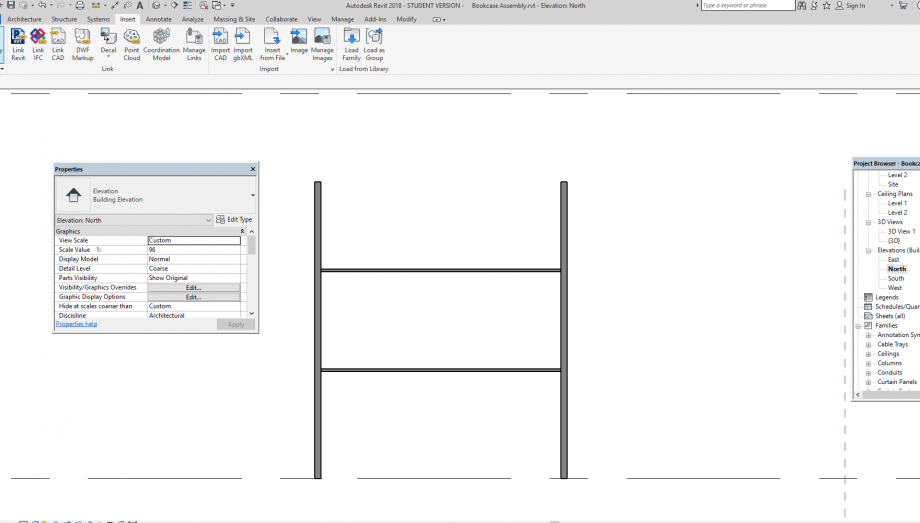
In this delivery I tried to practice a kind of composition in which there are some different part (Families) which are assembled together in project file

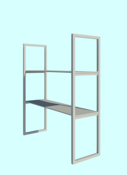
I am going to compose a bookcase, this bookcase is made of different small parts, so I create this small part separately as FAMILY and the unit them in ASSEMBLY phase. The parts are:
- The supports
- Connection beet ween supports
- Shelves.
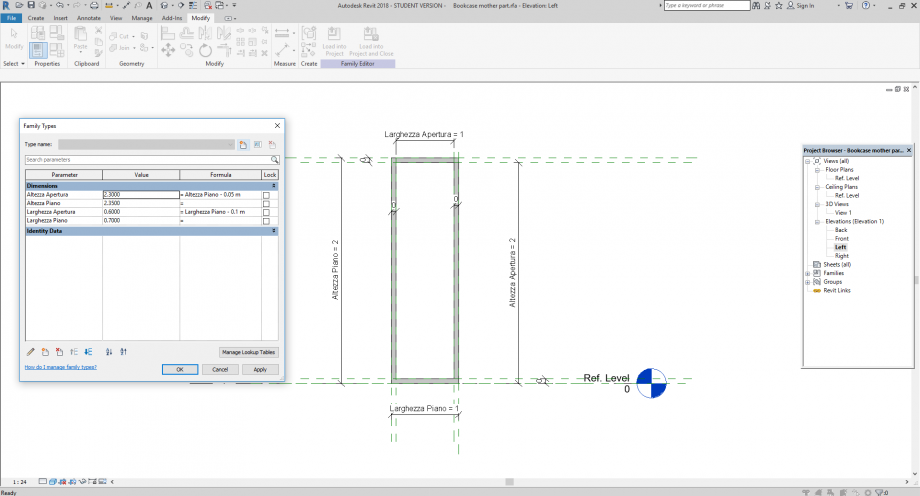
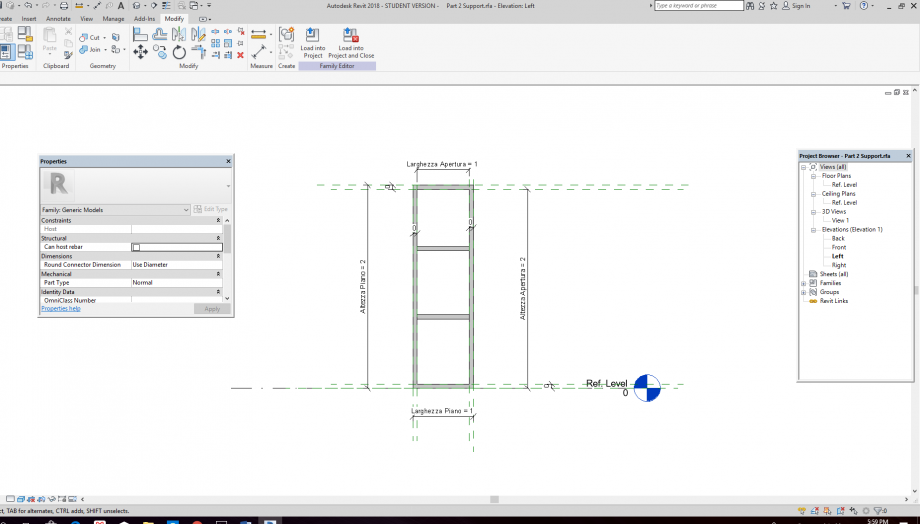
The Supports: can be considered as MOTHER PART
For creating the support in choose the GENERIC MODLE family.
I create 4 parameters: Support Height + Support Width + Void Height + Void Width and fixed thickness,
Connections between supports: can be considered the CHILD 1 PART
for this part I need GENERIC MODEL FACE BASED family
it has fixed height and width; the only parameter is the LENGHTS
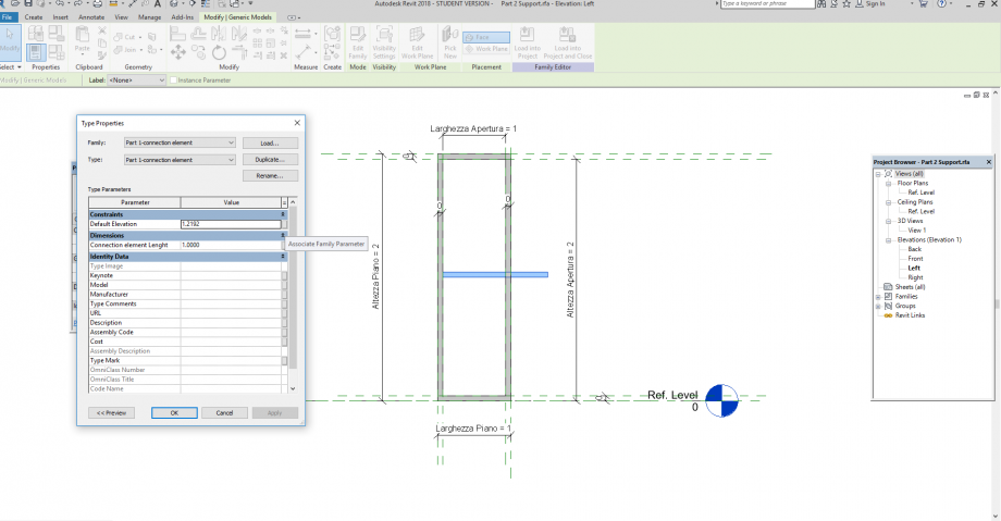
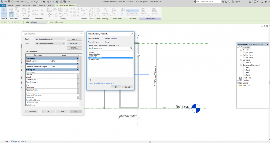
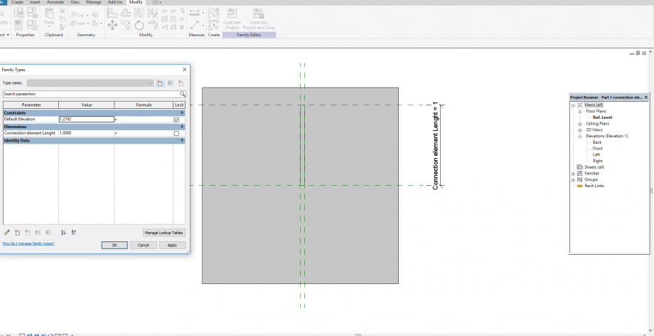 I INSERT THE CHILD PART IN THE mother file and create association between the WIDTH of the support and the length of CONNECTINO ELEMENT
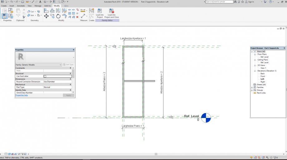
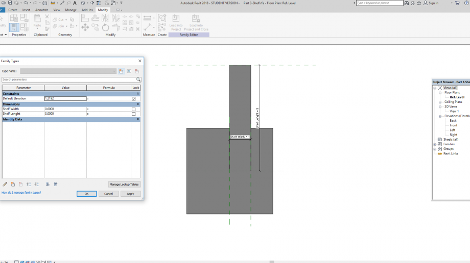
Now I have to model the Shelf: It’s an independent part
Also, for shelves I chose GENERIC FACE BASED family
The parameters of this family are the LENGTH AND WIDTH while the thickness is fixed.
Now it’s the time of assembling all the parts in ASSEMBLY project file. In insert mother and child together as on object.
The last step is inserting the SHELV family and assemble to the project
 Elea Clancier
Ven, 04/05/2018 - 13:56
Elea Clancier
Ven, 04/05/2018 - 13:56
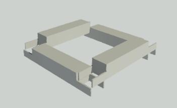
For the third exercise, I used a shared parameter to do variations of the width between mother and child.
I made first a child with a rectangular geometry with the width as a shared parameter.
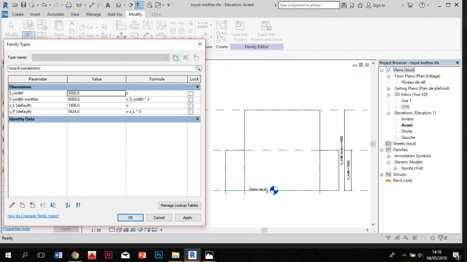
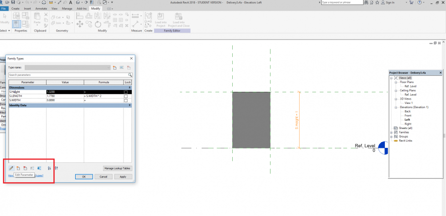
Then I loaded it into a mother element, also rectangular. Here I wanted the width of the mother twice the one of the child so I indicated in the family type window "S_width mother = S_width*2".
Then I created an assembly of this element in which mother and child where linked each others. I puted them as they could be assemblated each other and fixed them using reference lines.
Then I played on the variation of the width and saw that mother and child evoluated together.
 Siamak_Kavoosi_Far
Ven, 04/05/2018 - 11:16
Siamak_Kavoosi_Far
Ven, 04/05/2018 - 11:16
The main aim of these delivery in learning the capacity of creating shared parameters in a family which can be listed in the schedule in our project file in Revit.
-The first step is creating a basic family, I choose GENERIC MODEL FAMILY, then I begin with creating the necessary REFRENCE PLANE:

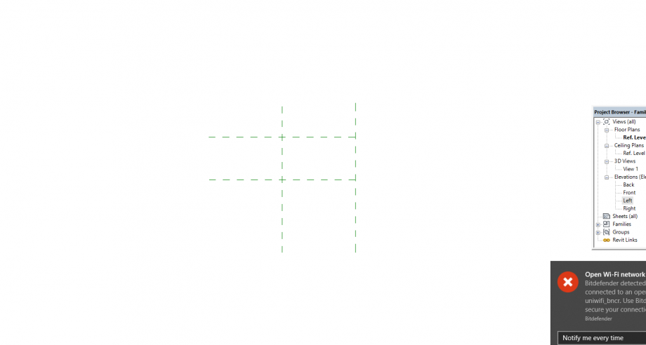 -Now the ANNOTATIONS
-I create my PARAMETERS using the ANNOTATIONS. I create TYPE PARAMETERS
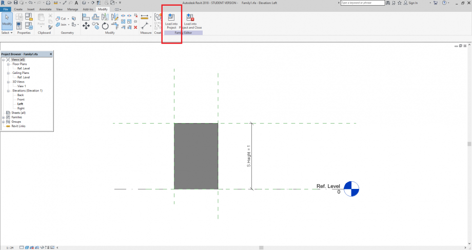
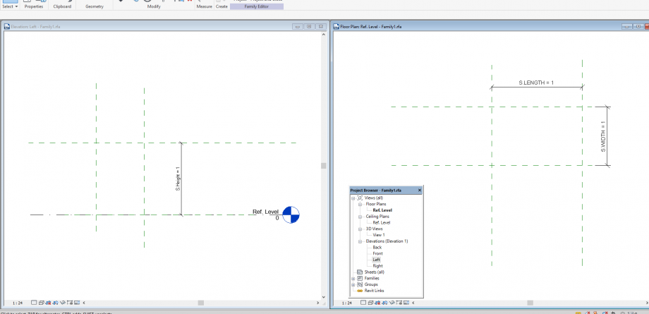 -Now my parameters are ready, and I can begin my model, I’ve created 3 parameters, S. LENGTH-S. WIDTH-S. HEIGHT. I also created my S. HEIGHT in function of S. WIDTH.
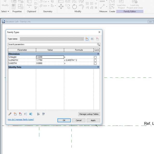
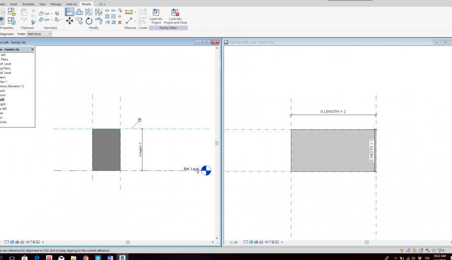
-Extrusion, selecting the rectangle mode, and OK extrusion, after closing the extrusion mode I can align the volume with the REFRENCE PLANES.
-Now my family is ready to be loaded in the project but before I need to create a PROJECT FILE.
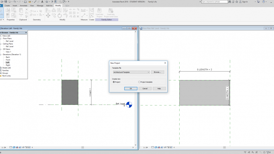
-There 2 ways for inserting a family into project:
1) From the FAMILY environment: LOAD TO A PROJECT:
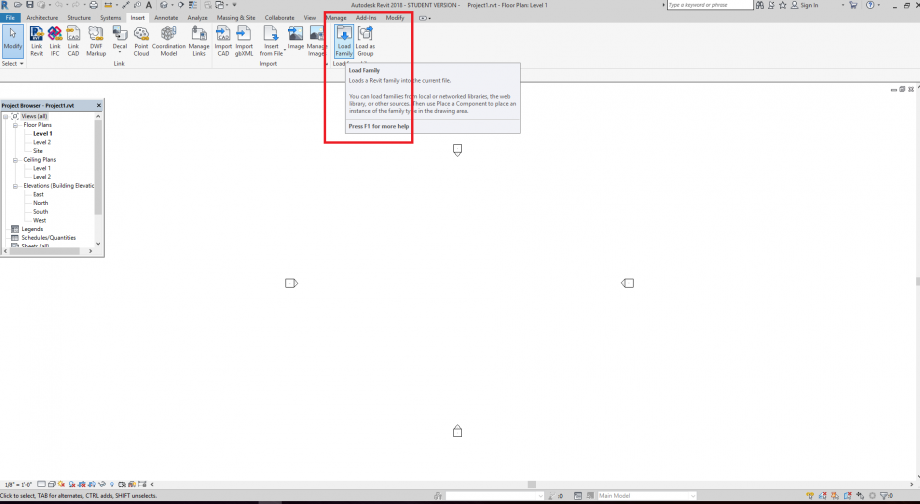
2) From the PROJECT environment: INESERT-LOAD FAMILY, then drag it form the list in the PROJECT BROWER.
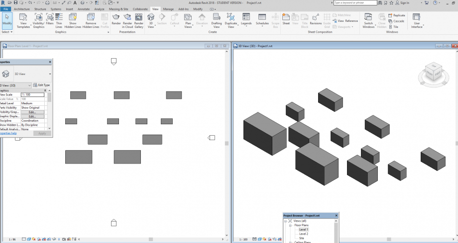
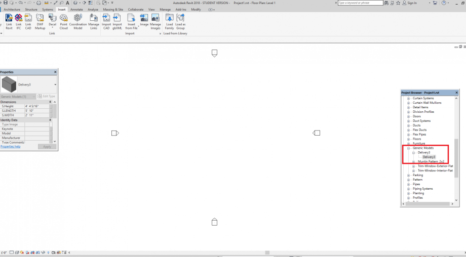 -Now I have can copy my FAMILY and create different TYPES.
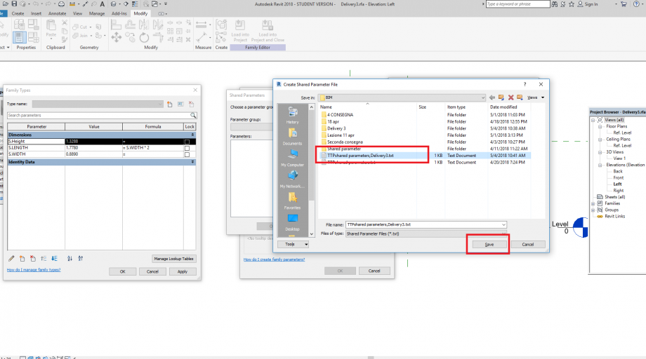
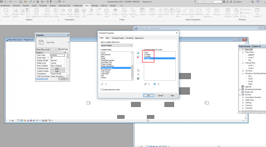
-Now I need the schedule: VIEW – SCHEDULES- SCHEDULES/QAUNTITIES, choose the GENERIC MODEL as CATEGORY, and now I can choose which parameters insert into my schedules, but I can’t find none of the parameters created in the family because they are the FAMLIY INTERN PARAMETERS:
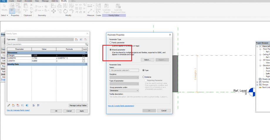
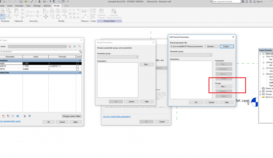
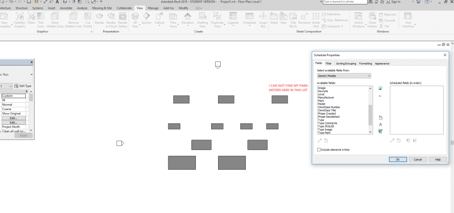 to find them in this list I need to change them to SHARED PARAMETERS. To do it I have to came back to FAMILY file.
I change the parameters from FAMILY PARAMETERS to SHARED PARAMETERS.
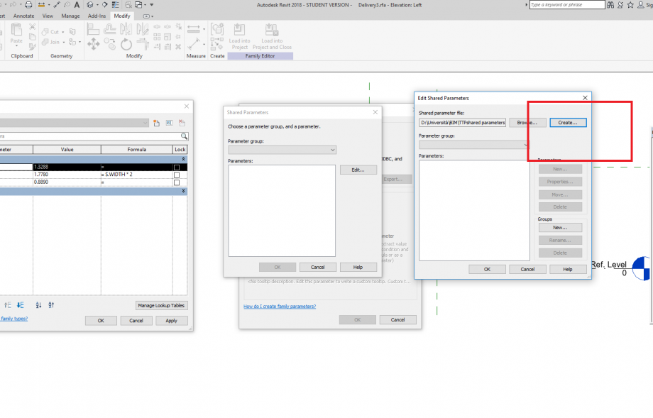

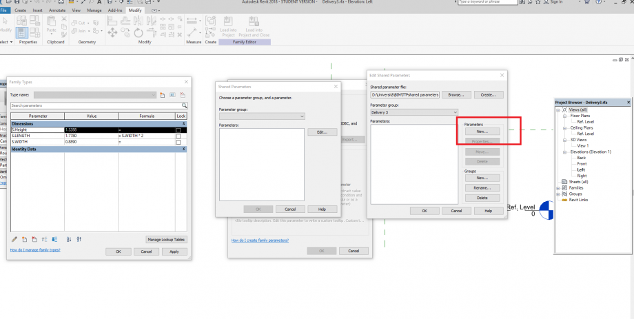
 I do the same for alle the parameters and reload the family into projcet
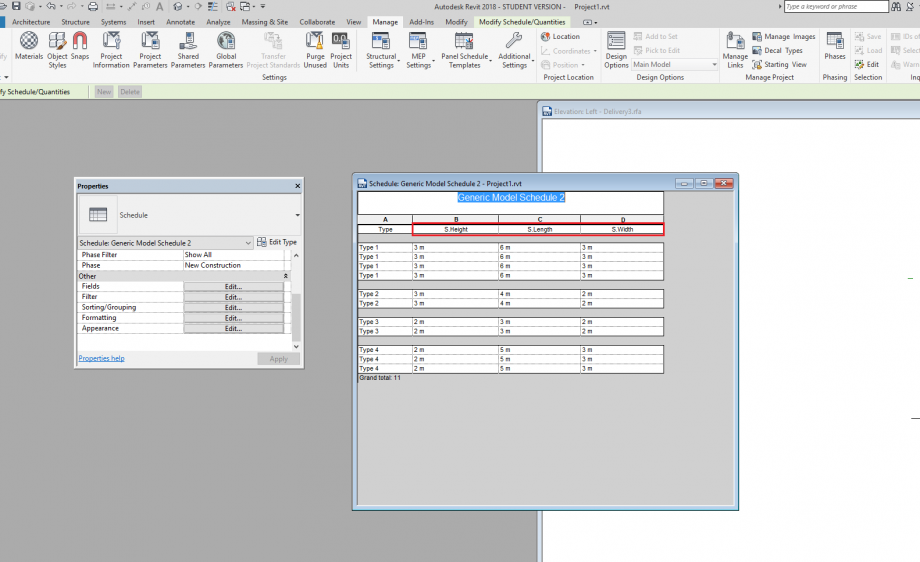
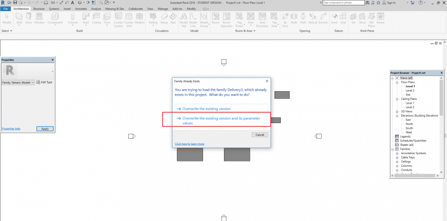 Now i can find my parameters in the schedule.
and i'ts over.
Thanks!
Ven, 04/05/2018 - 11:39
 Jlaria.Volpi
Ven, 04/05/2018 - 10:43
Jlaria.Volpi
Ven, 04/05/2018 - 10:43
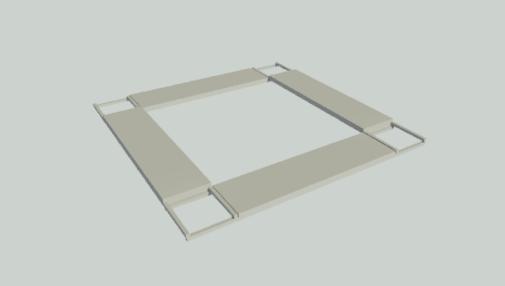
La quarta consegna è improntata sulla "Tettonica digitale", andremo a creare un oggetto che si attacca su una superfice e che quindi, vuole essere agganciato. Creeremo così, una dima (famiglia madre) a cui agganceremo un oggetto (famiglia figlio).
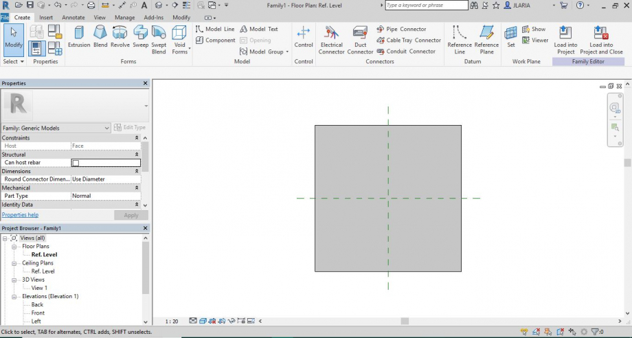
Per prima cosa creiamo il file famiglia children:
-New family --> Generic Model face based
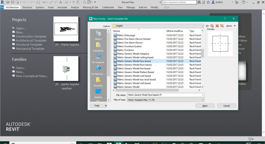
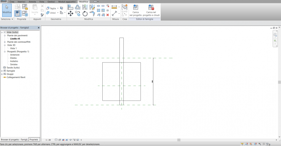
si apre un file in cui troviamo un piano di base che sarà il piano di appoggio della madre in cui andrò a posizionare l'oggetto figlio e a cui posso modificare le dimensioni a mio piacimento.
 -vado nella vista in pianta e creo i piani di riferimento e faccio un estrusione che andrò ad allineare ai piani.
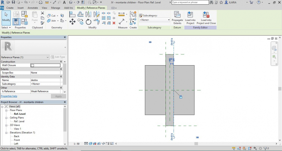 Ora ho un piano di riferimento "front back" e uno "left right" che chiamerò "lato destro" e creo un ulteriore piano opposto che chiamerò "lato sinistro"
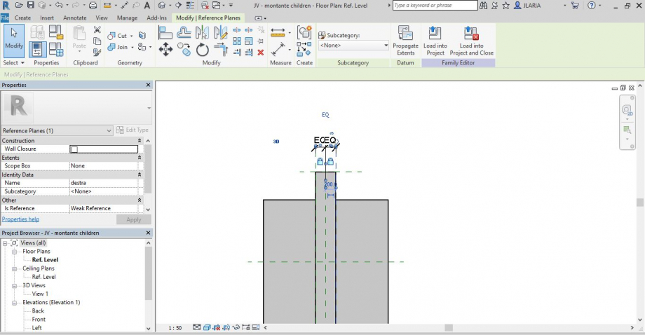
voglio che questi due piani siano simmetrici rispetto al piano di riferimento centrale e allora quando vado a creare le quote, ne creo una doppia (faccio due click e poi la posiziono) e mi compare il vincolo equalit (EQ) in alto, che indica che le due distanze devono essere uguali :
Annotate --> quote --> dimension
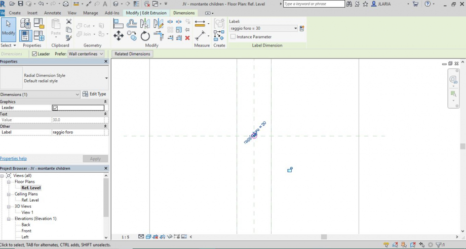
si crea così un oggetto che andrà ad agganciarsi al piano nel punto di intersezione dei due assi fissi e qui vadi a creare il punto di inserimento. In qesto punto andiamo a creare il Foro:
faccio un estrusione circolare nel punto di intersezione dei miei due piani di riferimento e prima di chiudere l'estrusione, clicco sulla quota temporanea e stabilisco una dimensione delraggio di questa circonferenza e al di sotto di questa clicco sull'icona della quota,
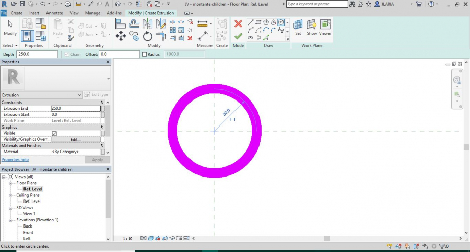
così trasformo questa in un parametro permanente e lo chiamo "raggio foro".
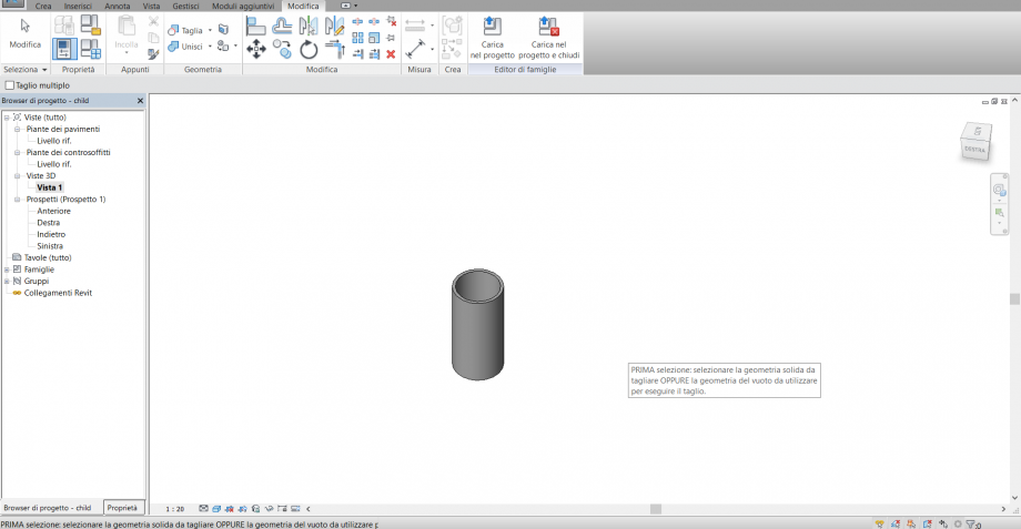
 Così ho creato un estrusione e ne posso modificare le lunghezze. ma questa è ancora un estrusione e non un foro
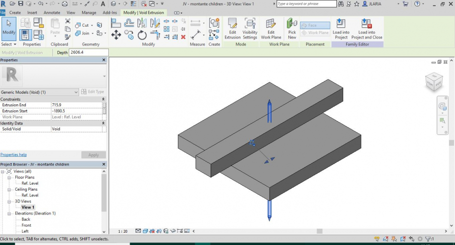 allora vado a trasformarlo in foro:
seleziono l'estrusione --> properties -->solid/void --> seleziono void
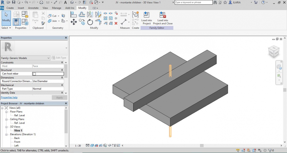 posso anche selezionare Cut e così lo taglia dall'oggetto base
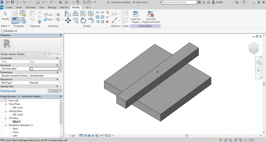 vado nei parametri e creo "diametro" e collego questo parametro al foro:
family tipes -->formula impongo che il raggio sia la metà del diametro
creo anche un parametro di larghezza dell'oggetto e sempre dalla formula lo collego al dimametro dando una formula a quest'ultimo che dipende dalla dimensione della larghezza.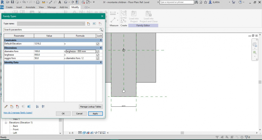 ora vado a creare le altre quote a mio piacimento per modificare e organizzare al meglio il mio oggetto figlio
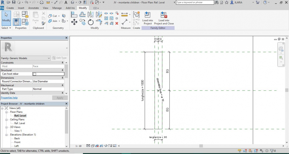 salvo il file figlio JV - montante children e vado a creare l'oggetto famiglia madre:
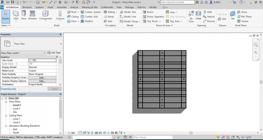
creo un modello famiglia generico e qui andrò ad inserire i miei piani di appoggio.
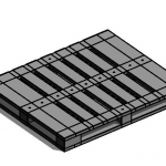
Voglio creare un pallet allora creo i piani di riferimento necessari e le varie quote, ora creo le estrusioni (la mia dima)
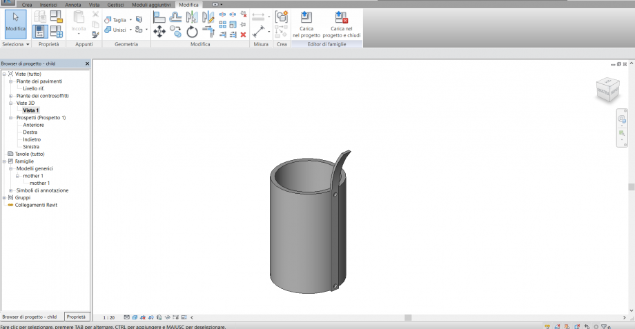
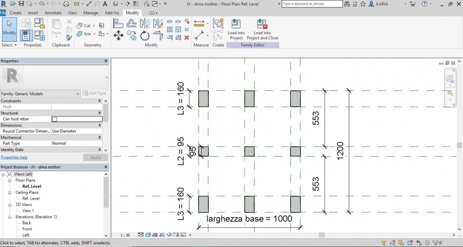 salvo il file : JV - montante mother e su questo vado ad importare il mio oggetto children che comparirà solo nei punti in cui avrà una superficie su cui agganciarsi (altrimenti il programma mi darà errore) e così creo la composizione.
 Se voglio vedere l'asse del foro graficamente:
torno nella famiglia children: --> properti --> progeat browser --> metto la vista di prospetto --> Annotate --> simbolic lyne: così creo una linea di progettoche sarà visibile solo nella vista di pianta e che mi servirà per allineare il centro dell'oggetto nel piano di riferimento da me voluto nell'oggetto madre.
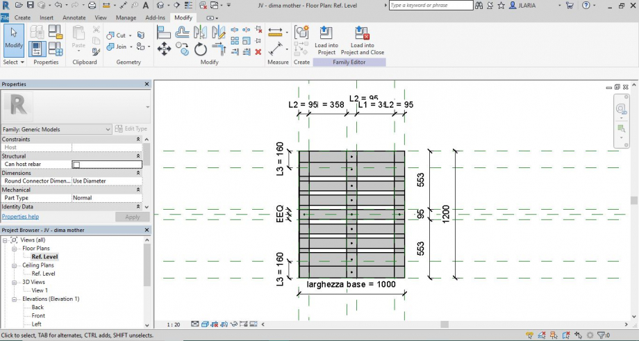
carico nuovamente il figlio nella madre e salvo.
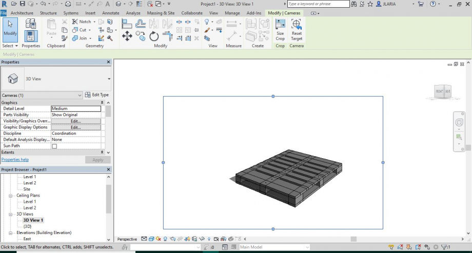
creo un nuovo file che chiamo JV - assemblaggio pallet in cui vado ad inserire il mio oggetto (madre), composto da dei file children agganciati e assembliati al file madre.
da qui creo le viste dell'assemblaggio
 Lorenzo Di Biase
Ven, 04/05/2018 - 10:07
Lorenzo Di Biase
Ven, 04/05/2018 - 10:07
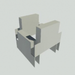
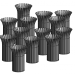
Creazione di una composizione tettonica mediante l'assemblaggio di più elementi.
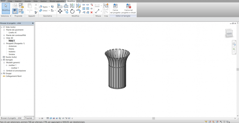
Ho creato un file families metric generic model based on face, all'interno del quale ho creato la mia asta ricurva.
Successivamente su un file families metric generic model sono andato a modellare la base cilindrica che sosterrà gli elementi ricurvi.
Ho importato in mother il file child e creato la composizione andando a connettere le aste lungo il perimetro del cilindro.
Infine, ho caricato il blocco in project e creato una composizione di più elementi.