


 Antonio Vellucci
Mar, 25/11/2014 - 12:30
Antonio Vellucci
Mar, 25/11/2014 - 12:30
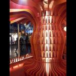
Ciao a tutti, ieri presso la stazione termini mi sono imbattuto in questa installazione! Mettendo da parte il linguaggio architettonico che richiama le forme del prodotto sponsorizzato, si vede bene come l'oggetto sia costituito da componenti parametrici che variando generano una seduta, dei scompartimenti per i prodotti e un controsoffitto. QUESTO OGGETTO E' IDENTICO AI LAVORI CHE AVETE FATTO TUTTI VOI!! Se vi capita vi consiglio di andarlo a vedere e vi renderete conto che la parametrizzazione ci circonda in modi più o meno espliciti, ma soprattutto che quando parametrizzate dovete avere sempre bene a mente i vincoli di fattibilità dettati ad esempio dalla tecnologia che scegliete o dai costi di produzione ed altro.
Buon proseguimento!
Mar, 25/11/2014 - 12:57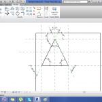 Thyago alves
Mar, 25/11/2014 - 11:37
Thyago alves
Mar, 25/11/2014 - 11:37
Mi scusi , ma come faccio a parametrizzare un triangolo equilatero con i piani parallelli o dimensioni di angoli ?
Mar, 25/11/2014 - 11:39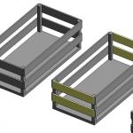 julia medrado
Lun, 24/11/2014 - 20:21
julia medrado
Lun, 24/11/2014 - 20:21
In questo post applicherei i concceti della seconda consegna. Devo continuare a lavorare sulla scatola.
Prima vi ricordo che la scatola ci sono i lati, dei pezzi in cui sono collegati i lati e un pezzo base nello stesso piano del pavimento. Per ogni pezzo ho lavorato su archivio "face base" ognuno con questi nomi:
- JEM - base;
- JEM - haste;
- JEM - laterale;
- JEM - laterale 2. (ad esempio)
Ho applicato i primi concceti per disegnare (creare i piani di riferimento, fare la estrusione, collegare ogni lato al piano di riferimento, assegnare i parametri di riferimento altezza, lunghezza e larghezza), ma anche ho attribuito il parametro di materiale.
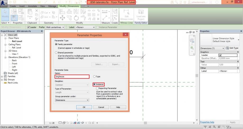
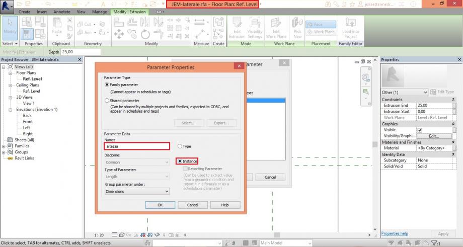
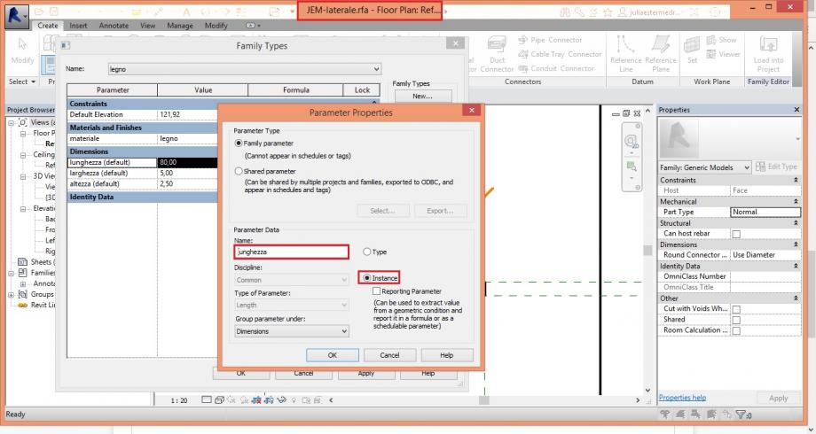
In questo parametro ho scelto la opzione "type" e ho creato due tipi di materiale (legno e metallo) cambiando le proprietà di colore e modello.
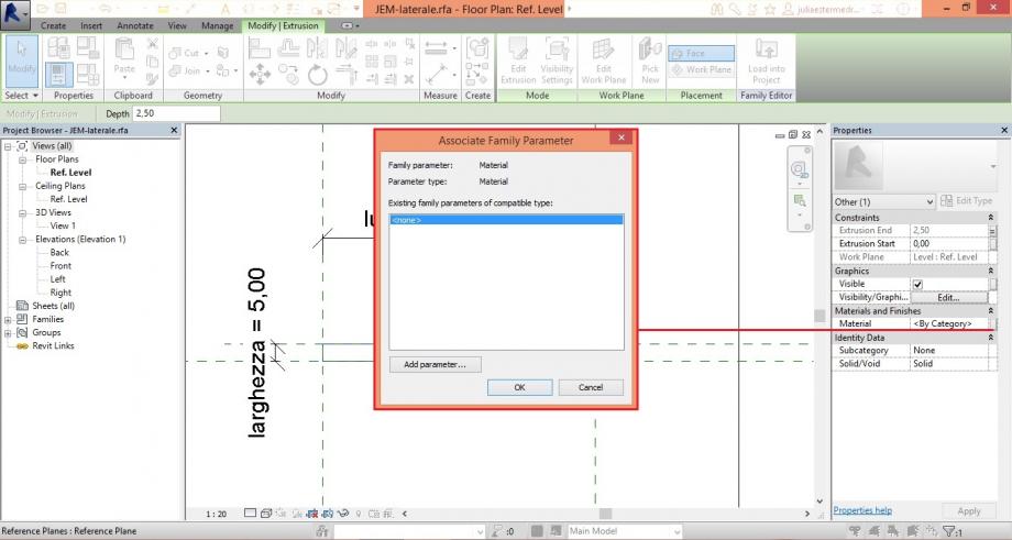
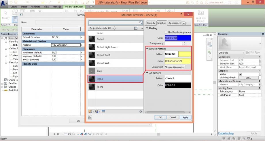
Dopo ho associato ogni materiale con una nuova famiglia tipo (family types) corrispondente.
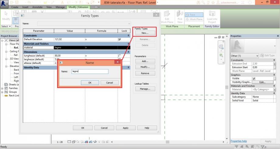
Questa operazione ho fatto per tutti i 4 archivii JEM - (base, lateral 2, lateral, haste).
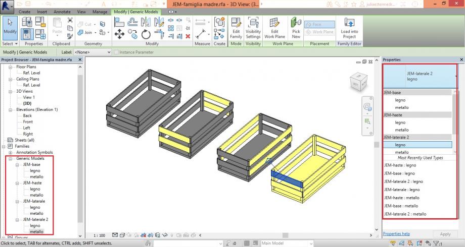
Ormai, per montare la scatola ho lavorato nell'archivio Famiglia Madre che aveva l'estensione in "Generic Model".
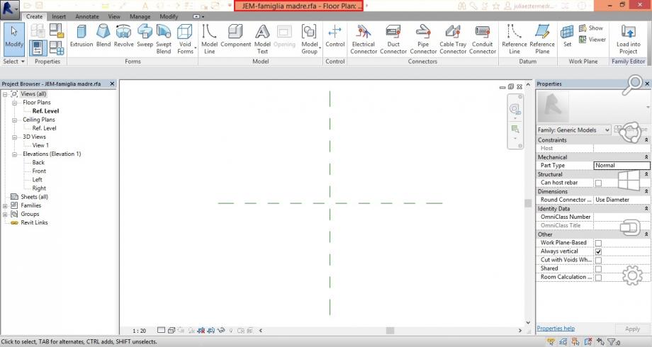
Dopo ho scaricato in progetto, su archivio famiglia madre, ongi pezzo.
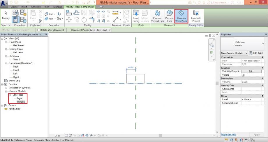
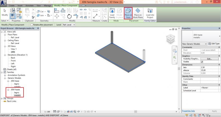
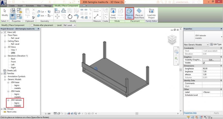
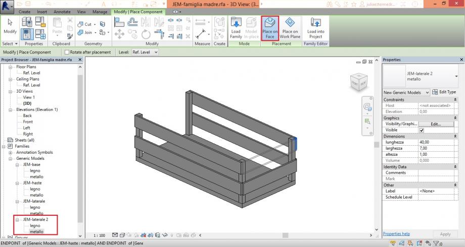
Dopo di finirla ho cambiato i materiali.
 andrea piattella
Lun, 24/11/2014 - 16:02
andrea piattella
Lun, 24/11/2014 - 16:02
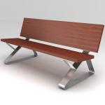
I have create with Revit the bench designed in the picture above. First of all i studied the pieces that compose it, two hiron structure that are the base of the bench, the overstructure in wood and the bolts that hold the all. I created one family for each piece [ FILE-NEW-FAMILY-METRIC GENERIC MODEL FACE BASE ]. I decide the face view according to the function tha the object will have.
First of all I put the correct project units [ MANAGE-PROJECT UNITS ] and according to the dimention of the piece i put the project units. For example for the bolts I used millimeters meanwhile for the wood sticks I used meters.
Than I draw the REFERENCE PLANE to define the borders of my object. I used the coomand ALIGNED DIMENSION To mesure and set the lenght between the planes.
After I set the referenc plane I added the parameter using the command FAMILY TAPES. I created a list of parameters than I assigned each parameter a dimension.

I essagned the parameter cliking on the dimension and choose the correct one.

After delimitated all the dimension and the thicknesses of the piece I extruded the surface [ CREATE-EXTRUSION ]. I changed view and i used the front view to adjusted the lenght of the ectrusion creating another reference planeI.

I did the same passages for the other parts (wood sticks and bolts)
But I used a different command to create the bolts holes. I used the command VOID EXTRUSION drawing a circle on the hiron structure.


Finished each family( for each part) I created the mother family in order to combine all the components. I used the command [ INSERT- LOAD FAMILY (I searched the family that i want to import ). Than CREATE-PLACE COMPONENT (and i select the reference surface). To place the component in the correct position i uesd the command MOVE.


Lun, 24/11/2014 - 17:43
 Matteo Molinari
Lun, 24/11/2014 - 16:02
Matteo Molinari
Lun, 24/11/2014 - 16:02
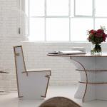
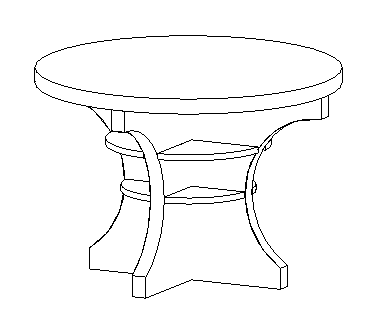
I decided to design the table shown in the headline picture. It's a table built in cardboard's pieces assembled interlocking.
I created a folder on my desktop in order to have all the pieces of my table in one place.
I started to design the table opening a new family, this family will be my "Tavolo - famiglia madre" (table - mother family). This is the main file where i'll be assembling all the pieces of the object. I opened the new family, and choose GENERIC METRIC MODEL.
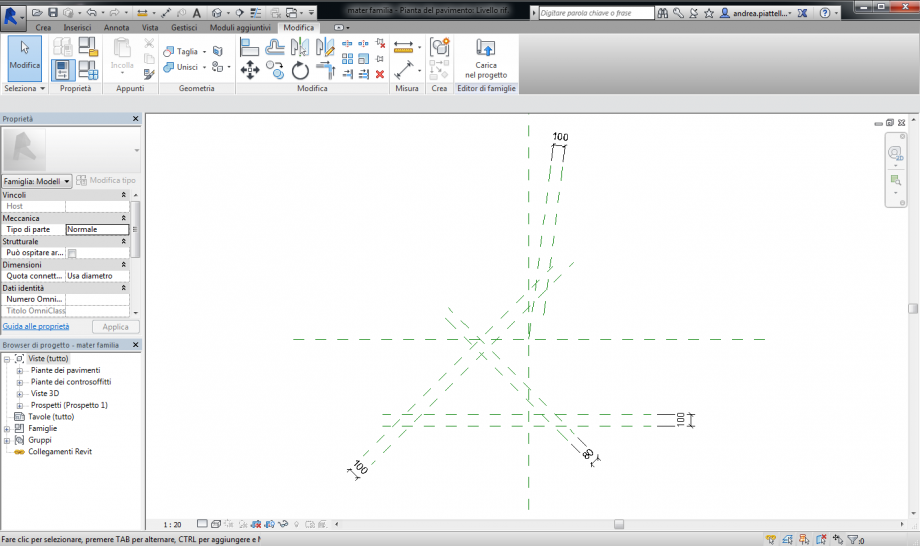
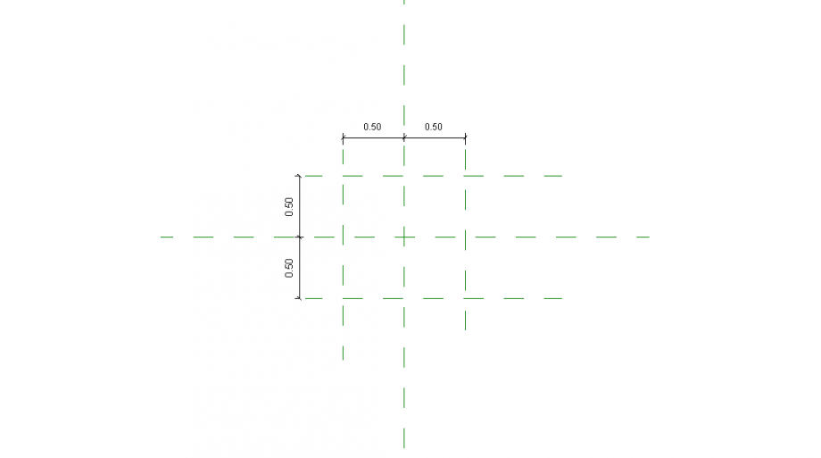
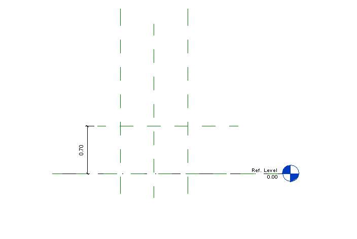
First of all I changed the units of the file in in meters. It's important to set the dimension of the object parametrically. In order to do so I used the command REFERENCE PLANE, (p.1) and locked the dimension. I did so in the plant and front view. (p.1 p.2)
 p.1
p.1
 p.2
p.2
After I set theReference pPlane I added the parameter using the command FAMILY TYPES. (p.3) With this command I was able to create parameter to assign to each dimension. When I create the parameters e.g. lunghezza, profondità their value was 0.00 that's because they weren't assigned to any object. After they were assigned to an object the value changed (p.4)
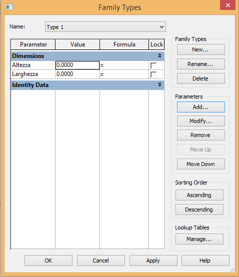 p.3
p.3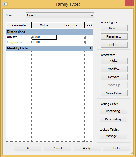 p.4
p.4
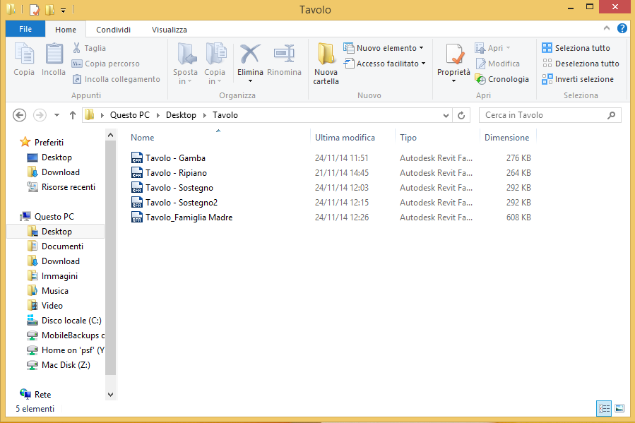
After this I saved my document in the folder "Table". Every object in the folder will be named "Tavolo - x" in order to have everything organized and the metadata well defined.
Now I have to design the pieces of the table. The mother family is composed by four sub-family: Tavolo - Gamba, Tavolo - Ripiano, Tavolo - Sostegno e Tavolo - Sostegno2. (p.5)
I'll explain the constroctruction of only one of this pieces (Tavolo - Ripiano) since the modus operandi is always the same.
I used the command OPEN, NEW FAMILY, GENERIC METRIC MODEL. As for the mother family I set the main dimension with the command REFERENCE PLANE and add a parameter to each dimension. I used the command CREATE, EXTRUSION and draw a circle. The ray of the circle is locked to the reference plane so that when the parameter of the reference plane changes the lenght of the ray changes as well. (p.6) I did so also for the thickness of the shelf. (p.7)
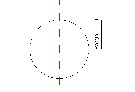 p.6
p.6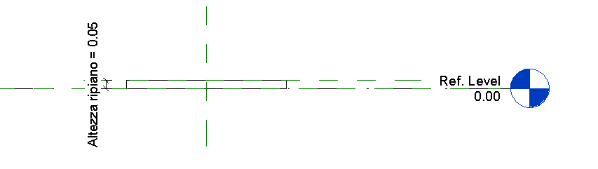 p.7
p.7
After this my drawing of this part is complete. (p.8)
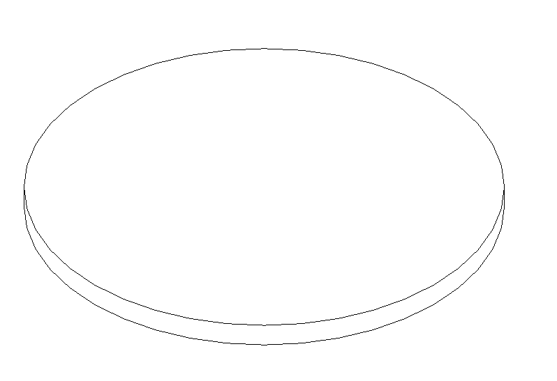 p.8
p.8
The other parts are: Tavolo - Gamba (p.9), Tavolo - Sostegno (p.10) e Tavolo - Sostegno2
 p.9
p.9 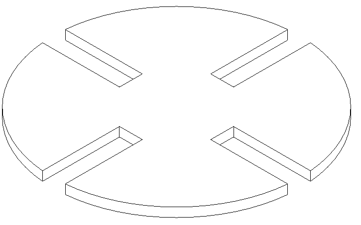 p.10
p.10
It's important to say that in order to design the joints of the legs and the crutch (p9, p.10) I used the command VOID EXTRUSION. This allowed me to subtract matter to the main object and create a void.
After this I opened again my mother family in order to combined all the pieces of the table. The shelf is glued to the legs of the tabels. The legs are held togheter by the crutch that are interlocked. I used the command LOAD FAMILY and then PLACE COMPONENT in order to virtually build the table.
I loaded the family "Tavolo - Gamba" four times. and then put it all togheter. (p.11,p.12,p.13)
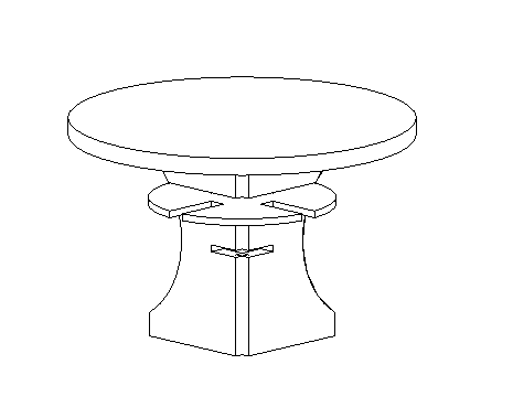 p.11
p.11
 p.12
p.12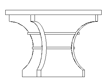 p.13
p.13