


 Matteo Molinari
Ven, 28/11/2014 - 15:46
Matteo Molinari
Ven, 28/11/2014 - 15:46
With this object I added the use of metric generic model faced based family and parameters.
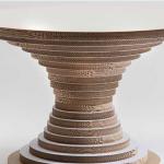
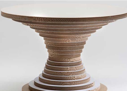
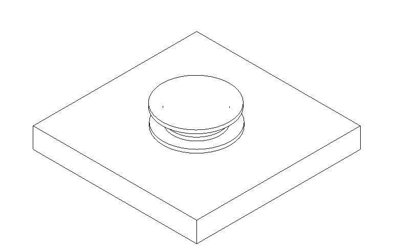
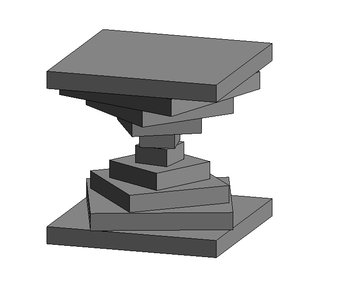
I kept the theme of a cardboard made object, this time designing in revit a coffe table. The original design was for a table, I adapted it to my needs. (p.1)
 (p.1)
(p.1)
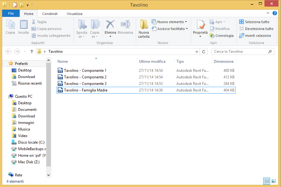
This table is formed by three sub-family, that i reapet two times. So the families are: Tavolino - Famiglia Madre, Tavolino - Componente 1, Tavolino - Componente 2, Tavolino - Componente 3
As I did for the previous design I created a folder named "tavolino" in which I placed the mother family and the sub families (p.2)
 (p.2)
(p.2)
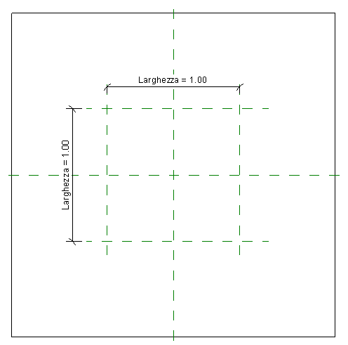
I created the mother family with a GENERIC METRIC MODEL FACED BASED, in which through the REFERENCE PLANE I gave the main dimension of the coffe table. Hight and width (p.3 p.4)
 p.3
p.3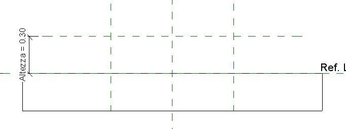 p.4
p.4
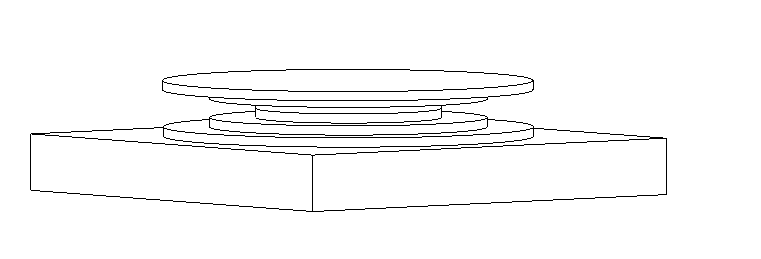
Then I created the sub-families as for the mother family I used a GENERIC METRIC MODEL FACEB BASED of the component of the table. I used the command EXTRUSION. Each component is a cilinder with a different ray in order to give movement to the design. It's important to notice that with this kind of family when is imported in the mother family you have to place it on a surface, the surface where is placed influences the way the object can be moved in the mother family. This time I added a parameter to the ray of the circled, I called it RAGGIO to keep it simple. Following the three components with each parameter (p.5,p.6,p.7)
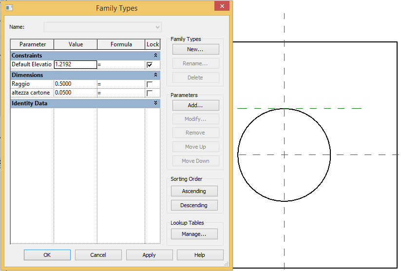 p.5
p.5
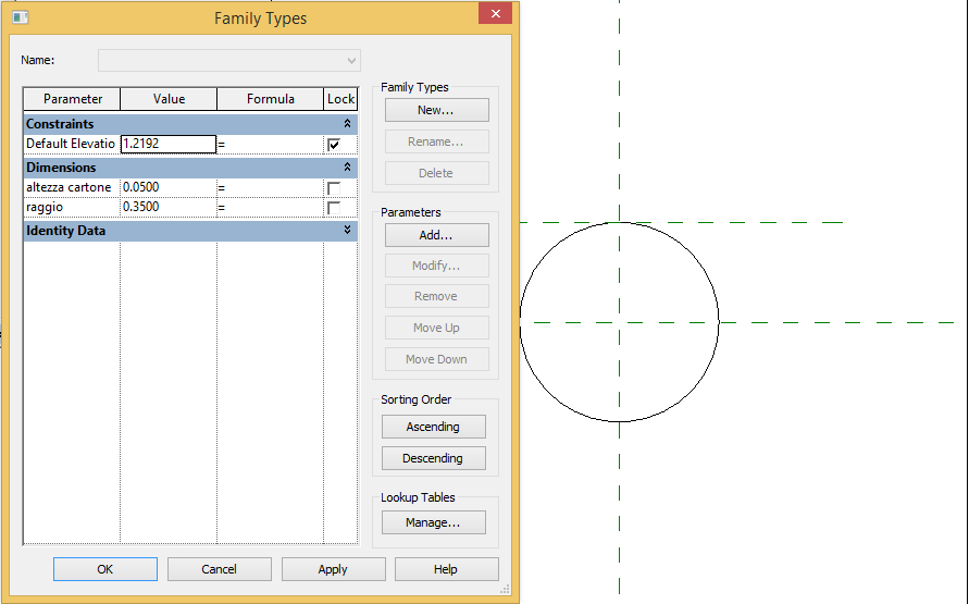 p.6
p.6
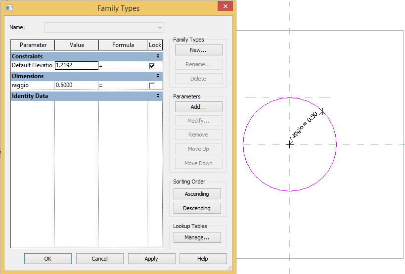 p.7
p.7
Now after I have finished with the components of the table and added a parameter to each one of them it's time to put it in the mother family.
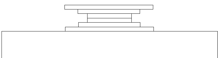
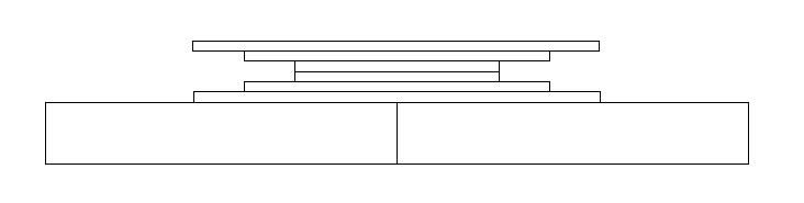
In order to place it in the correct way I started from the bottom up. I used a REFERENCE PLANE and the command ALIGN in order to have all the centers of the extruded cilinder bloked in one place. (p.8,p.9)
 p.8
p.8
 p.9
p.9
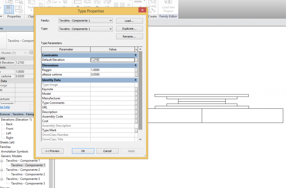
This coffe table has maximum diameter of 1 meter, now using the parameters I can create a coffe table of every dimension I want. For example I can have a maxium diameter of 2 meter and consquently the other 2 components will have a bigger diameter. To change the parameter I can simply double click on the family in the left side menu and a window with all the parameter will show up. (p.10)
 p.10
p.10
Now I do the same things with the other two components and I have a different dimension coffe table but with the same design of the previous one. This was possible because I used the parameters. (p.11,p.12)
 p.11
p.11
 p.12
p.12
 Vitor Carnevale
Gio, 27/11/2014 - 11:40
Vitor Carnevale
Gio, 27/11/2014 - 11:40
Ciao a tutti,
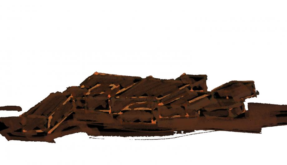
Questa é la continuazione della Panchina fatta dalla consegna 1. mi dispiace il ritardo per questa seconda consegna.. non sono stato nella ultima lezione e no abbia visto su sito sulla seconda consegna. Ho pensato di fare un video invece una serie de immagini, mi sembra più didatico e con più transparenza ( è facile vedere tutti i miei sbagli di questa forma).
Segue il link del video
https://www.youtube.com/watch?v=zTJrQYxLB9I&feature=youtu.be
non ho saputo mettere il video in questo spazio. Spero que aveva funzionato.
un dubbio che ho avuto in questa lezione è di come fare parametri angolare perché volevo fare una inclinazione del appoggiatoio e non sono riuscito purtroppo
e nel video come possono notare, non sono riuscito a funzionare il "family type" del sopporto panchina. non lo so il perchè.
e più una volta mi dispiace per il mio italiano. Spero che stiano capendo.
A presto,
Gio, 27/11/2014 - 11:52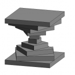 luisapegorini
Mer, 26/11/2014 - 23:24
luisapegorini
Mer, 26/11/2014 - 23:24
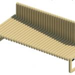
L'idea è di creare una panca con un solo tipo di pezzo, ma che varia le sue dimensioni ed angoli, per creare strozzature e torsione. L'idea originale era meglio, ma non ho potuto lavorare nel modo che desideravo in Revit, quindi ho semplificato l'oggetto.
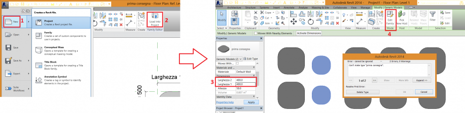
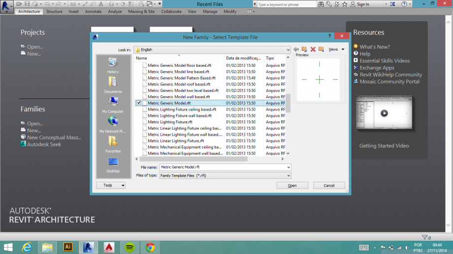
1) Quando aprire il Revit, selezionare New Family. Aprire il file "Metric Generic Model".
2) Create > Solid Extrusion. Scegliere lo strumento Rectangle e disegnare un quadrato di qualsiasi dimensioni.
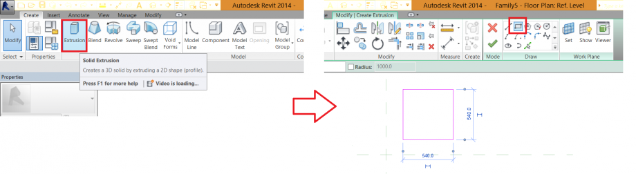
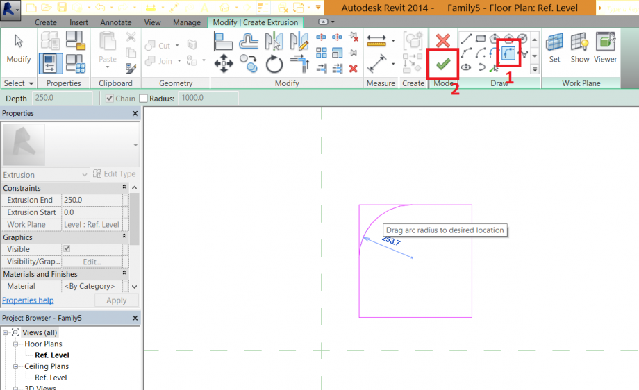
3) Scegliere lo strumento Fillet Arc. Applicare lo stesso angolo sui quattro lati. La forma è pronta, premere su Finish Edit Mode.
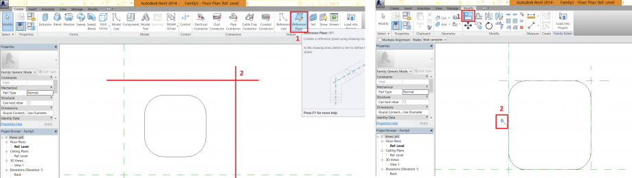
4) Create > Reference Plane. Disegnare due linee. Una verticale e l'altra orizontale. Dopo scegliere lo strumento Align, selezionare il piano di riferimento in seguito la linea parallela, chiudere il lucchetto. Ripetere sui quattro lati.
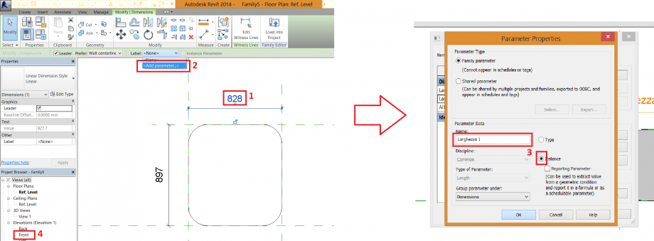
5) Cliccando su due piani di riferimento, dopo sulla dimensione mostrata. Label > Add parameter...
Si apre la finestra Parameter Properties, scegliere un nome per il nuovo parametro, marcare l'opzione Instance. Ripetere la stessa cosa sull'altra dimensione. Dopo, scegliere Elevations > Front, e creare un Reference Plane e Parameter per l'altezza del oggetto.
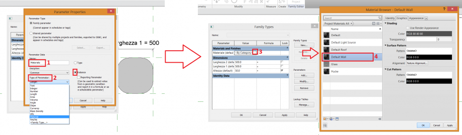
6) Creare nuovo parameter per il materiale (Add...). Scrivere un nome, cambiare Type of Parameter per "Material" e scegliere l'opzione Instance. Dopo cliccare nell'angolo nella fase 3 e la finestra de materiale si apre. Scegliere quale vi piace.
7) New > Project. Cariccare la famiglia nel proggeto e fare la quantità de copie che vuoi. Editare il parameter (3), ma a questo punto c'era un errore, non è possibile cambiare più la dimensione. Ho dovuto cliccare su Edit Family per cambiare la forma, cancellando le curve per fare un quadrato.
Dopo cliccare di nuovo su Load into Project > Overwrite the existing version.
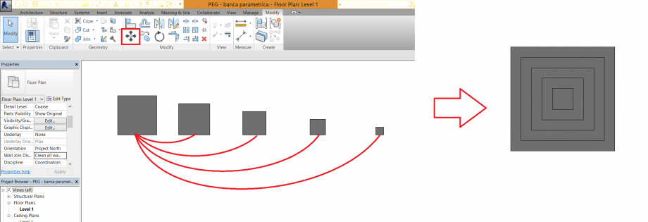
8) Fare cinque copie. Cambiate i parametri seguendo la regola: 500 > 400 > 300 > 200 >100. Con lo strumento Move, muovere tutti i quadrati come l'immagine.
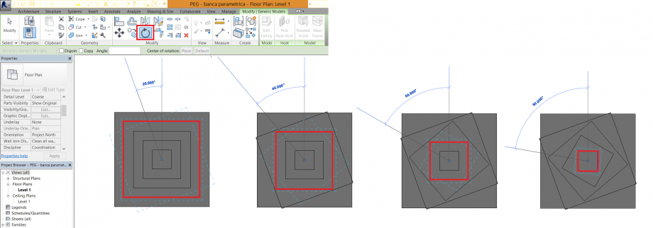
9) Selezionare lo strumento Rotate per girare dal maggiore quadrato al minore, seguendo la regola: 20° > 40° > 60° > 80°
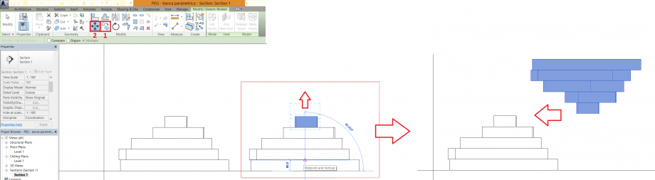
Creare una Section (1), selezionare View > Sections > Section 1. I quadrati ancora facciono sovrapposizione. Selezionare Move (3) per muovere i quadrati su.
10) Con lo strumento Copy, fare una coppia dell'oggetto. Dopo dovete muovere pezzo a pezzo su, perchè non ho potuto ruotare nel senso verticale nel Revit. Quindi dovete aderire i due pezzi, creando l'oggetto finale.
Gio, 27/11/2014 - 02:56
 josecarrari
Gio, 27/11/2014 - 00:23
josecarrari
Gio, 27/11/2014 - 00:23
Per creare una panca parametrica ho fatto un sketch con diverse variazione mentre l'altezza, lunghezza e profondità.
Da questa idea la construitabilità è fatta a partire di un quadrato parametrizato dove si puó controlare differente formazione nella composizione della panca.
1. Crea una nuova famiglia in "Families > New > Metric Generic Model"
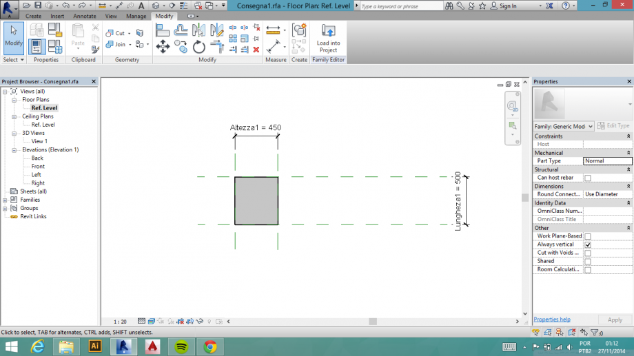
2. Inseria i plani di riferimenti e colleghi con ogni lato del quadrato.
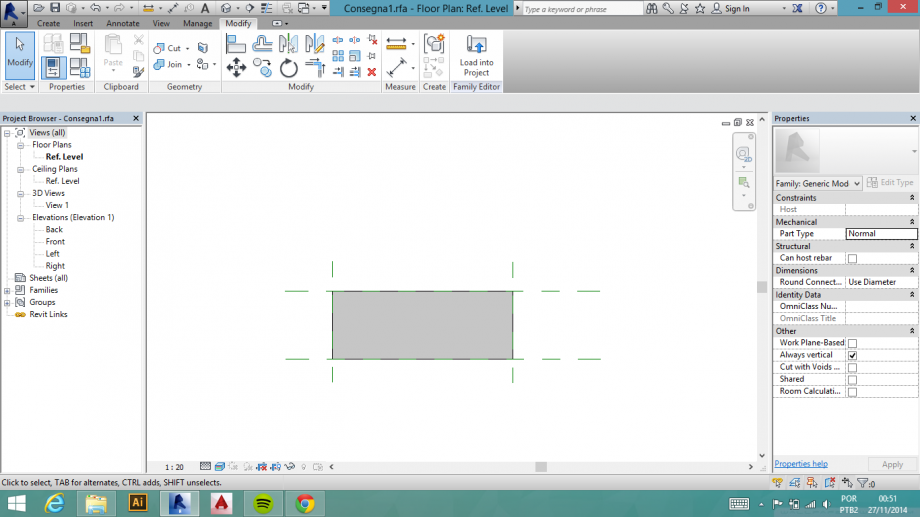
3. Agiunggere le misure su tutte le face dove si mettera dopo le parametre della panca, o sia, altezza, lunghezza e profondità.

4. Dopo aver messo queste informazione deve agiunggere i parametri a loro. In questo caso i parametri sono pre determinatti a tre variazione delle dimensione (altezze 1, 2 e 3 - lunghezza 1, 2 e 3 e profondità 1, 2 e 3).
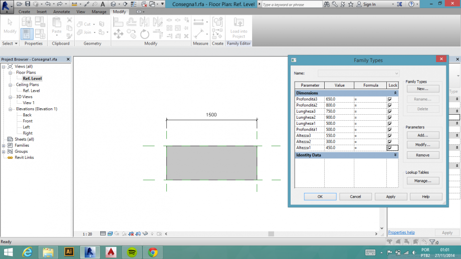
5. Adesso si fa una assossiacione tra mesure e parametri, per fare con che le dimenzione delle bloche della panca sia la stessa dello specifico parametro.
6. Applica il materiale nella estrusione che diventerà la panca.
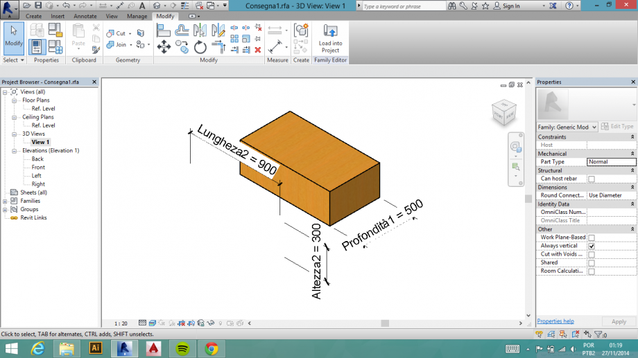
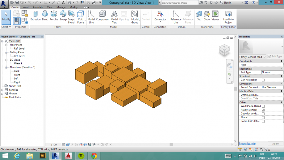
7. Si multiplica il bloco e i dispostanno mettendo le diverse parametre nelle misure, cosi si trova lo effeto variabile del progetto.
 Rodrigo Reis
Mer, 26/11/2014 - 07:02
Rodrigo Reis
Mer, 26/11/2014 - 07:02
How can i insert a reference to rotate this object?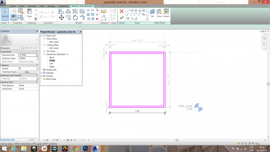
Sto provando a fare una sequenza con lo stesso oggetto, però, ogni oggeto con una rotazione diversa...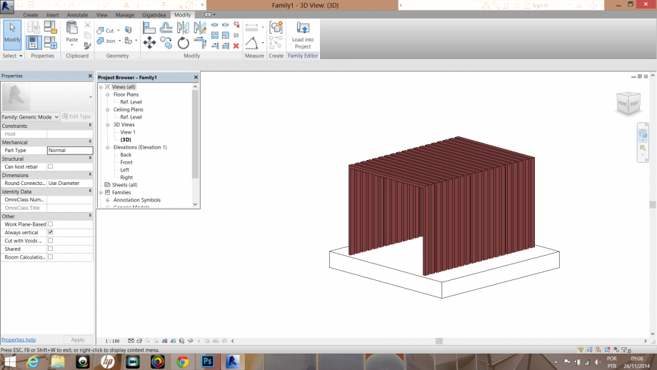
Ho provato criare due nuove plani di referimento... 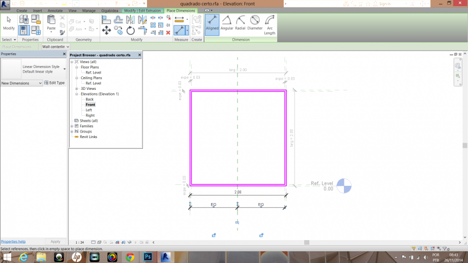
Cosí.. e criare una quota (parameter) angolar.
Ma non sono risciuto, per niente, a ruotare...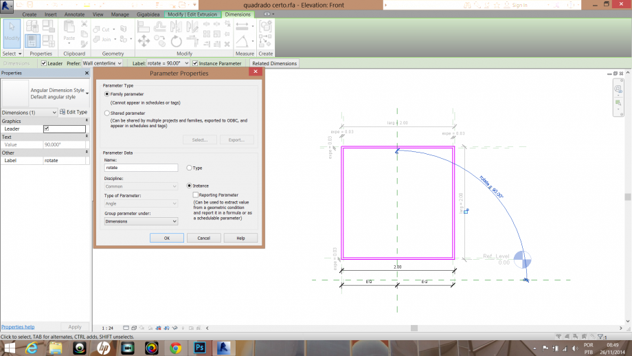
Qualcuno puòi aiutarmi, per favore?
Mer, 26/11/2014 - 09:30