


 Paula Soldi
Gio, 04/12/2014 - 10:51
Paula Soldi
Gio, 04/12/2014 - 10:51
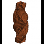
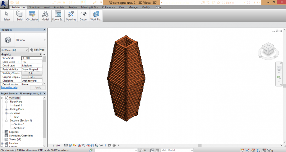
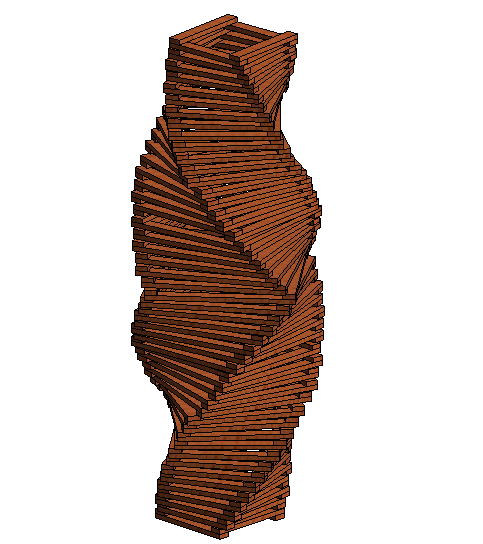
Io ho creato questa luminaire da un oggetto. Con più tre oggetti, ho creato la forma di base per tutta la luminaire, cosi è stato possibille l'effetto della luce che passa per tra i oggetti.Vi spiegherò meglio:
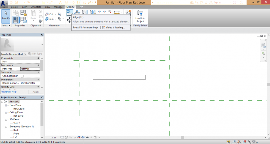
Prima de tutto, ho aperto il Revit con new family: Metric Generic Model. Dopo, ho disegnato un rettangolo con lo strumento Rectangle che si trova a Create- Extrusion. Per altre due parti che non hanno un piano di riferimento, bisogna creare un Reference Plane. Dopo di questo, ho allineato tutti i piani di riferimento con l'oggetto perchè cosi si può quotare.
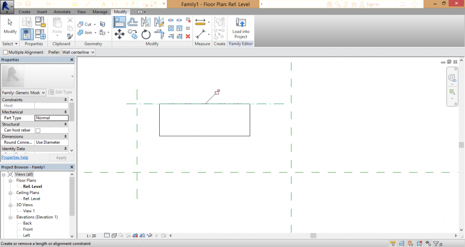
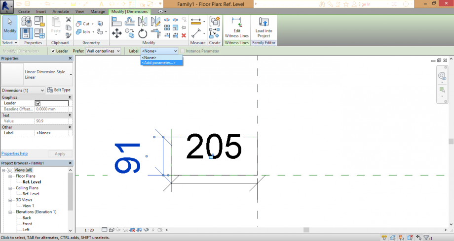
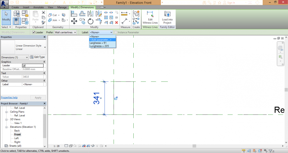
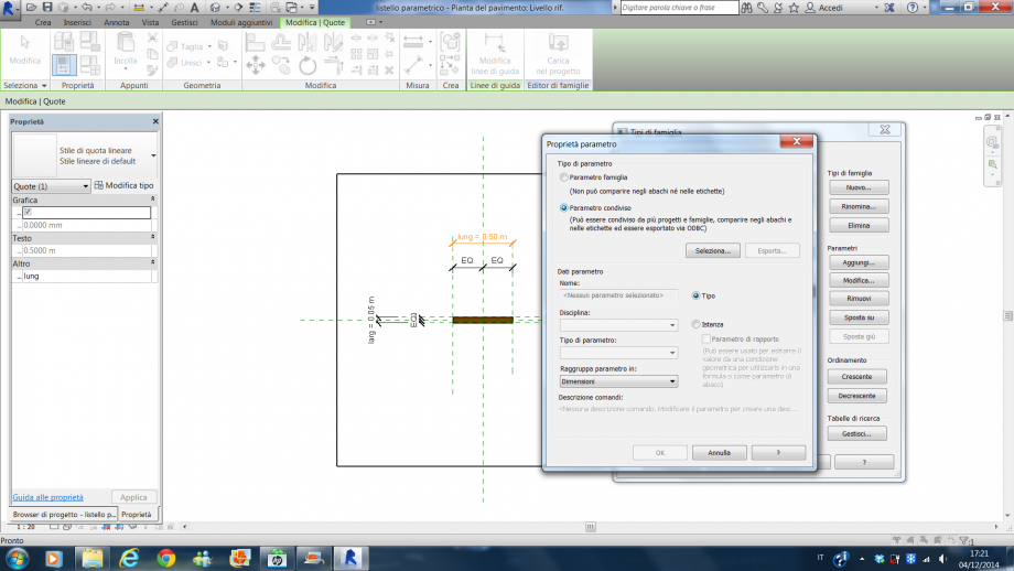
Seleziona una quota, va a Label per aggiungere un parametro a questa quota come Larguezza. Con altra quota si può creare il parametro de Lunghezza. Però il parametro di Altezza solo si trova nella vista frontale. Ho ripetuto, creando un altro piano di riferimento, allineando con la quota e cosi creando il parametro di Altezza.
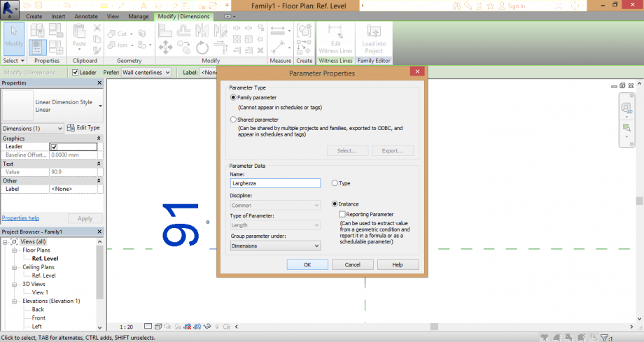
Dopo di questo, apro Family Type per mettere i dimensioni certo di tutti i parametri, anche creare un nuovo parametro di materiale. Per questo seleziona ADD, e nell tipo di parametro deve scegliere il tipo Materiale.

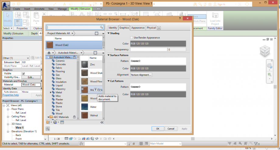
Per cambiare il tipo di materiale, seleziona l'oggetto e nelle caratteristiche dell'oggetto c'è Materiale. Cosi si può scegliere quale materiale te piace, a me, di legno perchè questa Luminaire è stato fatta con piccole pezzi di legno.
Fatto questo, la prima parte della consegna è finita. Cosi ho aperto un nuovo Project nella opcione Metric. Con i tasti WT si può guardare tutte le finestre aperte. Selezionando l'oggetto e con un click in Load to Project si mette l'oggetto nell suo nuovo progetto.
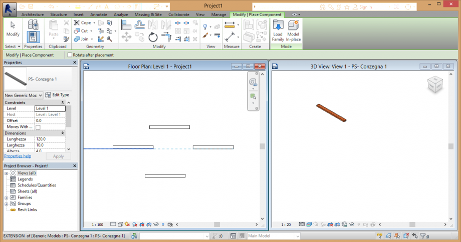
Faccio il download dell progetto quattro volte, per formare un'altro oggetto che due pezzi supportano altre due pezzi, e è questa forma di base che faccio la luminaire. Per questo devo ruotare due pezzi.
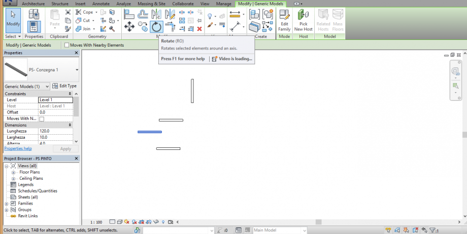
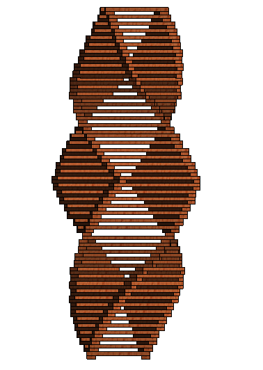
Copio e incollo la forma di base quante volte è necessario. Però, in ogni forma di base devo diminuire la dimensione di ogni pezzo: prima 0.4 cm, dopo 0.8 cm e cosi via. Posso montare lo scheletro della luminaire, ripetendo la stessa dimensione due volte.
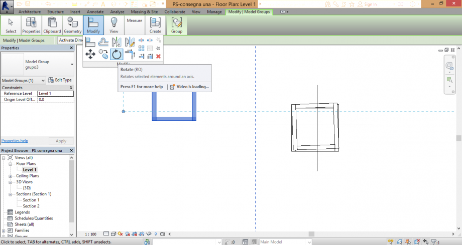
Per avere la rotazione nell suo corpo, prima di montare lo scheletro della luminaire, bisogna creare un gruppo per ogni forma di base. Con la forma di base selezionada clicco in Create Group.
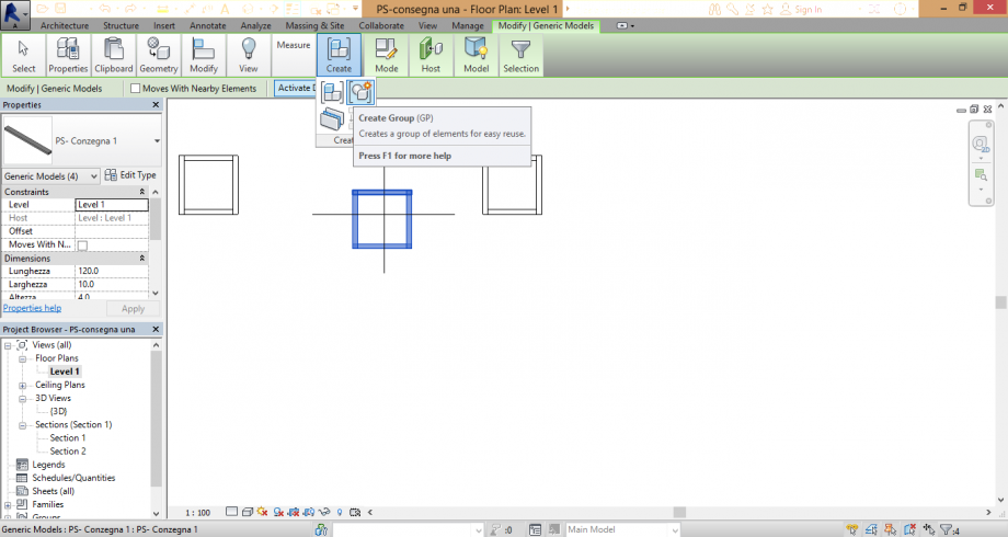
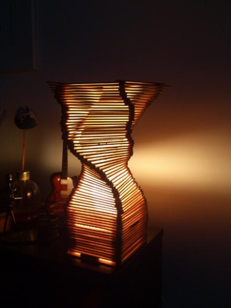
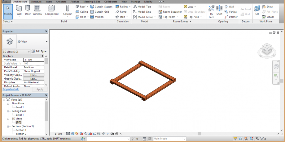
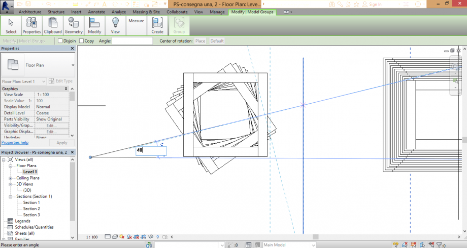
Cosi, posso ruotare ogni forma di base separadamente. Prima con 5 gradi, dopo 10 gradi e cosi via. Per rimanere in questa posizione finale, bisogna movere una forma di base, dopo la prossima, dopo la prossima...
Ed è pronto:
Gio, 04/12/2014 - 20:25
 Daniele.tricarico
Gio, 04/12/2014 - 19:28
Daniele.tricarico
Gio, 04/12/2014 - 19:28
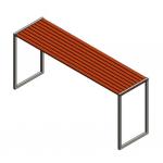
Per questa consegna ho aggiornato uno dei modelli che avevo realizzato per la prima consegna ovvero il tavolo.
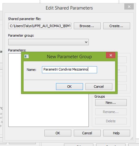
Come prima cosa ho creato una cartella in cui contenere i parametri condivisi che gestiscono i singoli elementi che compongono l’oggetto d’arredo.(3.1)
3.1
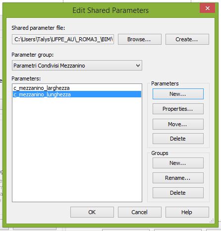
Quindi ho creato dei parametri condivisi per il listello in legno in cui ho compreso anche quello del materiale. (3.2)(3.3)

3.2

3.3
In fine ho salvato la famiglia dei listelli in quella degli arredi. (3.4)

3.4
Ho seguito gli stessi passaggi per la creazione del telaio, che fa gamba al tavolo, salvando i suoi parametri nella cartella di parametri condivisi che avevo realizzato in precedenza.(3.5)(3.6)

3.5

3.6
Per creare l’abaco degli elementi che compongono il mio tavolo, ho aperto un nuovo progetto.(3.7)

3.7
Dopo aver assemblato il tavolo ho per creare l’abaco ho cliccato su “vista”, poi su “abaco”.(3.8)

3.8
Ho selezionato la famiglia a cui appartengono gli elementi che compongono il tavolo ed in seguito ho evidenziato le voci che mi interessava comparissero nell’abaco.(3.9)

3.9
Quindi ho ottenuto l’abaco in cui sono comparsi tutti gli elementi che costituiscono il mobile, le loro quantità e dimensioni.(3.10)

3.10

3.11
Gio, 04/12/2014 - 19:38
 StefanoConverso
Gio, 04/12/2014 - 16:49
StefanoConverso
Gio, 04/12/2014 - 16:49
La lezione ha introdotto il tema che verrà trattato nel tema d'esame,
vale a dire il "passaggio di scala" dalla componentistica all'architettura.
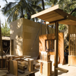
I progetti mostrati sono di Carlo Scarpa e di Studio Mumbai.
Ecco il link alla lezione, da Google Presentations:
https://docs.google.com/presentation/d/1wIOn99elqUZMJyZbJihTa5mvyMBYzsJQ...
Ecco il video della lezione pratica, che ha avuto come tema i Revit curtain wall panels,
purtroppo è mancata la registrazione audio:
 Talys Medeiros
Gio, 04/12/2014 - 14:46
Talys Medeiros
Gio, 04/12/2014 - 14:46
Ho aggiornato il mio progetto della struttura in acciaio (link della seconda consegna http://bim.rootiers.it/node/172), utilizzando le stesse famiglie "figlie" face based generic model (trave e pilastro), che sono state aggiornate nei commenti della seconda consegna. Ho creato diversi tipi nelle famiglie "figlie", con lo scopo di rendere possibile la scelta del profilo mettalico adeguato alla impostazione strutturale.
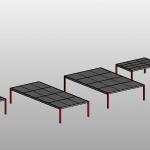
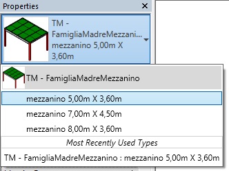
In questa consegna, ho caricato le famiglie "figlie" (con le sue variazioni) nella famiglia "madre" generic model per comporre diversi tipi di mezzanini, cioè, tipi di famiglie "madre" che possono essere caricate sul progetto.
Ho caricato tre tipi di trave, secondo i profili metallici che avevo criato nella famiglia "figlia".
FAMIGLIA MADRE - PARAMETRI CONDIVISI
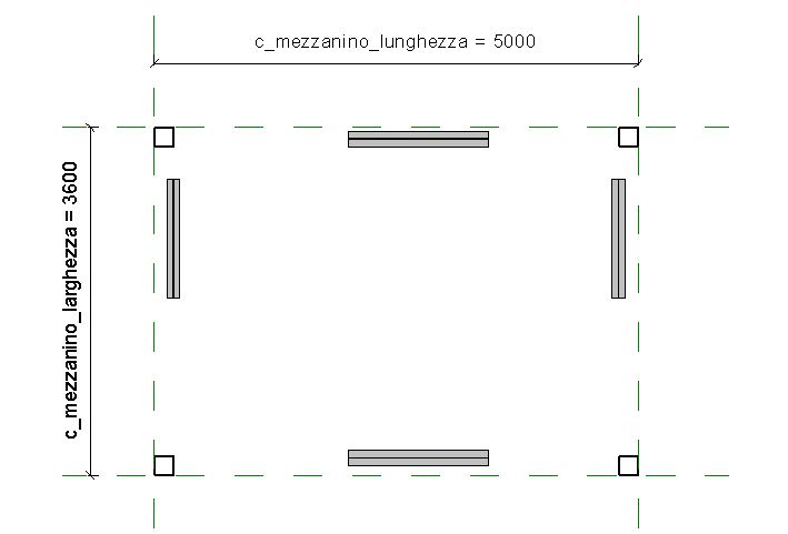
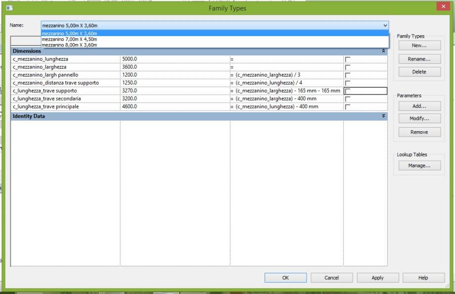
Ho creato i parametri condivisi necessari per regolare la famiglia madre e creare diversi tipi.
I parametri convidisi relativi alla larghezza e alla lunghezza totale del mezzanino:
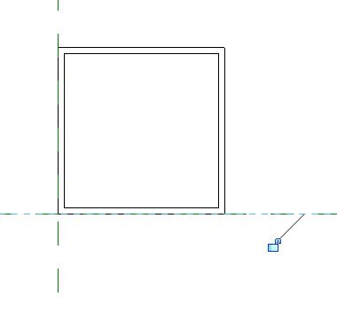
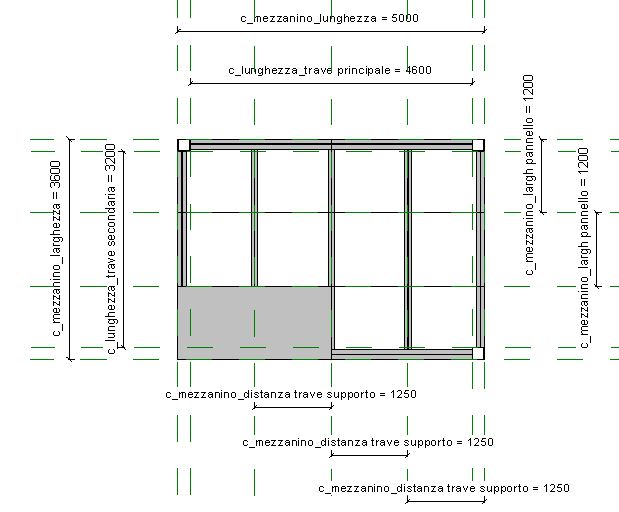
Ho collegato i pilastri ai piani di riferimenti della larghezza e lunghezza totale:
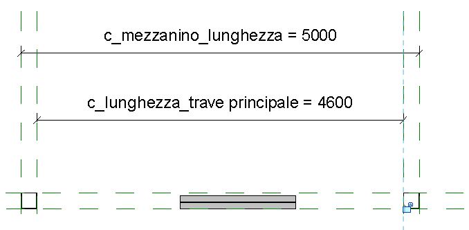
Dopo aver collegato i pilastri, ho connettato le travi agli assi:
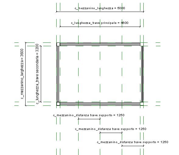
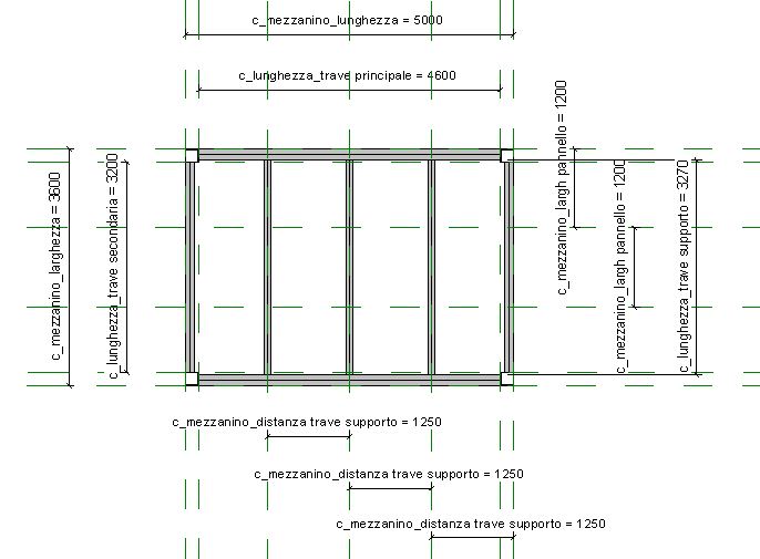
Ho creato i piani di riferimenti relativi alle travi che appoggiano i panelli per il pavimento e ho collegato le travi:
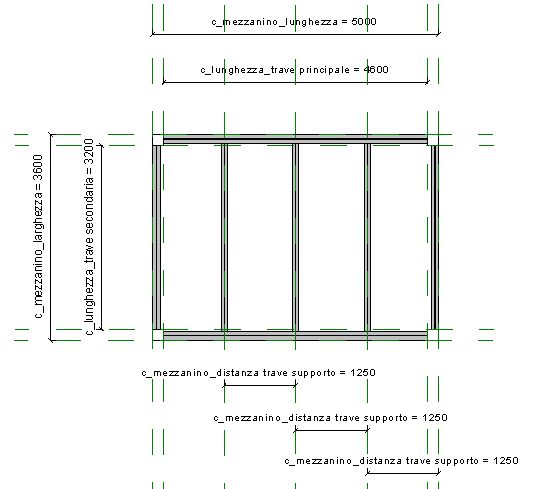
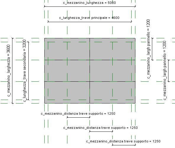
Ho creato i piani di riferimenti relativi agli panelli per il pavimento. Ho creato una estrusione e l'ho collegata con questi piani:
Ho fatto altri parametri relativi alle lunghezze delle travi (lunghezza trave principale, lunghezza trave secondaria e lunghezza trave supporto), che sono stati utilizzati per comporre le schedule:
PROGETTO MEZZANINO - SCHEDULES
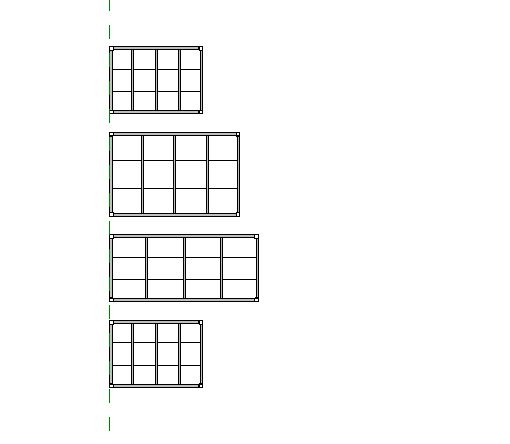
Dopo aver creato tre tipi di famiglie "madre", le ho caricate sul progetto del mezzanino:
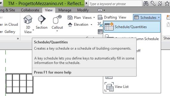
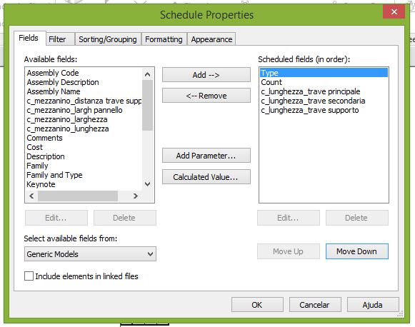
Ho creato una nuova schedule:
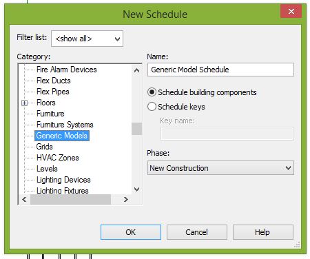
Ho cliccato su generic models e ho selezionato le informazioni che devono comporre la schedule:
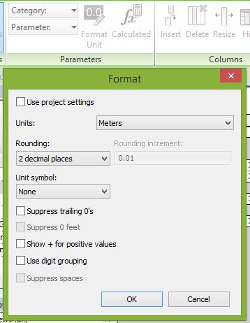
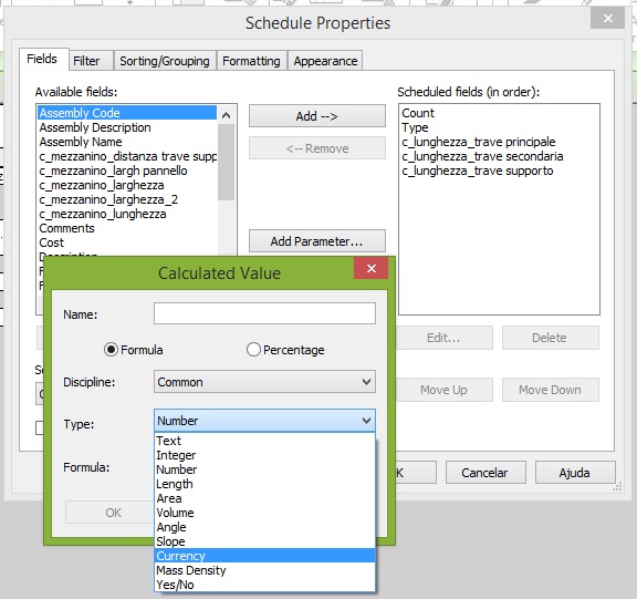
Ho cambiato la unità:
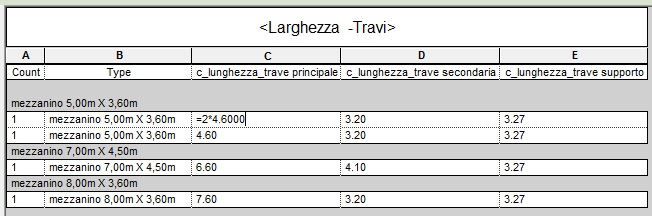
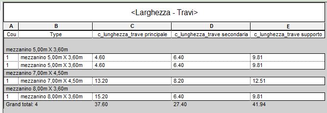
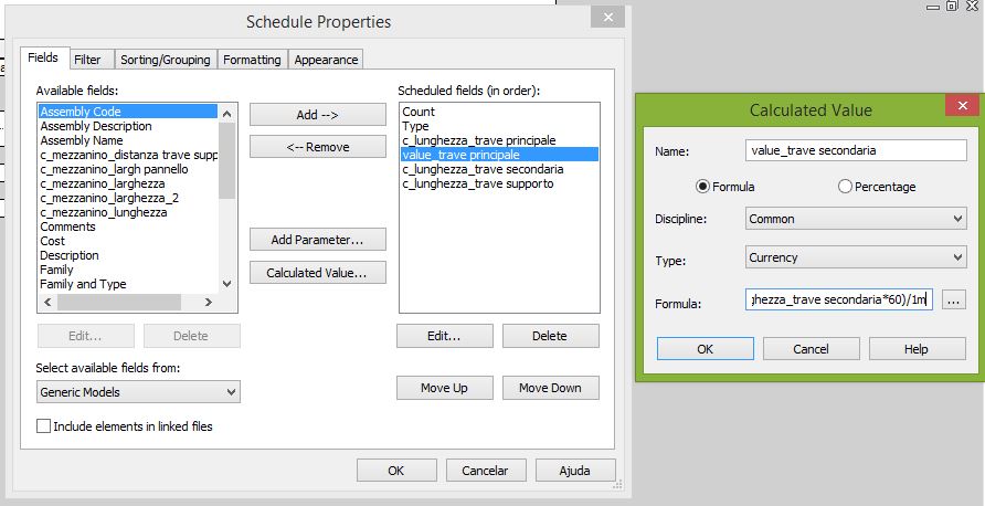
Ho moltiplicato la lunghezza delle travi per la sua quantità (ci sono due travi principali, due travi secondarie e tre travi di supporto) e ho messo il suo totale:
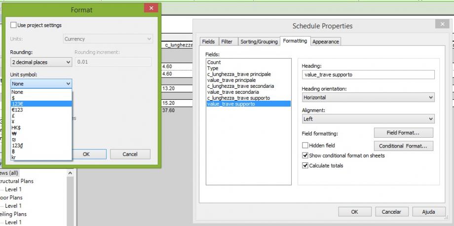
Ho aggiunto il costo per ogni tipo di trave:
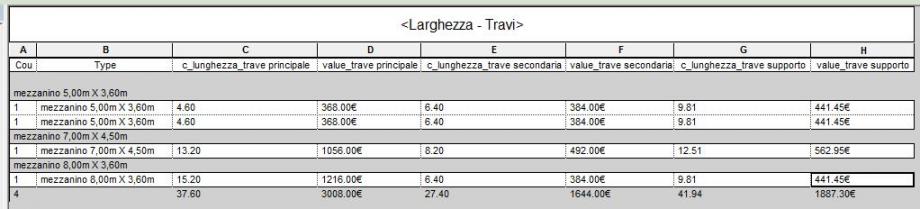
Ecco la schedule con i costi relativi ad ogni tipo di trave:
Gio, 04/12/2014 - 15:47
 Klemen Stegu
Gio, 04/12/2014 - 12:34
Klemen Stegu
Gio, 04/12/2014 - 12:34
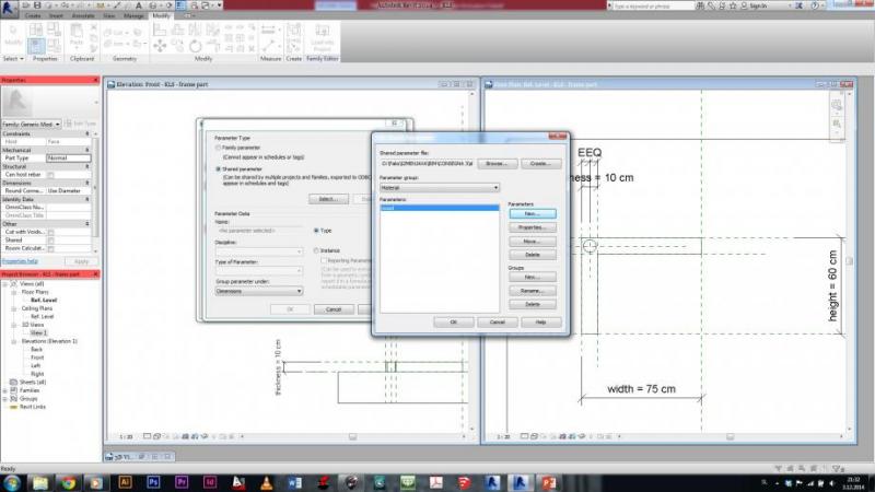
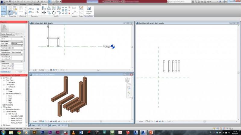
For this third consegna i tried to do a simple bench from similar parts. The idea was that I create wooden profiles and connect them with steel pole.
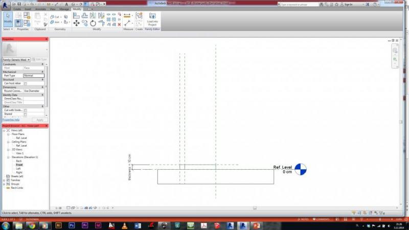
1. I created profile with extrusion - all asigned parameters are Type parameters, except for height parameter, which is an instance parameter, so I am able to generate different profiles:
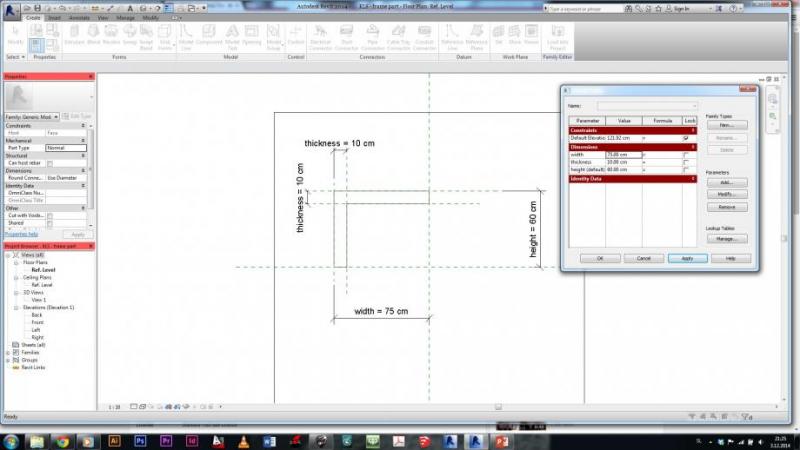
2. Also the thickness of the profile was asigned as a Type parameter:
3. I created now holes inside my profile - at both starts of the profile and in the middle, so I am able to rotate and connect the profiles in different positions. And with all that, I created different Types of my profile:
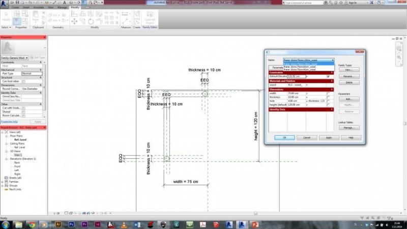
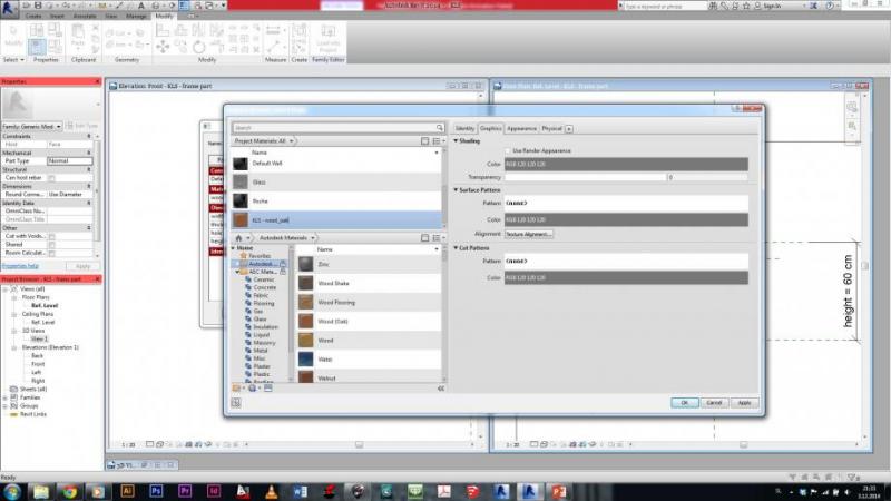
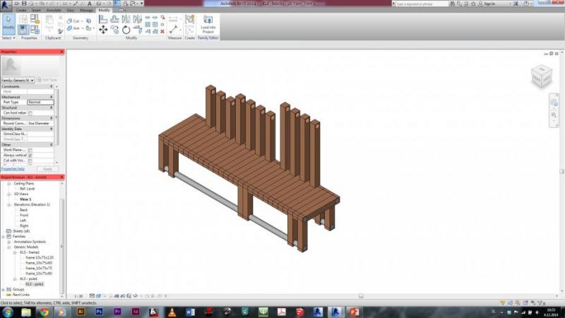
4. Lastly I asigned my profile a material - wood_oak. This parameter is shared paramater:
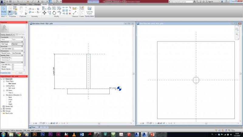
5. I also created a pole family, which will connect my profiles:
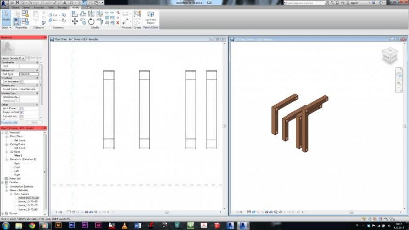
6. With all that, I imported all the things into main family, turning the profiles as i wanted them to be and constructing a model of the bench:
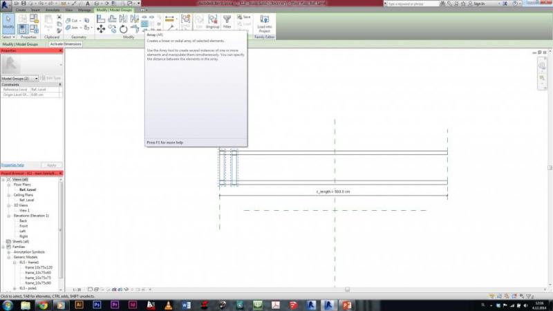
7. But when it comes to creating schedule for my model, I didn't know how to do it... So i decided, I will create another bench, which would be more simple, by using just the pole and one of my profiles, which will be rotaded differently, to give the bench the stability. To create that, i used array tool:
8. And now, with setting my familys to shared, i was able to create this simple schedule:
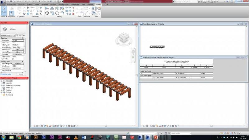
But somehow, I cannot change the length of my bench. The length is set as Type parameter, so I cannot put more benches into project and change each one of them. But I also cannot change the parameter to instance, because it is used in a formula for another parameter. Any soultions?
Gio, 04/12/2014 - 12:54