 eri.agnelli
Mar, 09/12/2014 - 18:52
eri.agnelli
Mar, 09/12/2014 - 18:52
Questa settimana ci viene chiesto di studiare l’ambito dei curtain wall e di provare quindi a gestire la modellazione di una facciata in cui un componente “pannello” viene assemblato (o montato, per usare un termine “tettonico”) su di una griglia, che può essere intesa sia come generatrice geometrica astratta dell’insieme, sia come effettiva griglia di montanti a sorreggere tali pannelli.
La facciata che andrò a modellare può essere pensata sia come una doppia pelle che vada a sovrapporsi ad un “pan de verre” con la funzione di schermatura, che come una vera e propria facciata in cui le aste e i pannelli rappresentano rispettivamente telai delle finestre e pareti opache.
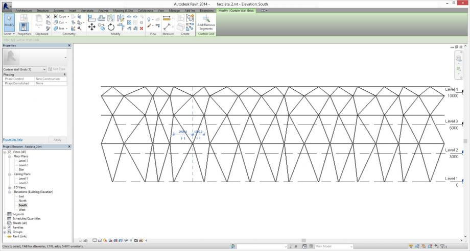
Per la concezione della parete sono ricorsa ad una matrice triangolare, usando quindi la diagonale del modulo della griglia.
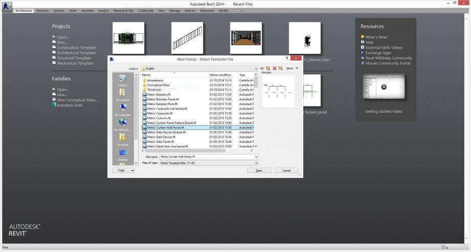
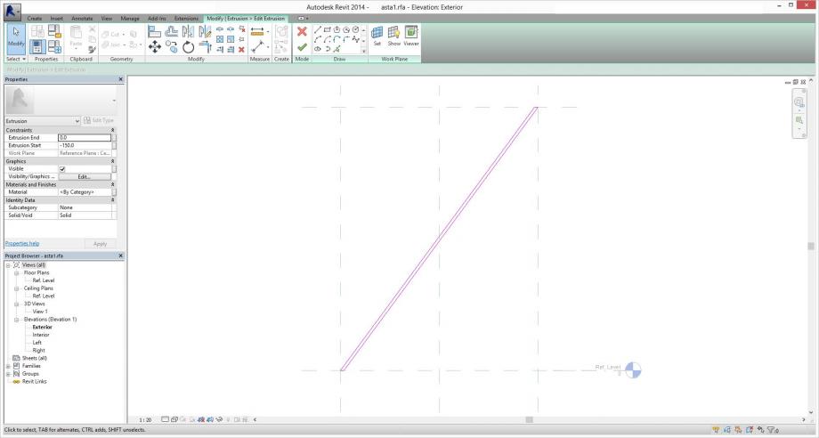
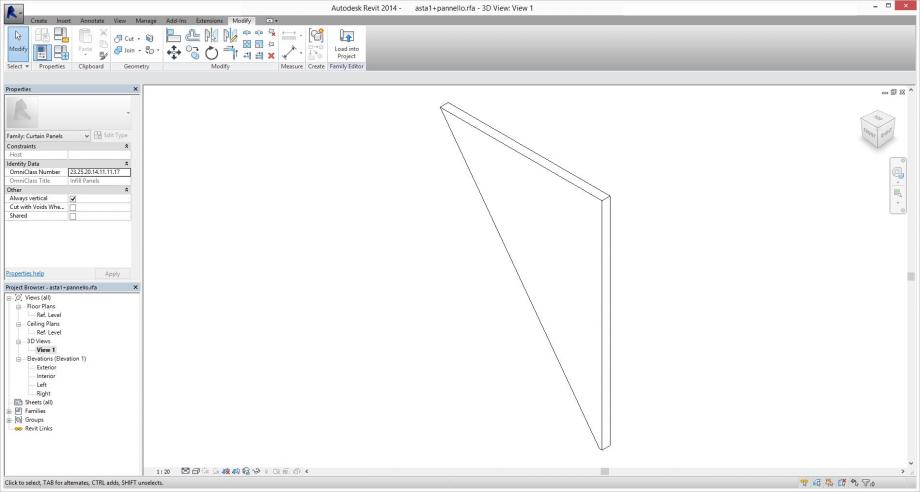
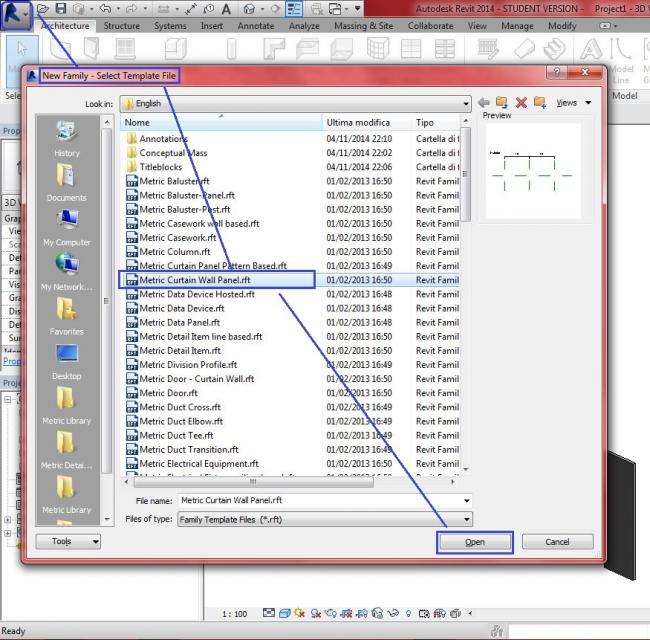
La modellazione della famiglia del pannello deve avvalersi del template “metric curtain panel”
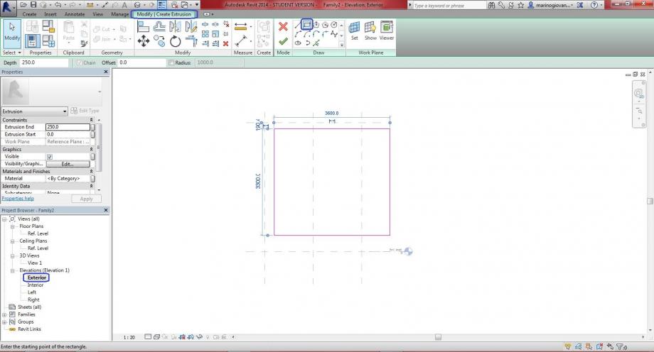
Dalla vista in prospetto frontale modello con il comando “create – extrusion” una semplice asta inclinata che occupi proprio la diagonale del modulo. Vado quindi a vincolare i punti degli spigoli esterni agli assi di riferimento verticali e la base e la sommità dell’asta ai piani di riferimento orizzontali.
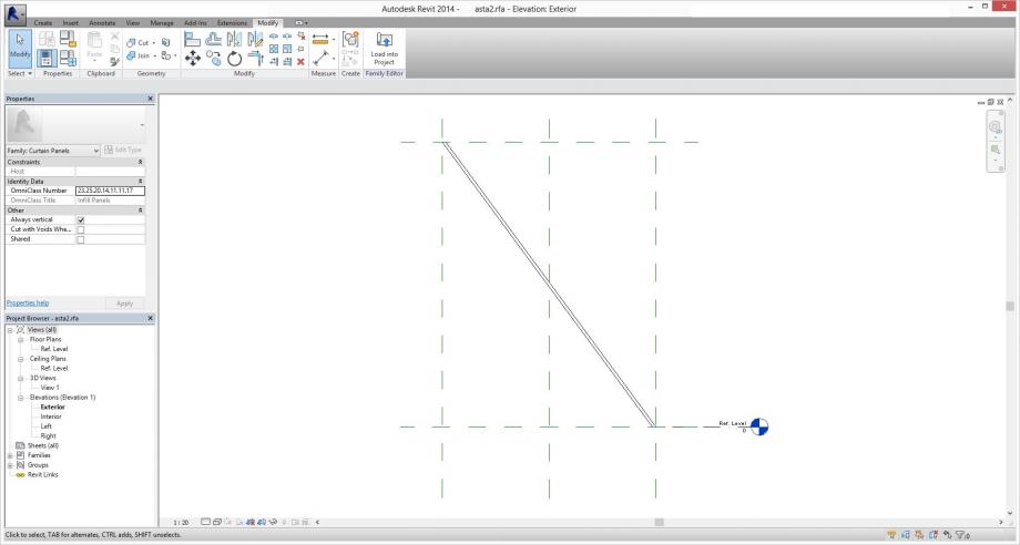
Ora si ripeterà l’operazione per una seconda asta che avrà l’inclinazione opposta alla precedente.
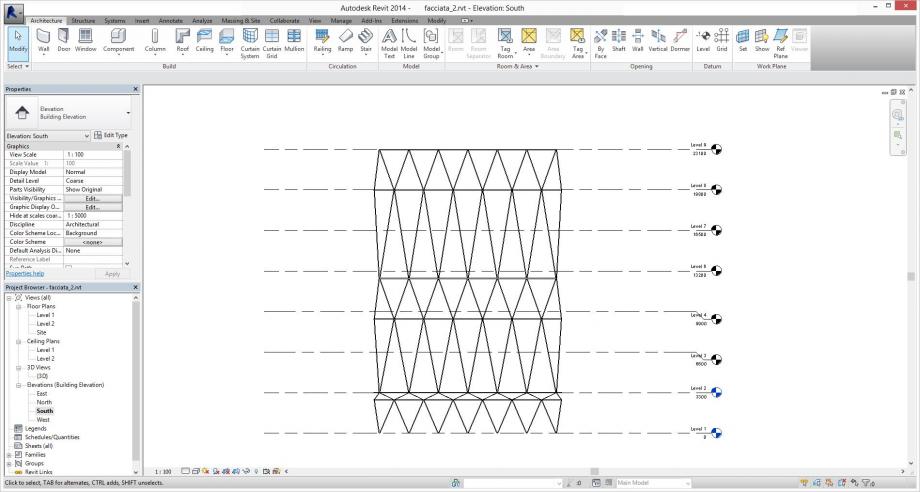
Possiamo ora passare all’ambiente di progetto, in cui andremo a definire la geometria della facciata. Apro quindi un nuovo file project che utilizzi il template “architectural”.
Nel menù architecture uso il comando wall, definendo dal menù a tendina la famiglia “curtain wall”.
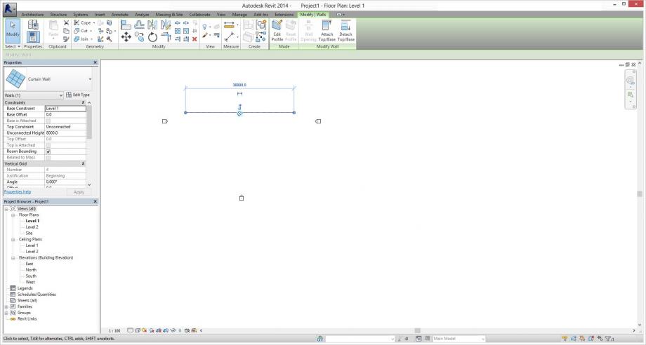
La lunghezza in pianta si definisce tramite la “quota provvisoria” che compare automaticamente, le altezze di base e sommità possono essere gestite dalla finestra delle proprietà.
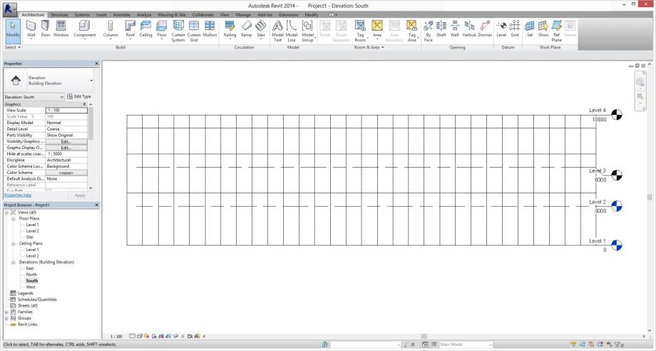
Su questa superficie si può ora disegnare una griglia, tramite il comando “curtain wall grid” (mi viene da chiedere:la griglia può essere solo ortogonale, e solo retta? Non credo ma non ho saputo scoprirlo!).
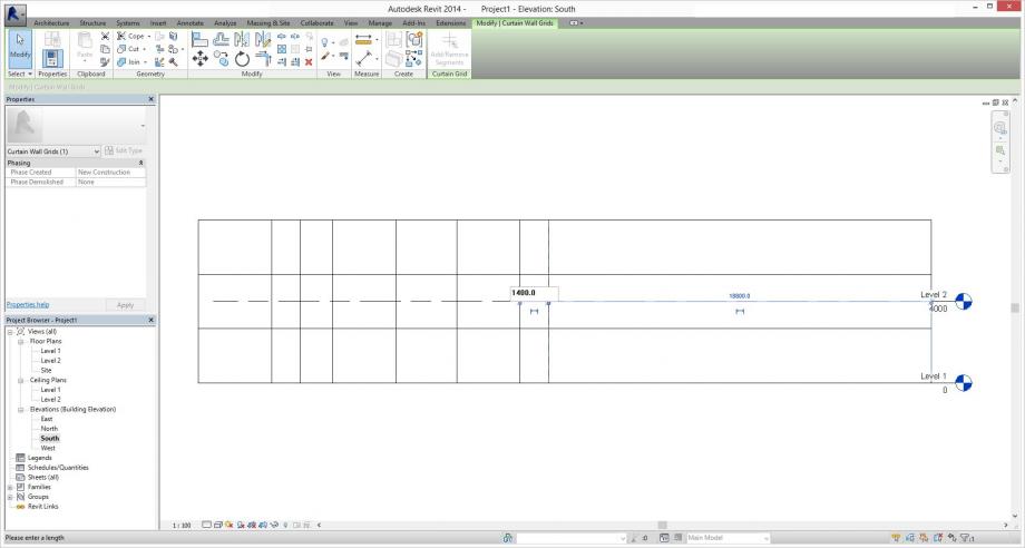
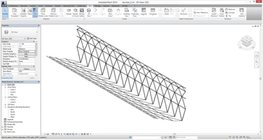
Vado ad alzare fino ad un ipotetico quarto livello la facciata, per permettere una maggiore variazione nei risultati.
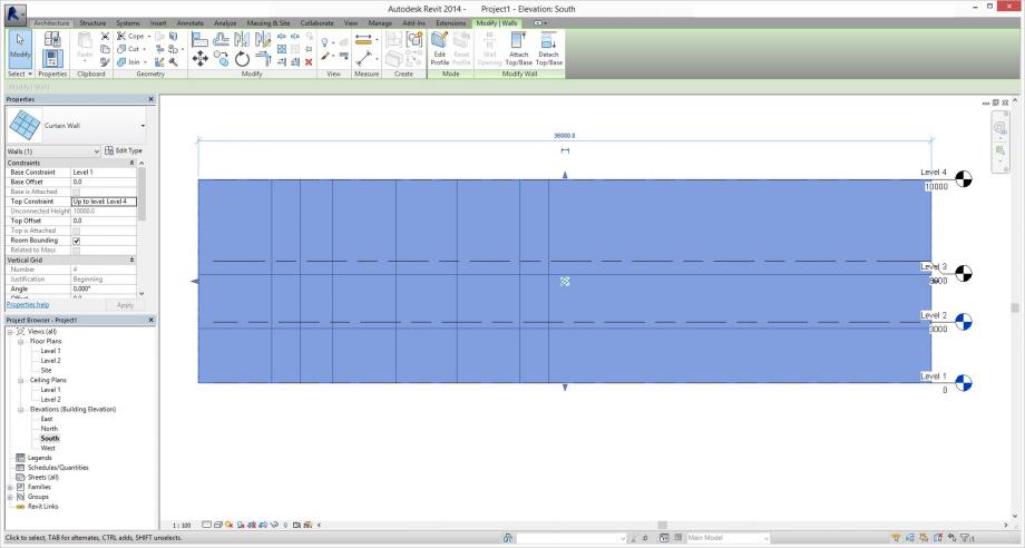
Vado quindi a definire una griglia di 1,2 m di larghezza e altezze variabili da 4 a 1 m.
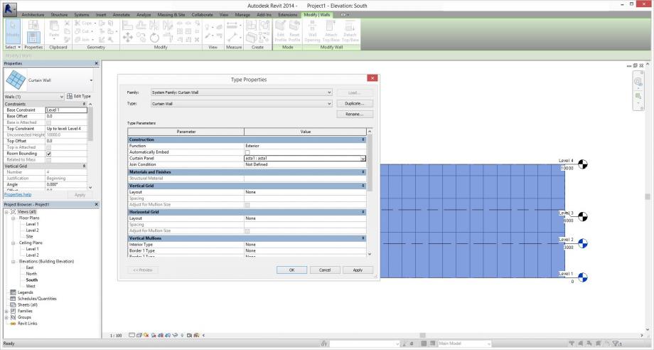
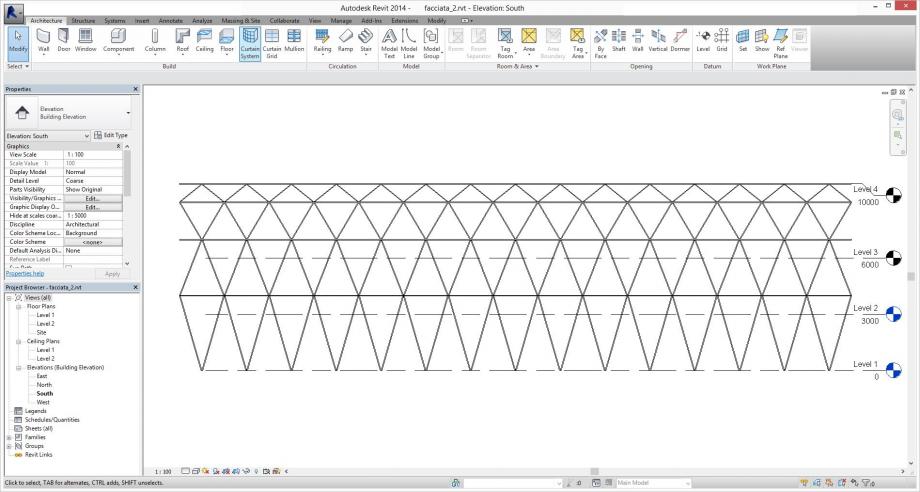
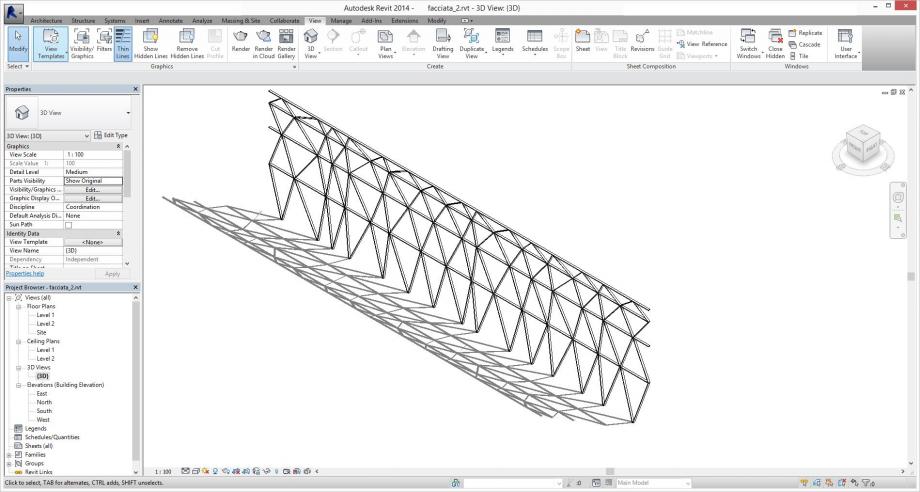
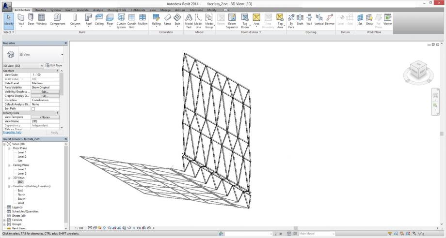
Dopo aver importato le due famiglie delle aste nel progetto tramite il comando “load into project”, possiamo andare ad associare alla griglia i moduli da noi modellati: entrando nelle type properties del curtain wall si può vedere che alla voce “curtain panel” non è assegnata alcuna famiglia. Dal menù a tendina scegliamo quindi la famiglia di una delle aste.
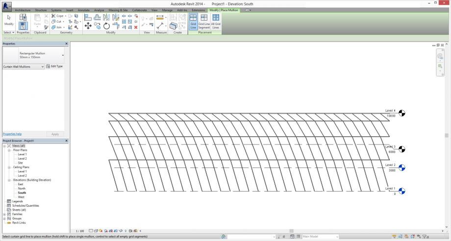
Vediamo che ora ad ogni modulo della griglia corrisponde un’asta. Per rappresentare i traversi orizzontali che andranno a chiudere la maglia triangolare della facciata possiamo anche direttamente usare il comando “mullion”, che potremo posizionare sulle grid lines che selezioneremo. Le dimensioni e la disposizione sulla profondità di questi montanti possono essere gestite sempre dalle type properties del curtain wall.
Per applicare ad uno specifico modulo un pannello diverso da quello assegnato al tipo, possiamo selezionarlo (si ricorda l’uso del comando TAB per scorrere tra le possibili selezioni) e, cliccando sulla puntina azzurra, rimuovere il pin: sarà ora possibile (ovvero non sarà più opacizzato nella finestra delle proprietà) cambiare il pannello a cui il modulo è associato.
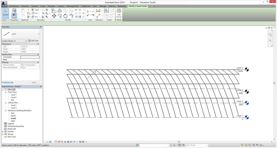
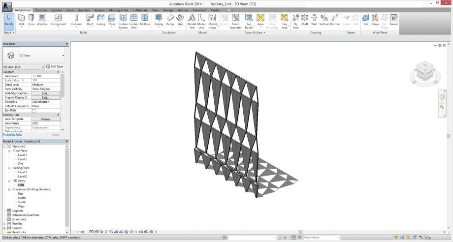
Ho quindi provato ad organizzare la facciata in moduli triangolari (si poteva progettarla anche in altri modi!).
Il punto che mi premeva sottolineare era la possibilità di ottenere una variazione non dalle caratteristiche del pannello, ma dalle dimensioni della maglia, come cercherò di mostrare in seguito:
Vediamo un primo tentativo:
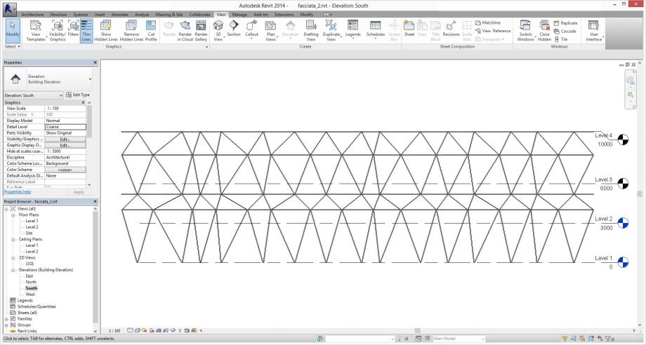
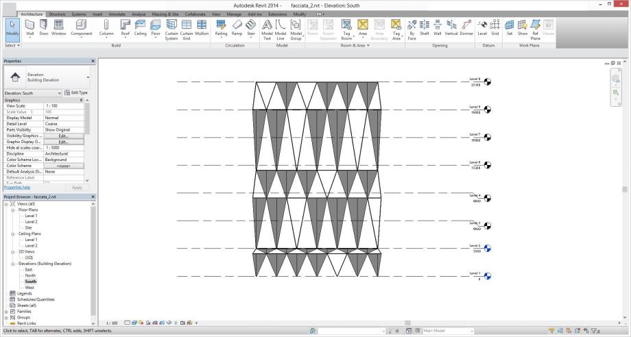
Ora osserviamo come la variazione della larghezza dei moduli provochi una sorta di “effetto distorto”, composto di triangoli tutti diversi.
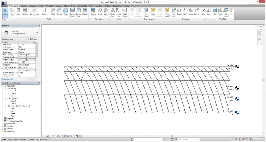
Anche la diversa disposizione in altezza dei montanti orizzontali cambia di molto l’aspetto della parete:
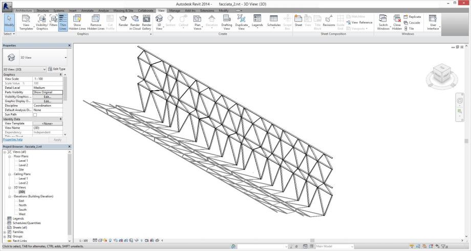
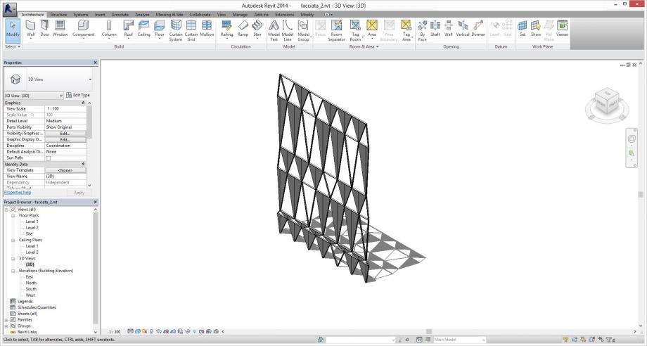
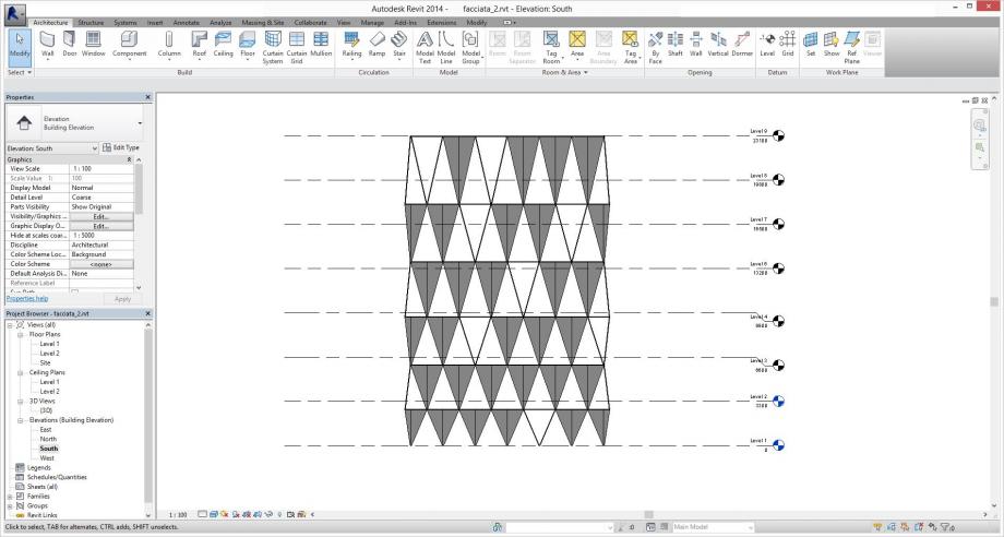
Per rendere questi tentativi un po’ più tangibili, ho provato a definire una parete con delle dimensioni ed uno scopo definiti: ho immaginato la facciata di un edificio, ad esempio ad uso uffici o commerciale, inserito in un contesto urbano (del tipo urban infill, per cui totalmente caratterizzato dal solo prospetto su strada). Tale edificio si sviluppa su 7 piani, ai quali la griglia si rapporta in modo sempre diverso:
Per non avere una facciata completamente vetrata, si può immaginare che alcuni di questi moduli triangolari siano resi opachi. Per fare ciò andremo ad aggiungere altre due famiglie di curtain panel, questa volta modellati come triangoli estrusi.
Questi pannelli possono andare a sostituire le corrispettive aste, ad esempio in questo modo:
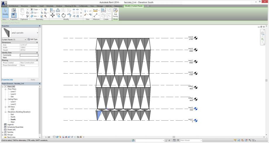
In un’ultima variante ho alternato i moduli “bucati” con quelli “opachi”.
Se immaginiamo che questi pannelli siano ad esempio di lamiera metallica, traforata o grecata, possiamo pensare a tale superficie come ad un sistema di brise soleil. Altrimenti potrebbe costituire il caso di una vera e propria facciata modulata nelle sue aperture su questa matrice triangolare.
Ricordo inoltre che è possibile in ogni momento cambiare ulteriormente la geometria della griglia.
Mar, 09/12/2014 - 19:02
 Giovanna Maria M.
Lun, 08/12/2014 - 20:51
Giovanna Maria M.
Lun, 08/12/2014 - 20:51
La quarta consegna consiste nel creare COMPONENTI DI FACCIATA, inziamo con il "first step":
1 - IMPOSTIAMO LA PAGINA DI PROGETTO
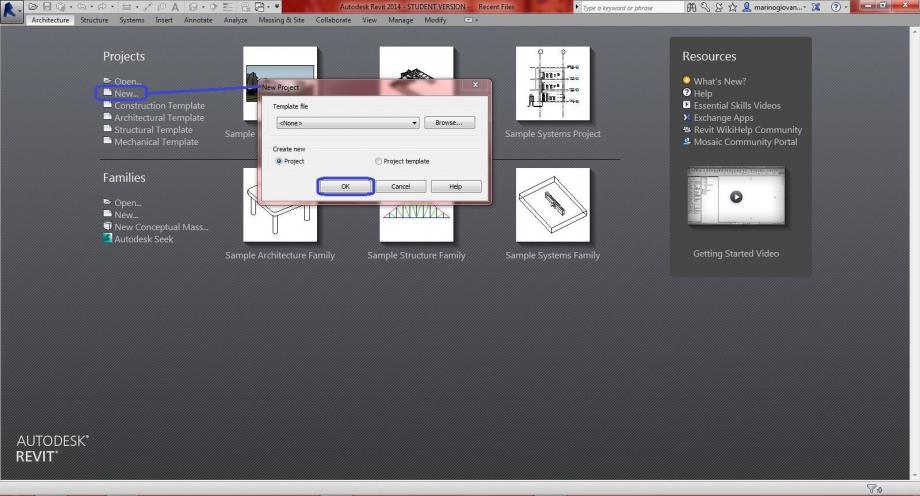
Apriamo un nuovo progetto: New - Project - OK
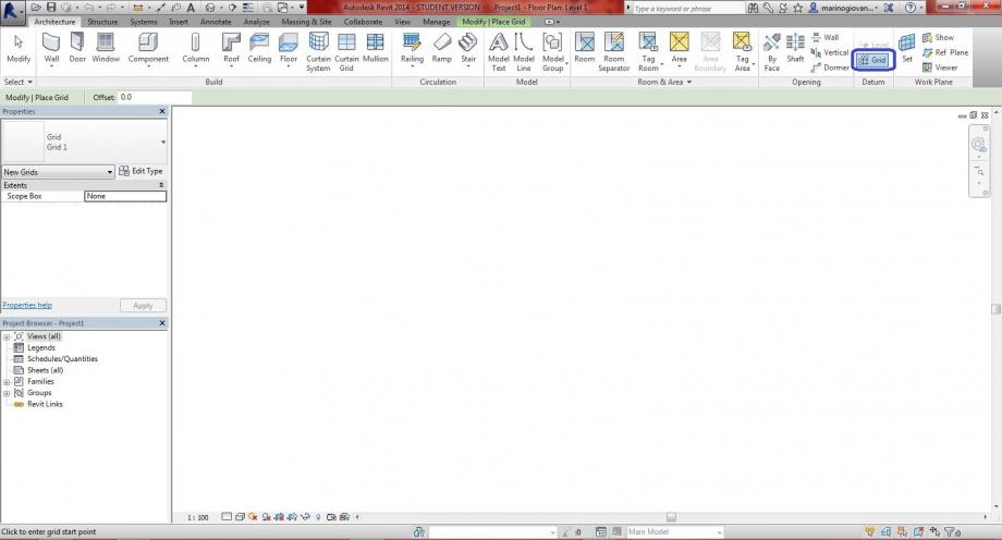
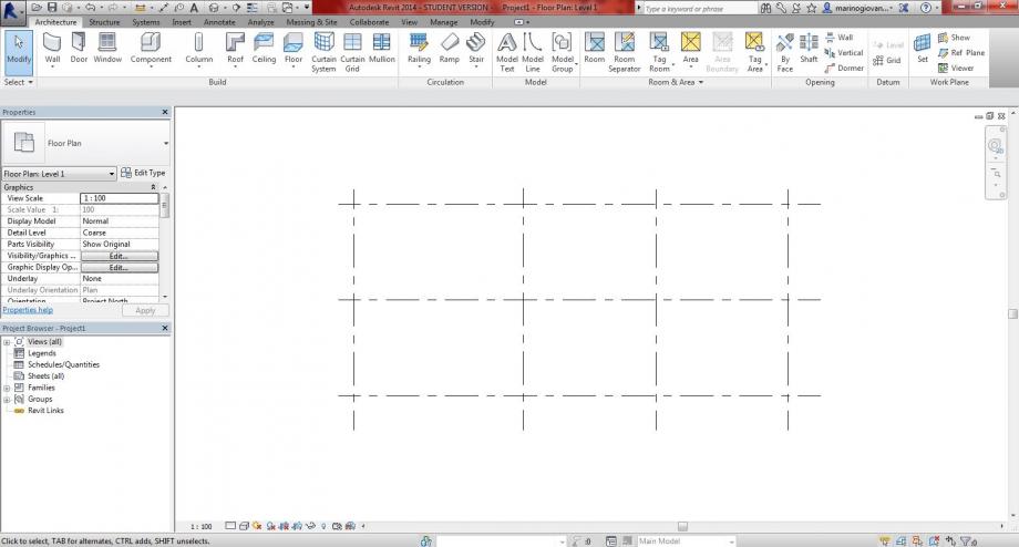
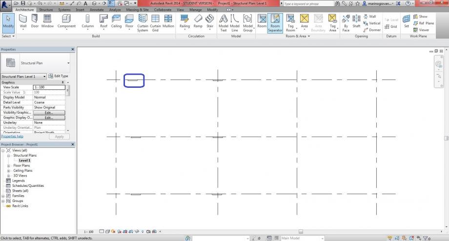
creiamo la nostra griglia, cliccanco il tasto: Grid - sia linee verticali che orizzontali (anche in diverse distanze)
2 - ESEMPIO DI PRIMO COMPONENTE
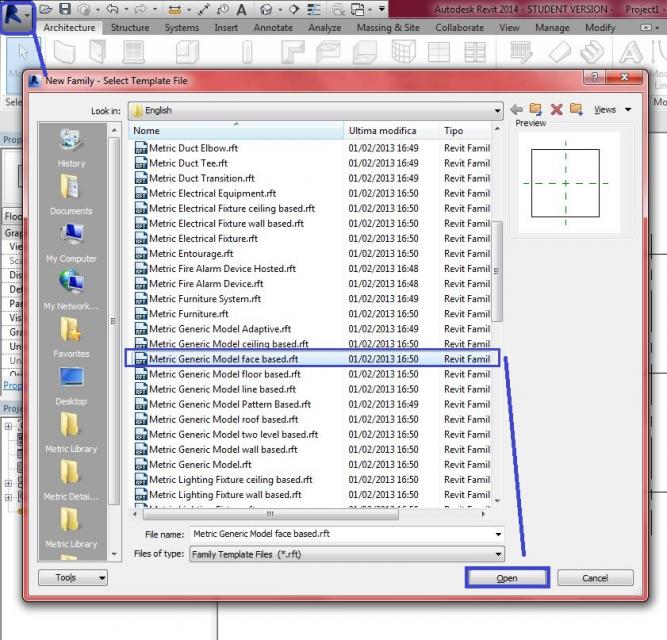
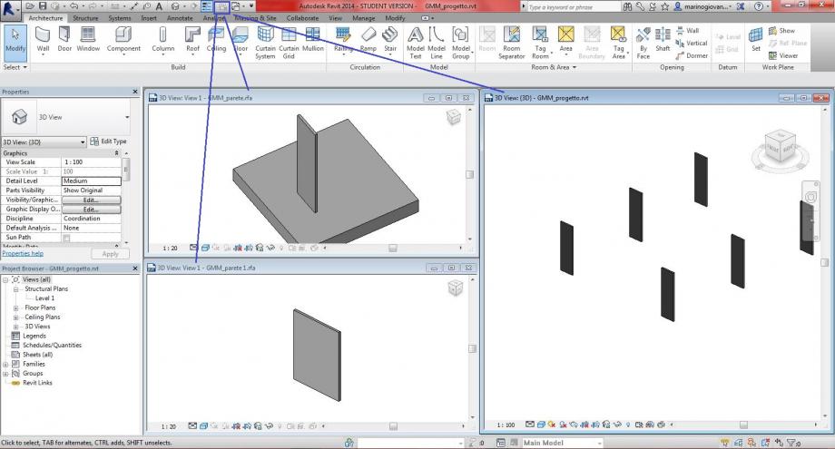
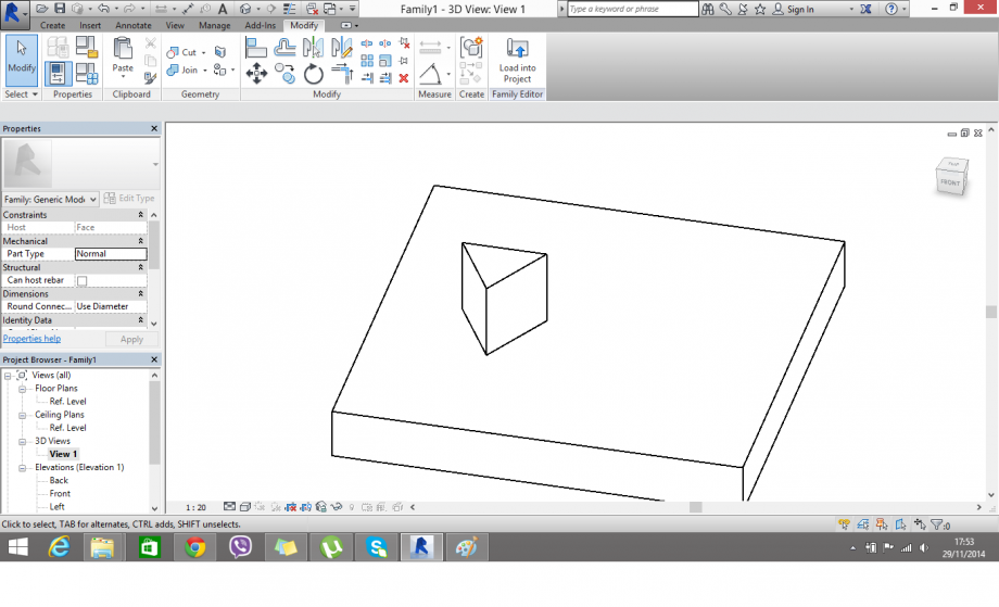
Il primo componente lo creiamo con: New - Family - Metric Generic Model Face Based - Open
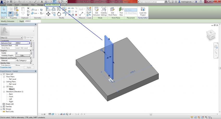
come ho fatto per le altre consegne, creiamo l'elemento con: Create - Extrusion - Rectangular - (Extrusion End - 2m) - 
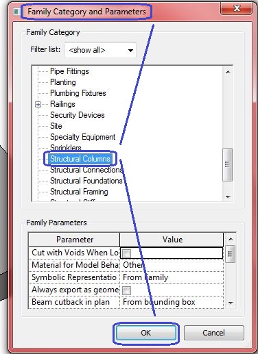
Family Category and Parameters - Structural Colums - OK
ritorniamo al progetto trasportando l'elemento creato: clicchiamo l'elemento - Load into Project - Work Plane
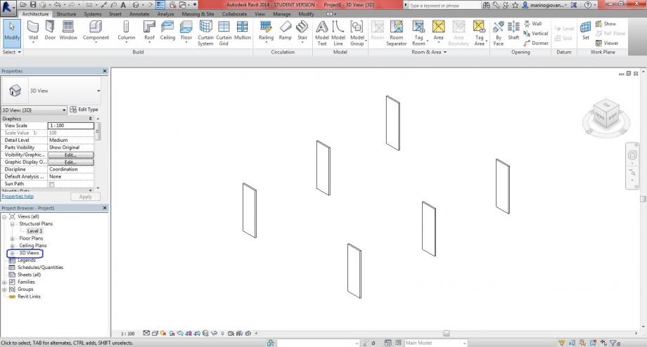
vista 3D Views
3 - SECONDO COMPONENTE
New - Family - Metric Curtain Wall Panel - Open
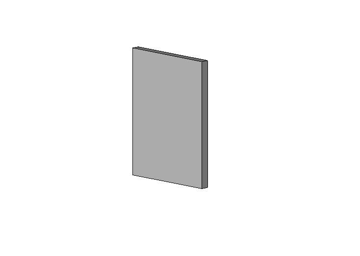
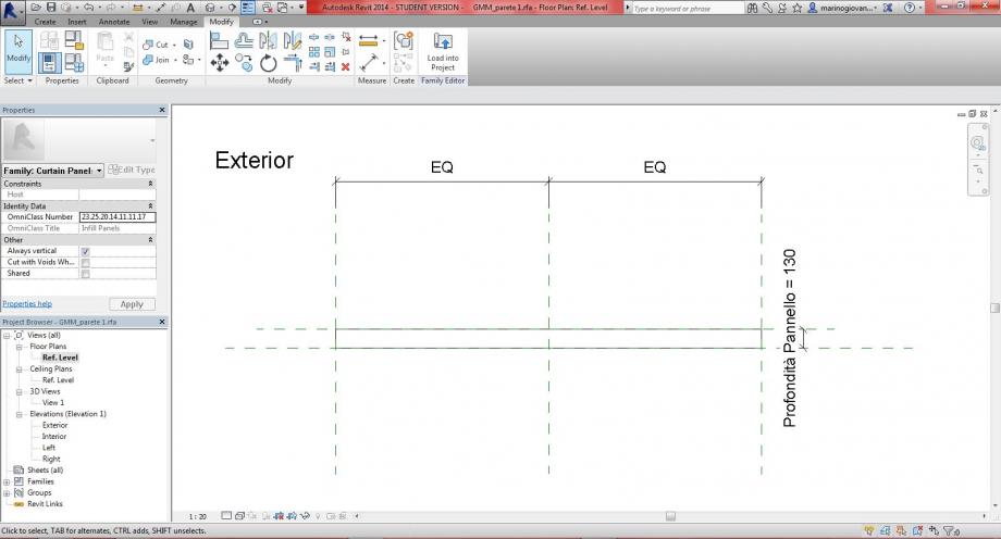
creiamo l'elemento portandoci in vista Exterior: Create - Extrusion - Rectangle - 
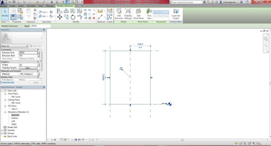
allineamo i lati con i piani di riferimento: clicchiamo il tasto Align e chiudiamo tutti i lucchetti
questo è il risultato
vista 3D Views
cambiamo vista: Ref. Level - Properties - Name "Estensione Pannello" - Align (tra la linea e il piano di estensione) - chiudere il lucchetto
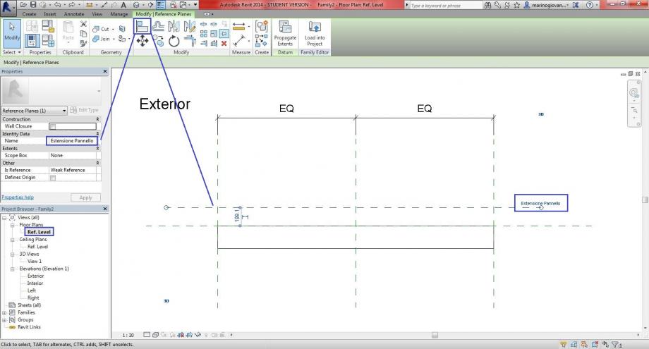
qui viene rappresentato in modo migliore il "post allineamento" e chiusura lucchetto
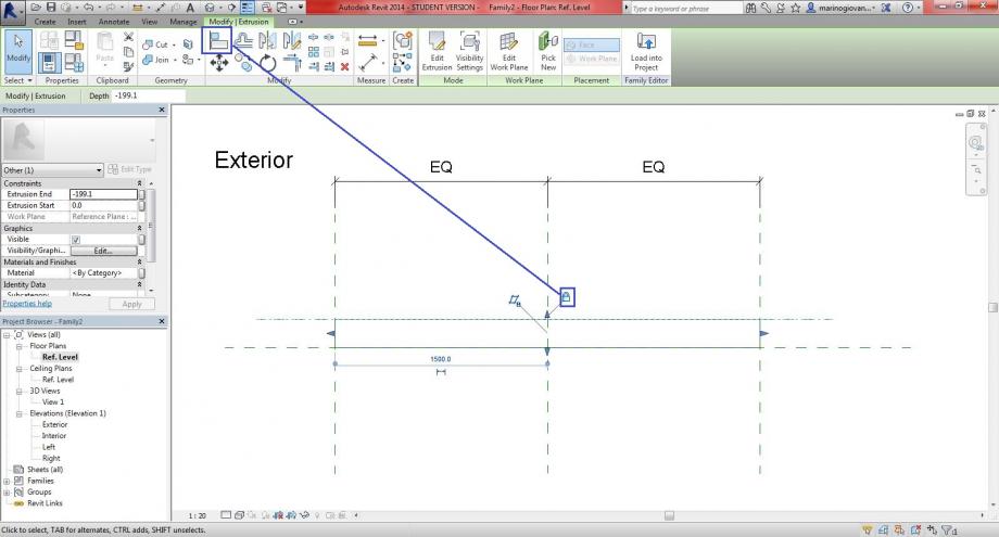
inseriamo la dimensioni e la nominiamo cliccando: Alligned Dimension - Parameter Properties - Name "Profondità Pannello" - Instance - OK
modifichiamo la dimensione da 199 m a 130 m
4 - SALVARE E CHIUDERE FINESTRE IN PIU'
salviamo sia il progetto, fin ora creato, e sia le due famiglie come: Save As - Project or Family - File Name (sigla identificativa)_(nome del file), es.: GMM_progetto
le finestre che sono in più di uno stesso file possiamo riduarle a tre come: cliccando il tasto in alto Close Hidden Windows
5 - LAVORIAMO SUL FILE PROGETTO
impostiamo la vista in pianta: Level 1
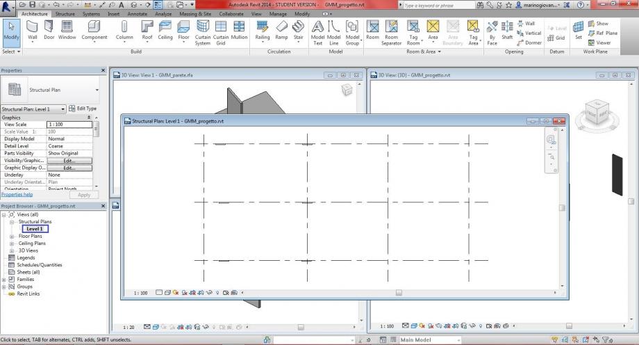
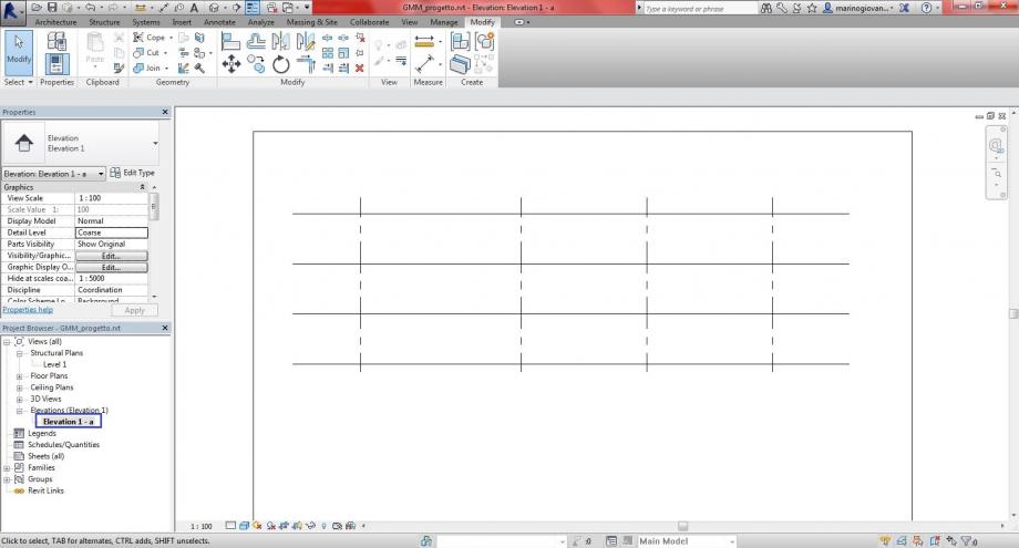
View - Elevation -  - stendiamo i margini blu per tutta la griglia
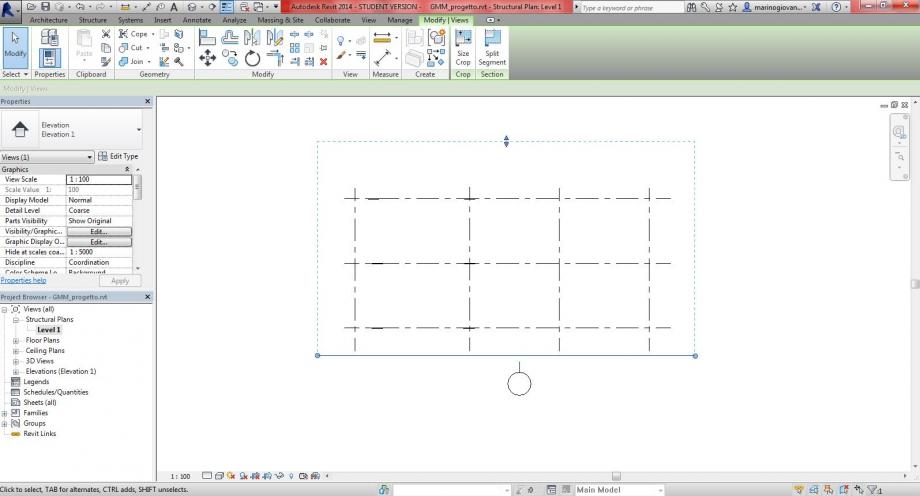
nel Project Browser compare una nuova vista - Elevation 1 - a
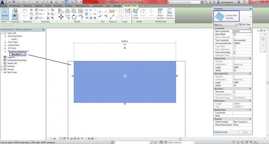
ritornando alla vista Level 1 clicchiamo il tasto: Wall - Wall Architectural - Edit Type (Properties) - System Family: Curtain Wall - Curtain Wall 1 - Duplicate - Name: Facciata - OK (fino a chiusera finestre)
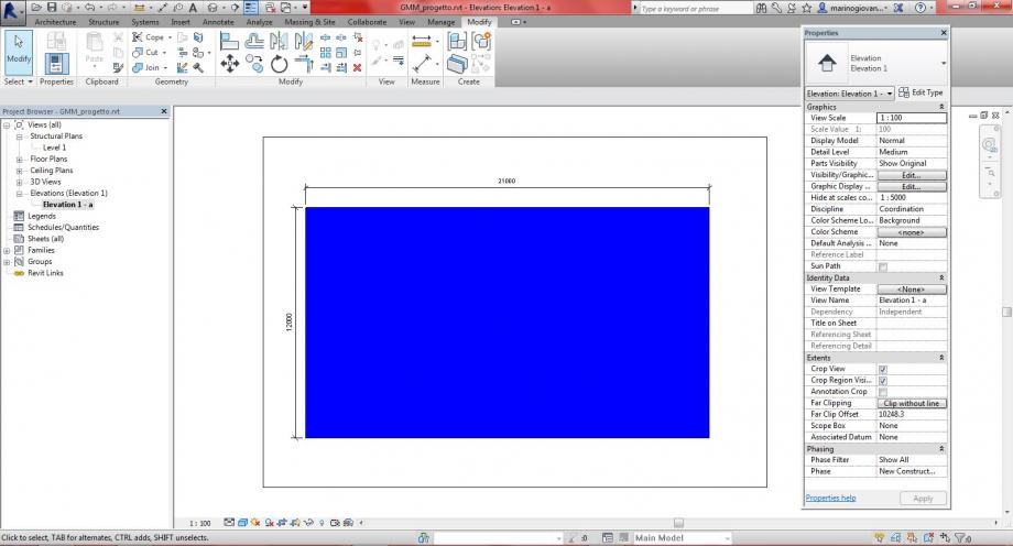
cliccando le linee sia verticali che orizzontali, tasto destro - Hide in View - Category

impostiamo lo stile di visualizzazione: Shaded (compare il quadro blu)
impostiamo le misure: Edit Type - System Family: Linear Dimension Style - Quota Metri - Units Format (Meters - 2 decimal places - m - OK) - OK (chiusura delle finestre)
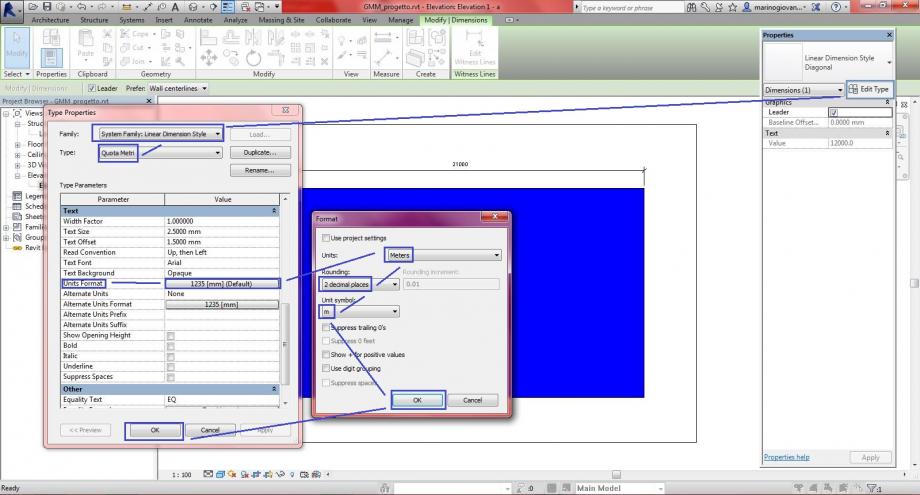
questo sistema (che ho scritto in alto) lo impostiamo per entrambe le dimensioni basta cliccare il tasto: Match Type Properties

- creiamo una griglia: Architecture - Curtain Grid (creiamo sia linee verticali che orizzontali)
- dopo Load into Project del file GMM_parete1 - al GMM_progetto
- Project Browser - Curtain Panels - Emptu System Panel - GMM_parete1
- Cliccare parete blu - Edit Type - Curtain Panel - GMM_parete1 - Apply - OK
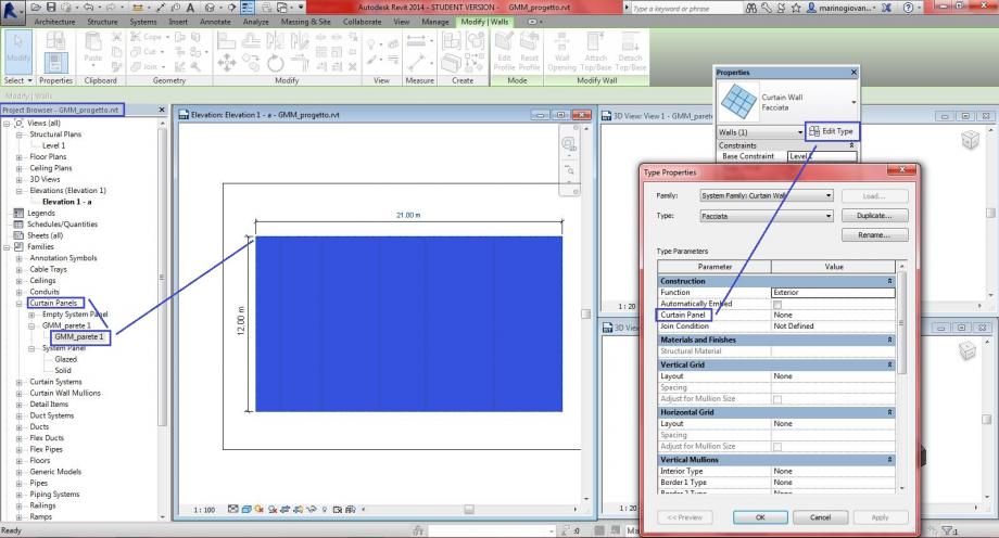
dimensioni: 21m x 12m
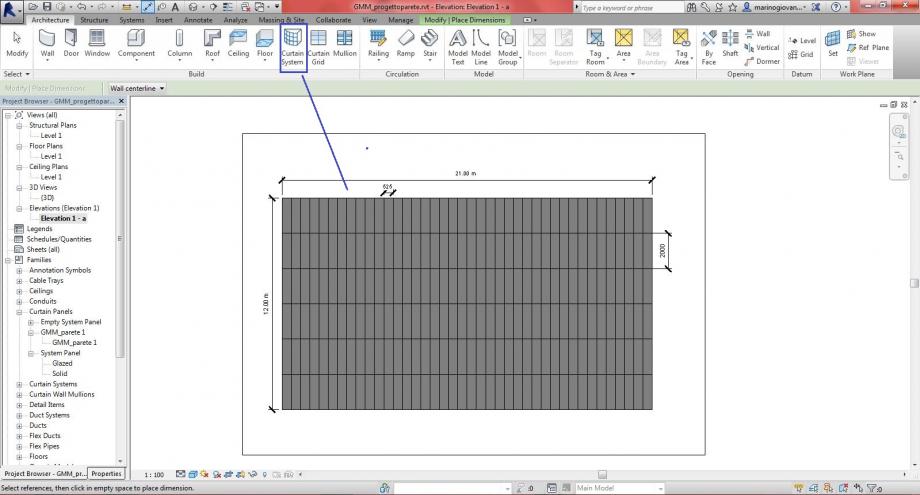
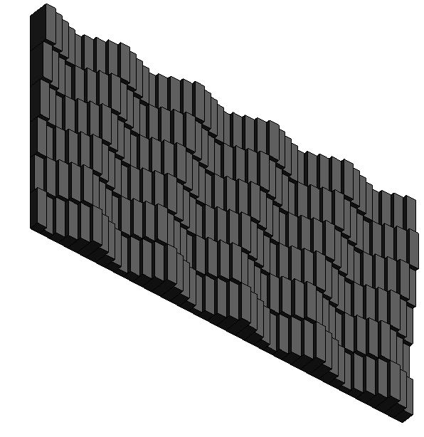
clicchiamo ogni singolo quadrato e cambiamo gli spessori, così da combiare una PARETE.
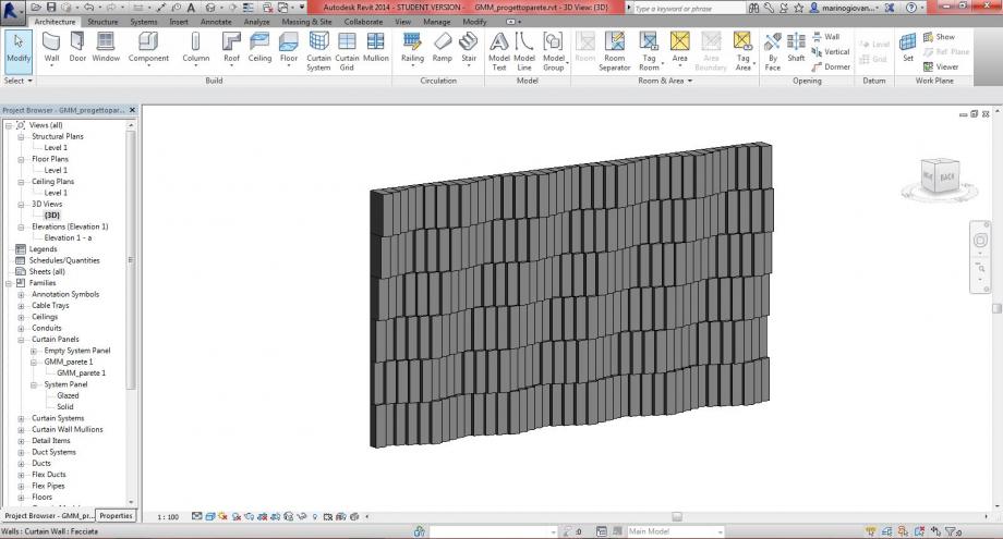
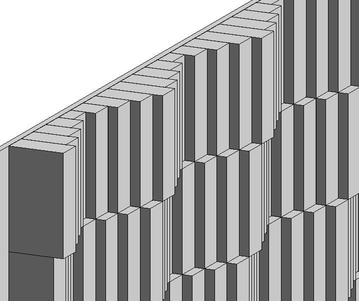
vista 3D - FACCIATA con MOVIMENTO ARMONICO (o a nastro) . Inoltre ho inserito come immagine principale della facciata le "canne dell'organo" perchè? la mia idea è di creare qualcosa di visibile ma cradualmente.
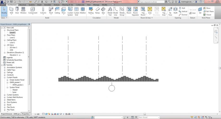
vista Level 1
 marianagregori
Lun, 08/12/2014 - 20:55
marianagregori
Lun, 08/12/2014 - 20:55
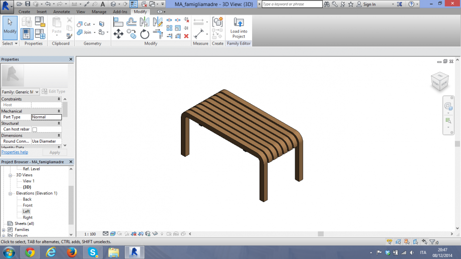
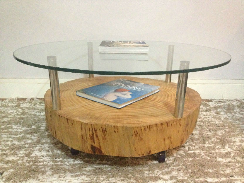
Ho cambiato il mio oggetto perché volevo fare qualcosa tettonica. a questo motivo ho scelto un tavolo parametrico.
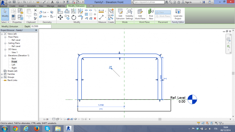
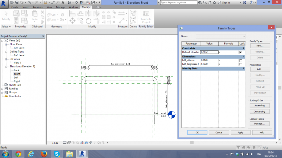
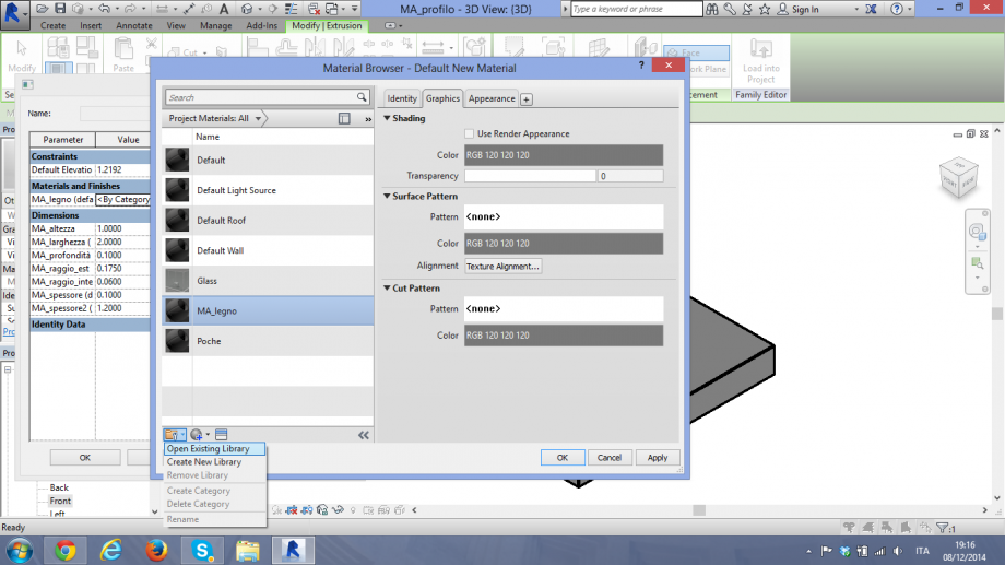
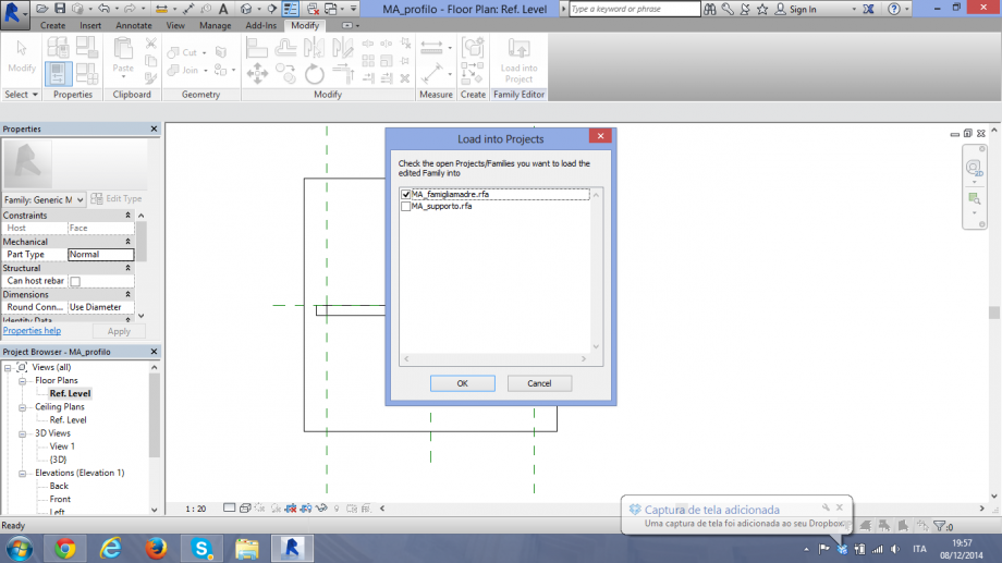
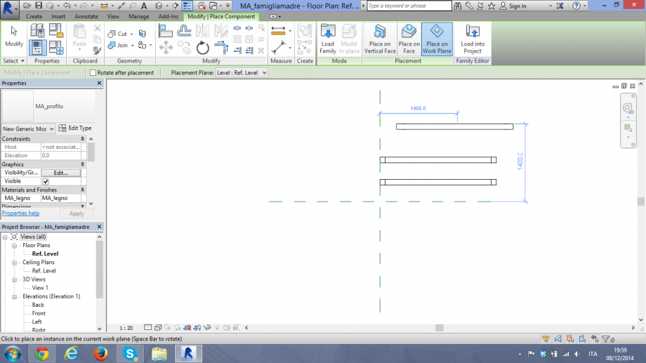
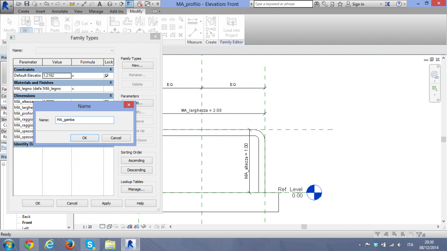
in prima parte ho fatto una famiglia per rappresentare la parte di legno, ossia, la gamba e il piano. ho dato il nome di MA_profilo
1.MA_profilo
primo, ho fatto una estrusione per disegnare il profilo del tavolo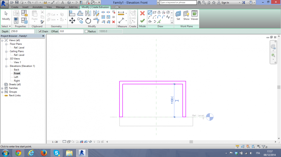
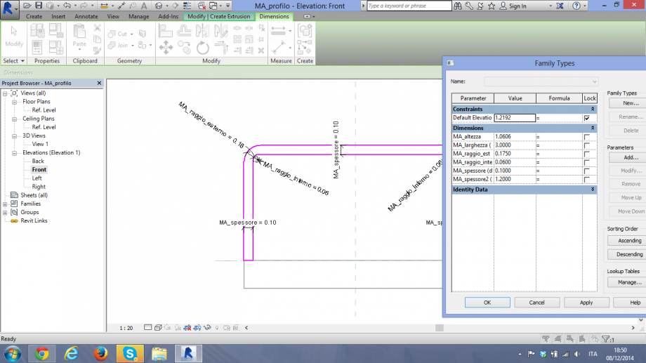
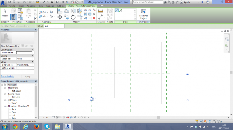
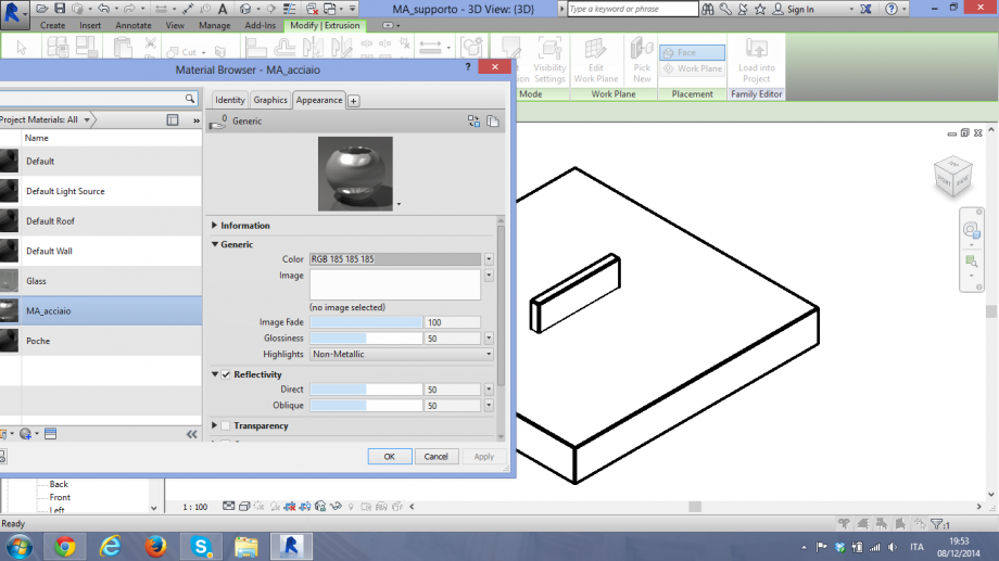
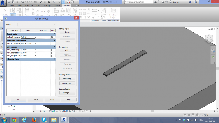
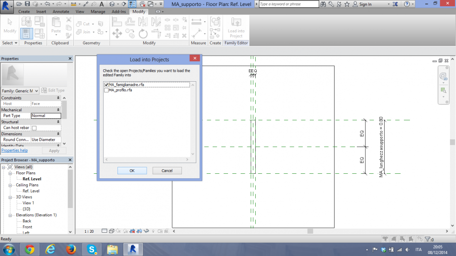
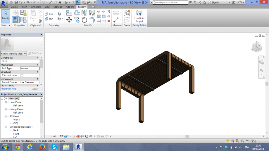
2.MA_supporto .
Adesso, ho fatto la parte tettonica, voglio dire, l'elemento che attacherà al legno.
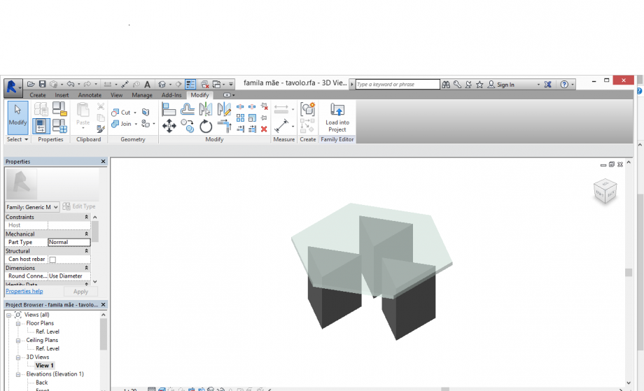
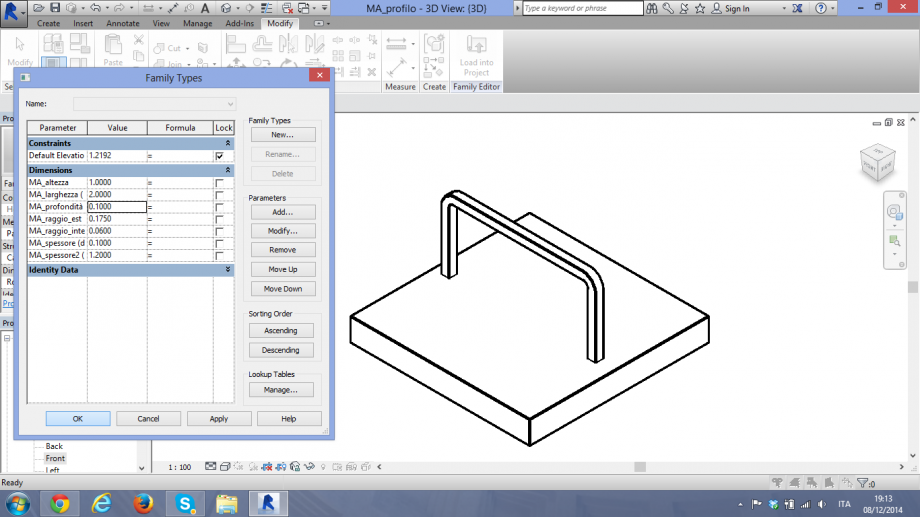
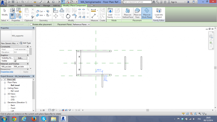
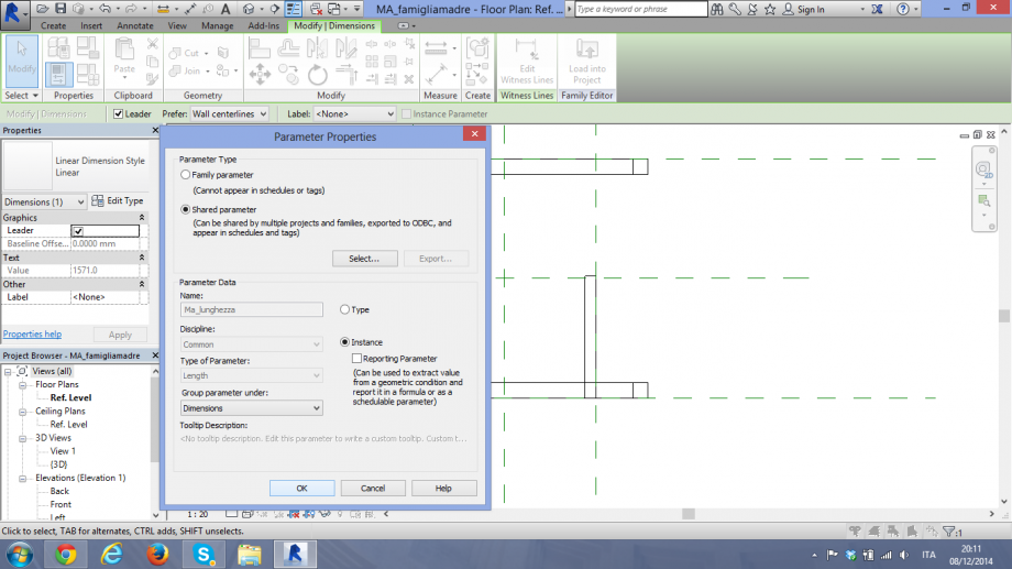
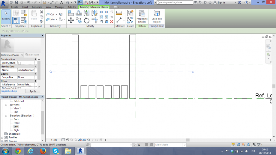
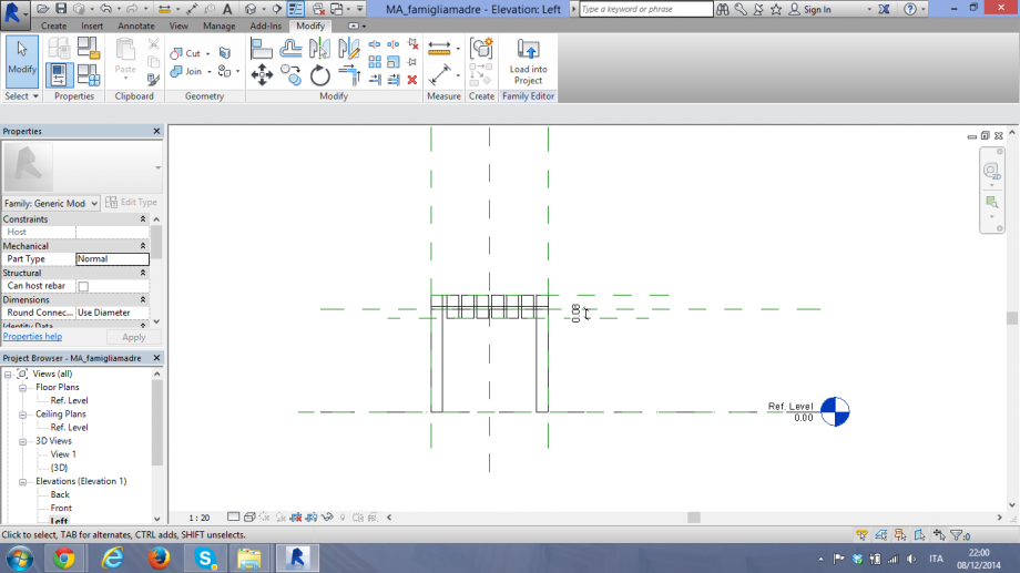
3.MA_famigliamadre
Adesso ho inserito tutti gli elementi in una famiglia madre
Lun, 08/12/2014 - 22:02
 valerio d'ambrosio
Lun, 08/12/2014 - 20:25
valerio d'ambrosio
Lun, 08/12/2014 - 20:25
Le schedules di Revit sono una "vista" in formato tabella di excel del contenuto del file progetto. Rappresentano la possibilità del programma di avere un elenco aggiornato automaticamente di tutti gli elementi che costituiscono il progetto, suddivisi a seconda della tipologia.
Per sperimentare questa fondamentale funzione di Revit ho pensato ad un oggetto composto da pochi semplici elementi che includessero però variazioni di tipo, in modo da avere elementi simili ma distinti nella tabella Schedules.
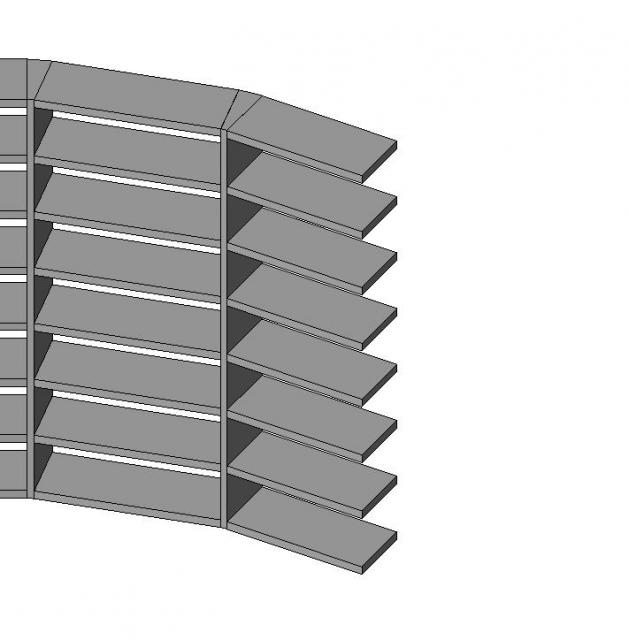
Ho creato una libreria con pannelli verticali ad angolo variabile (usati come dima) e mensole di lunghezza variabile, dimensionati usando una relazione fra l'angolo delle dime e la lunghezza dei ripiani, per cercare di mantenere una curvatura sempre fluida.
La relazione che ho utilizzato è 1 mt/90° = x mt / a°
Esempi:
per una dima da 80° -> lunghezza ripiano = 1 mt x 80°/90° = 0,89 mt. L'angolo relativo fra i due ripiani è di 10°
per una dima da 60° -> lunghezza ripiano = 1 mt x 60°/90° = 0,67 mt L'angolo relativo fra i due ripiani è di 30°
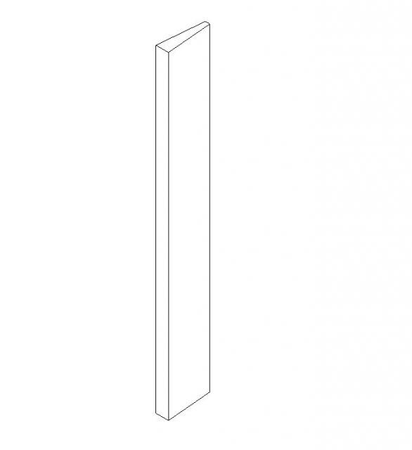
1_ FAMIGLIA DEL PANNELLO VERTICALE AD ANGOLO VARIABILE
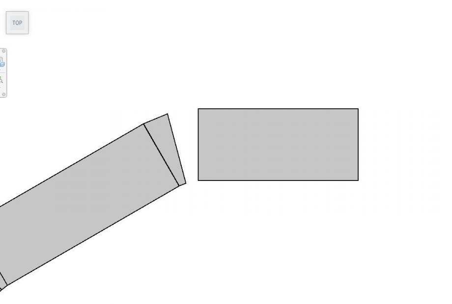
Ho impostato la sezione ad angolo variabile del pannello verticale considerando che la mensola che vi si sarebbe accostata avrebbe avuto sempre lato corto di dimensione fissa (30 cm). Al variare dell'angolo quindi la dimensione y in pianta dell'oggetto varia, ma rimane costante la dimensione del lato obliquo (30 cm). Variando l'angolo automaticamente cambiano il valore H e il lato del trapezio opposto all'angolo. Mentre rimane fisso anche il lato corto della dima.
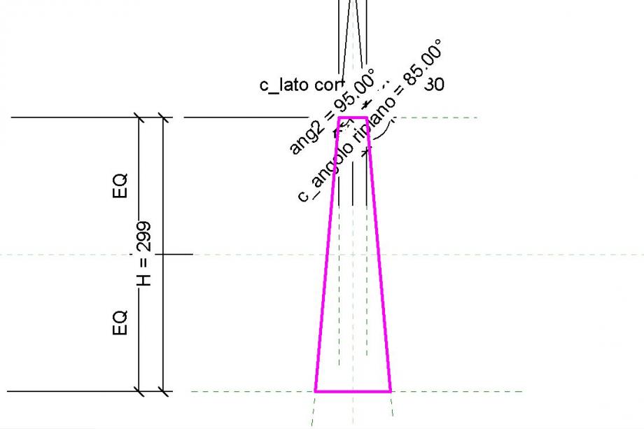
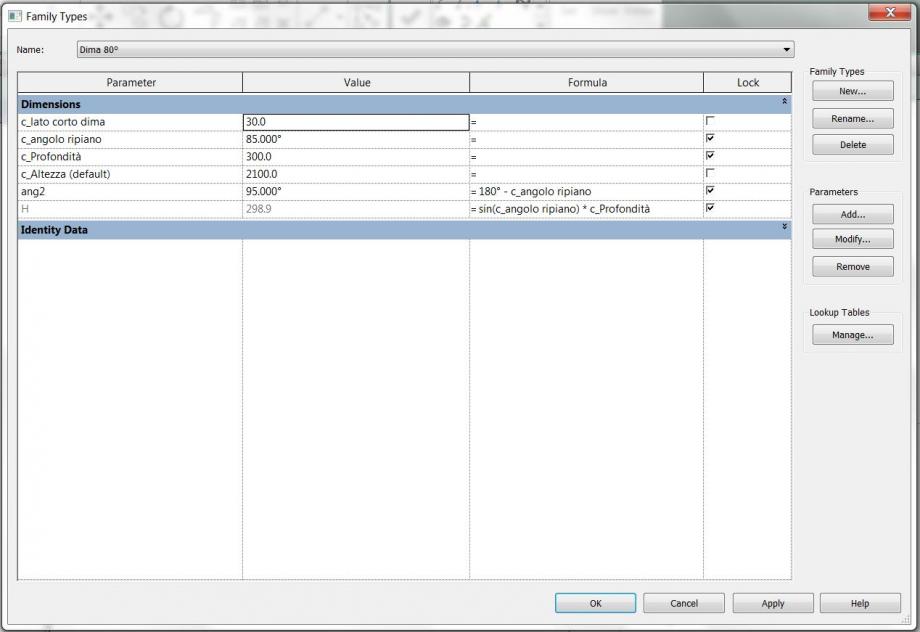
Tutti i parametri utilizzati sono parametri condivisi,tranne H e ang2 che mi è servito per ovviare a uno strano problema che Revit mi dava se applicavo il parametro d'angolo fra due piani. L'altezza è di istanza ed uguale per tutti i tipi che ho impostato.
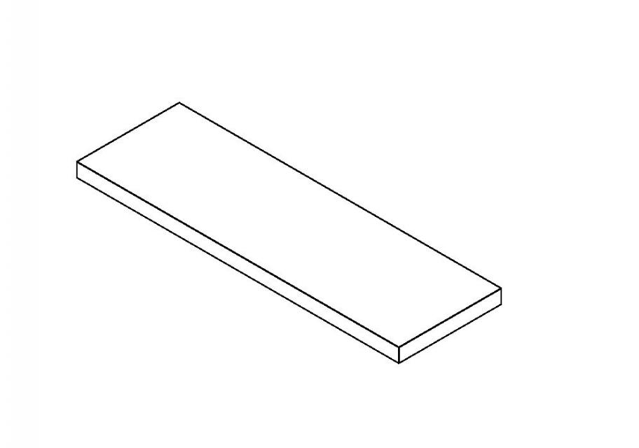
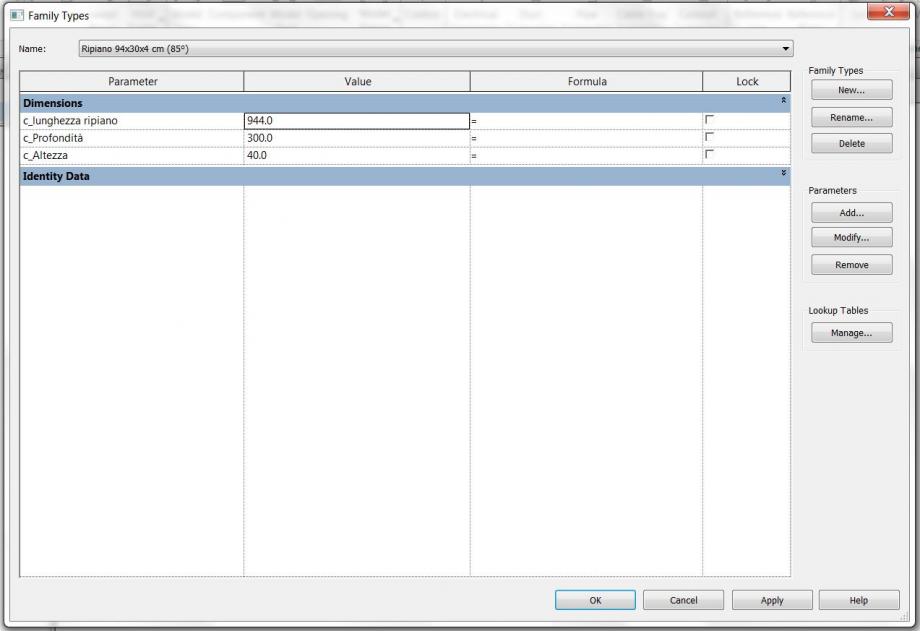
2_ FAMIGLIA DEL RIPIANO A LUNGHEZZA VARIABILE
Il ripiano della libreria è la classica estrusione di rettangolo a cui ho impostato nei tipi delle lunghezze diverse, calcolate secondo la proporzione
1 mt/90° = x mt / a° con a° gli angoli definiti già dai tipi di dima
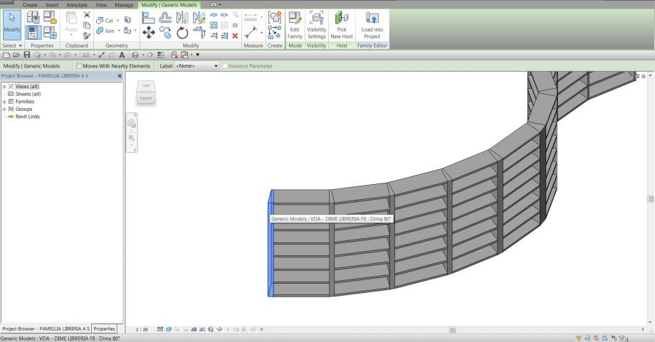
3_ FAMIGLIA MADRE
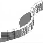
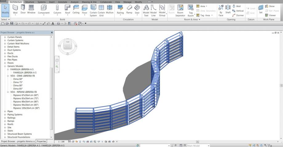
Una volta definite le due famiglie (figlio) ho creato il file family madre, in cui li ho assemblati, utilizzando i comandi allinea o ruota, sposta e array, ho creato senza troppa difficoltà una curva determinata da una successione di elementi ripiano abbinati alle loro relative dime.
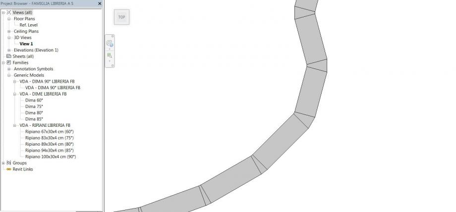
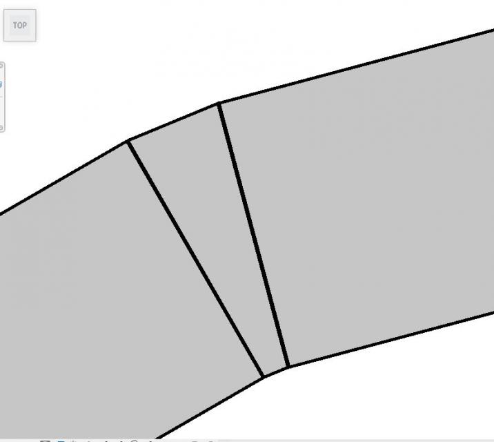
Utilizzando il comando Array ho selezionato i ripiani di quota 0 e ho specificato con la spunta "Last" di poter segnalare l'arrivo dell'ultimo ripiano (quello di copertura) cliccando su uno spigolo di sommità della dima. In questo modo al variare del numero dell' array non cambia lo spazio totale coperto dall'area ma la spaziatura fra i ripiani.
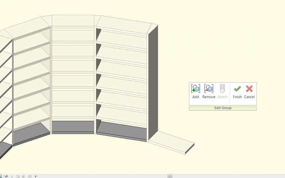
Giocando con le dime ho ottenuto un'idea di libreria dalla forma abbastanza interessante e controllabile (anche molto lunga per la verità), che potrebbe essere un elemento distintivo nella progettazione di un'area consultazione di una biblioteca. Utilizzando diversamente le dime e le mensole associate avrei potuto ottenere curve significativamente più strette o altri elementi curvi più piccoli (delle parentesi..) con cui definire spazi aperti o chiusi. Diciamo anche, per fantasticare, che gli elementi dima e mensole potrebbero essere venduti sfusi per ottenere curve "customizzate"

4_ LA SPUNTA "SHARED"
Questo è un punto a cui tengo dare importanza perchè questa semplice spunta mi ha tenuto in scacco per un paio di giorni! Mi ha bloccato nell'utilizzo delle schedules fino a quando non ho trovato la soluzione su un post del nostro sito. Proprio perchè è un piccolo dettaglio può sfuggire e mettere in difficoltà visto che non è facile trovarlo in mezzo ai tutorial su internet.
Innanzitutto la spunta Shared serve a rendere un singolo elemento di una famiglia visibile nelle Schedules.
Si trova all'interno della famiglia del singolo oggetto; dalla famiglia madre bisogna quindi cliccare sull'oggetto e aprire il file family dell'oggetto
 poi cliccare su Family category parameters e mettere la spunta nel campo Shared.
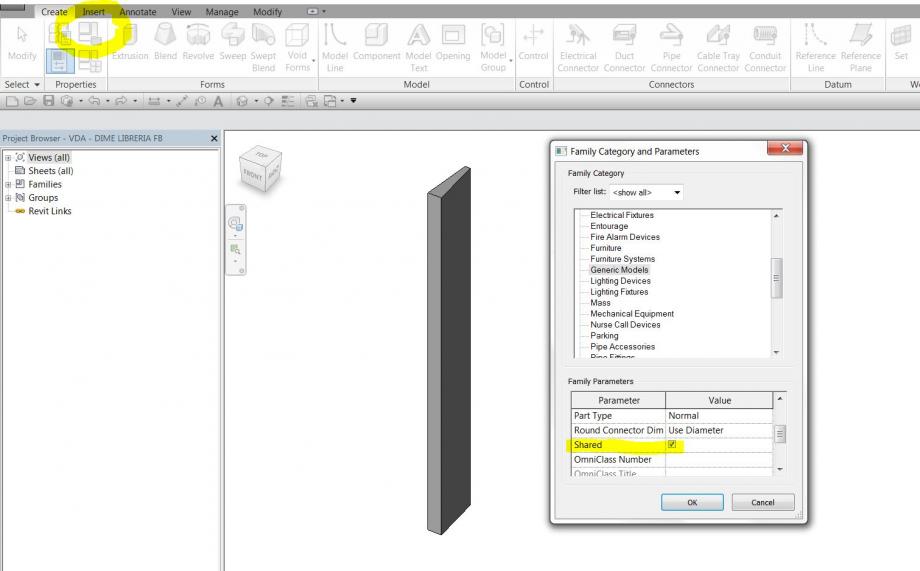 Dopodichè è necessario ripetere l'operazione per tutte le famiglie figlio presenti nel file madre da importare nel progetto.
5_ INSERIMENTO DELLA FAMIGLIA MADRE NEL FILE DI PROGETTO E UTILIZZO DELLE SCHEDULES
Creo un file project generico e ci importo il file madre insieme ai file figlio (i singoli elementi). Importare i file figlio non serve necessariamente ad utilizzarli nel progetto ma certamente è necessario perchè i parametri condivisi ad essi associati diventino visibili nelle schedules.
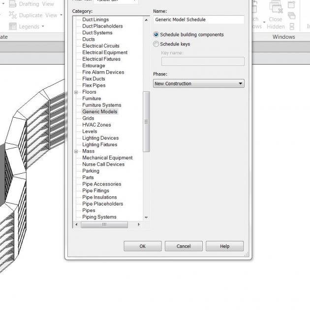
A questo punto sono pronto per impostare la Schedule: dal pannello View clicco su schedules e si apre questa finestra. Indico Generic Models dalla lista, perchè è la categoria di famiglia a cui i miei elementi appartengono e sono quelli che voglio schedulare.
Clicco OK e si apre la finestra scehdule properties in cui posso definire i campi della mia schedule. Scelgo i parametri condivisi che ho contrassegnato con c_ prima del loro nome per non confonderli, poi scelgo anche il campo Family e Count.
con Move Up e Move down posso scegliere l'ordine in cui saranno messi in riga. Clicco su OK

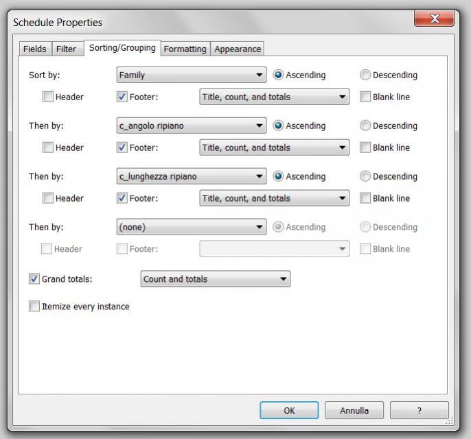
Mi appare la schedule della libreria "in formato grezzo". Per prima cosa posso darle un nome in alto al centro al posto di <Generic Model Schedule>, poi nel pannello proprietà clicco su Sorting/Grouping per modificare il raggruppamento degli oggetti e attribuire nomi e conteggi ai gruppi.

In questa finestra decido se raggruppare in base a una categoria gli oggetti ed in seguito rispetto ad un'altra, se avere un'intestazione o una riga sotto con il totale degli elementi, un totale complessivo alla fine di tutti gli elementi necessari per costruire la libreria. Con la spunta "itemize every istance" scelgo se visualizzare una riga per ogni singolo oggetto. Avendo il conto complessivo per ogni gruppo non mi sembra particolarmente utile, anzi rende meno leggibile la schedule quindi non spunto la casella.
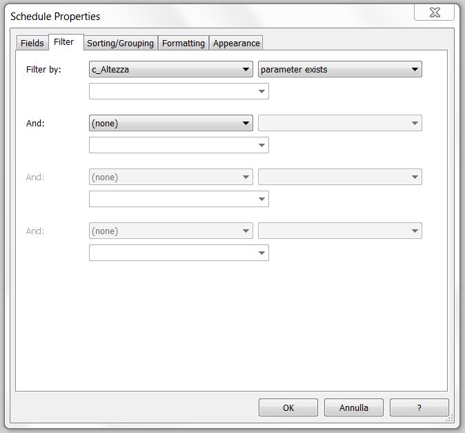
Nel pannello Filter posso filtrare le informazioni a seconda di quello che mi serve: nel mio caso volevo che non comparisse l'elemento della famiglia Madre (di cui sto contando tutti i singoli oggetti), inutile nella schedule visto che ho solo un'istanza nel file progetto. Visto che tutti gli oggetti avevano il parametro c_Altezza tranne la famiglia madre, ho definito il filtro con "parameter exists" e l'istanza della famiglia madre è scomparsa dalla schedule.
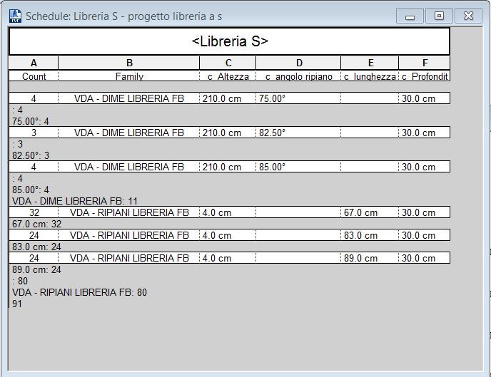
Dopo un po' di modifiche ho ottenuto una schedule molto più leggibile del modello iniziale, e che comunque propriamente rappresenta in termini numerici il progetto, così come nella view3d ho una schematizzazione grafica di esso. Modificando il progetto da adesso la schedule si aggiornerà automaticamente, al variare nella scena degli elementi tabellati.

Di questo sistema mi piace l'idea di poter creare librerie di forme diverse che seguono curve molto differenti (attraverso uno studio preliminare di ricalco di una curva ideale), fino ad arrivare in via ipotetica alla costruzione di librerie circolari possibili usando sempre la stessa dima e la relativa mensola. D'altra parte però è un progetto ancora poco definito in termini di dettagli costruttivi. Sarebbe un'operazione relativamente semplice visto che "da vicino" (nell'intorno della dima) gli elementi funzionano ortogonalmente fra di loro e si comportano come la classica libreria lineare, ma bisognerebbe capire cosa avviene nelle dime così spesse e dalla forma inconsueta.
Lun, 08/12/2014 - 20:26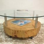 Thyago alves
Lun, 08/12/2014 - 00:46
Thyago alves
Lun, 08/12/2014 - 00:46
- L'idea era di fare un tavolo per un soggiorno
- in un primo momento ho fatto un file madre e salvato, poi ho fatto le famiglie che compongono i file in faced base
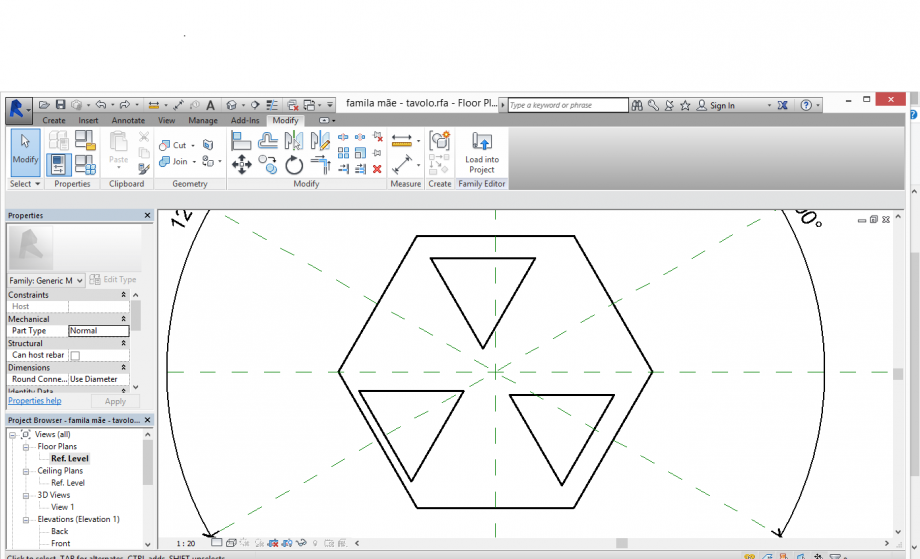
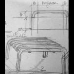
- prima era impostato un triangolo da un lato e due angoli
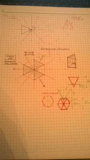
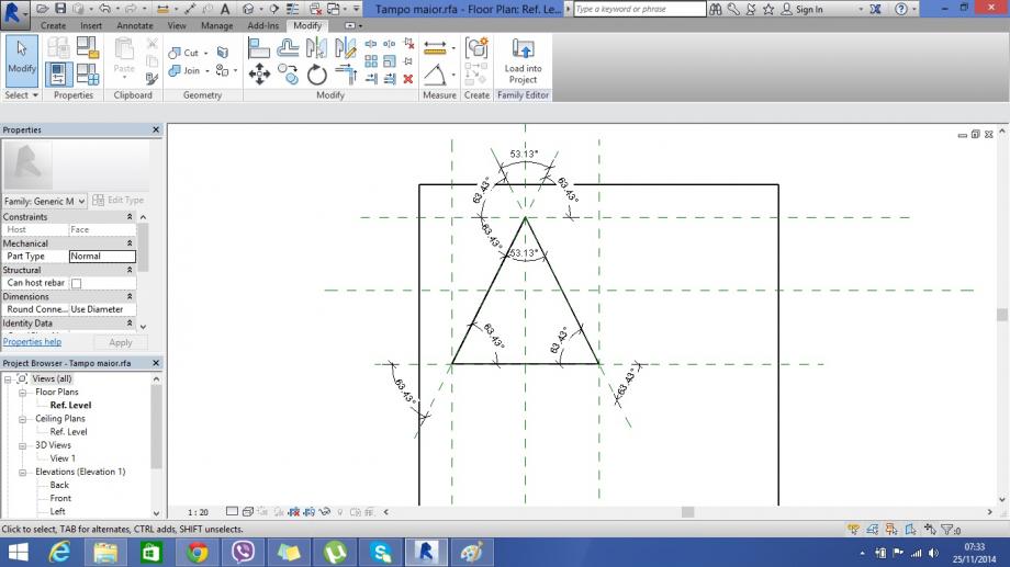
 poi ho fatto la parametrizazzione dell esagono e Ho esportato e famiglie al file madre per formare un unico file