 laura.vellucci
Gio, 11/12/2014 - 09:48
laura.vellucci
Gio, 11/12/2014 - 09:48
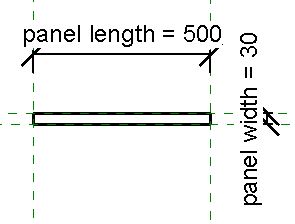
Change the parameter in the file “LV_ DimaA” with the shared Parameter and delete parameter “DimaWidth”
In the next way:
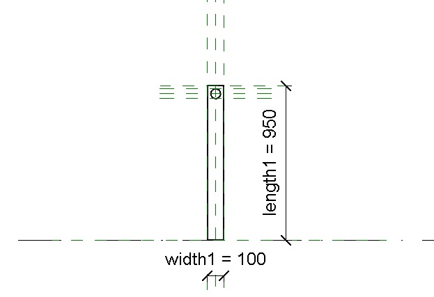
Create the family “LV_Assi2” from “metric generic model” to do the storeys of the library.
In the “LV_progettoMultifunzione” change the unit project from mm to cm.
Then do the holes for mounting to all object
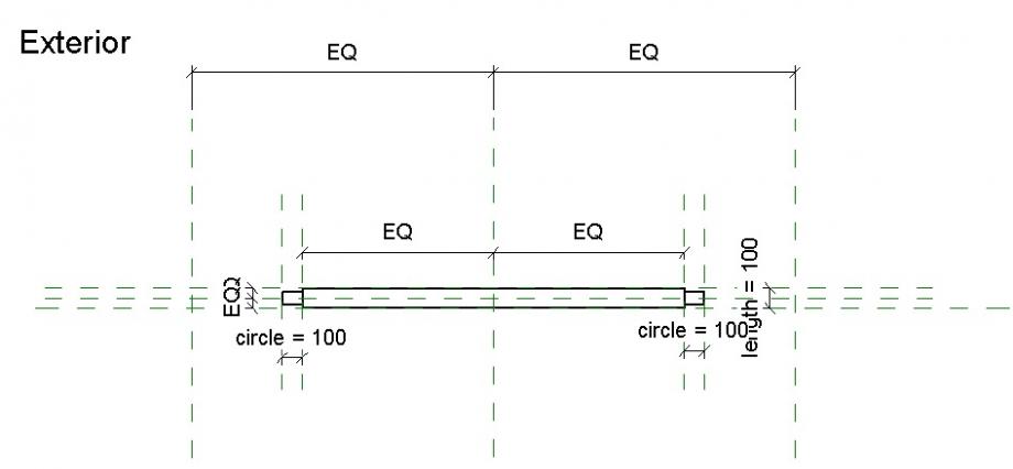
Holes have diameter of 8 mm.
Do first for “LV_DimaA” changing the extrusion of the dima

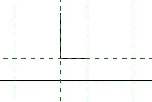
Then do holes for "LV_ProfileA" beginning with the first hole creating a "void form" and creating the parameter for the position.

So can change the position of the hole into the “LV_Multifunzione”.
Do the others holes in the same way.
Do the same for the “LV_ProfileB”
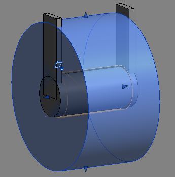
Create a new family the "threaded rod"
Now put into the project the rod and the spacer.
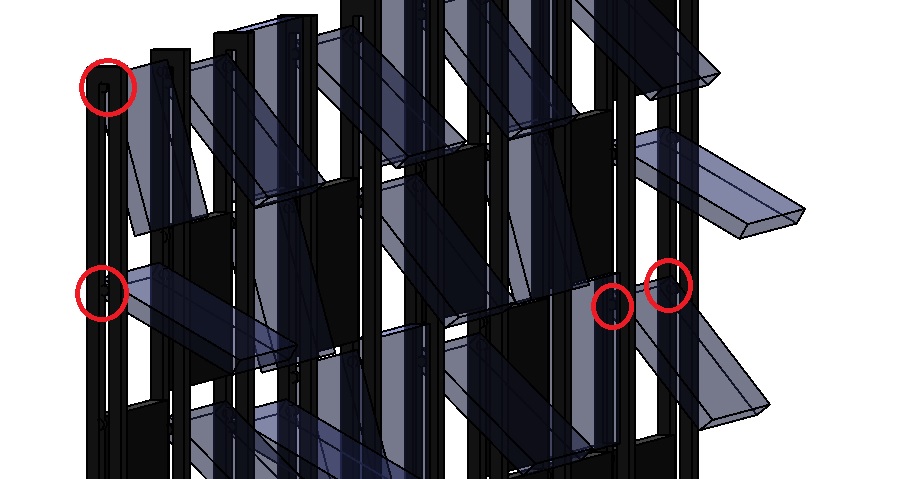
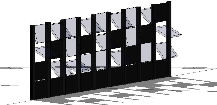
![]()


Now do the scheduling


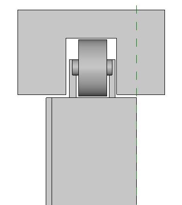
Are added, to finish, the nuts at the ends of the threaded bars and optimize the measures of the spacers for the construction (some really vary slightly)

 Matteo Molinari
Mer, 10/12/2014 - 20:24
Matteo Molinari
Mer, 10/12/2014 - 20:24
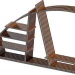
In this delivery we were asked to do a schedule of the parametric object used for the second one. The object I used is the cardboard made table shown in the headline image.
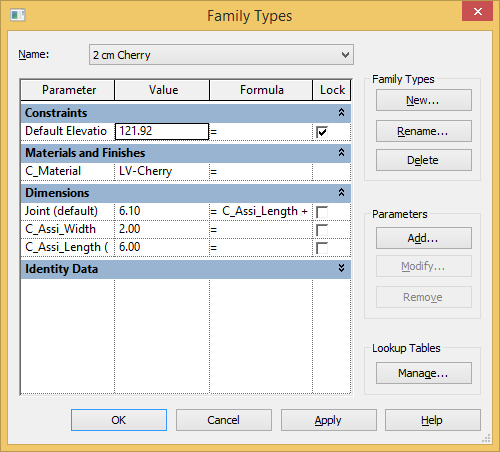
In order to do a schedule I had to change the parameters of every family that composed my old mother family. In the old families I had non-shared parameters, and in order to do a schedule I need shared-parameters. To do so I opened my old families and used the command PARAMETER PROPRIETIES this allowed me to create a SHARED PARAMETER sheet (f.1). The cool thing about this parameters is that they aren't just for one object but you can use it for every family you insert in your mother family. I created 2 shared parameters one is called "altezza" and the others "raggio"(f.2). This two parameters I think are enough to rapresent every object in my family. The main components of my table are cylinder so I think is right to use a ray and a height to parametrize them.
 f.1
f.1 f.2
f.2
Once I reasigned the shared parameters to every component of my table all is left to do is to reload every component in the mother family. I don't have to compone all over again the design I can just double click on the sub-family in the left side menu and use the command LOAD FAMILY, this way I substitute the old one with the new one.
Now I have to create a new project and load in it my table. To do so I used the commands NEW PROJECT, METRIC. (f.3) I renamed the project Schedule_Tavolo. To load the family in the project I had to open the mother family and used the command LOAD INTO PROJECT, a window will pop up and ask me in which project I want to load my mother-family. Now I have my mother family in my new projcet. (f.4)
 f.3
f.3
 f.4
f.4
Now it's time to make a schedule. The first thing to do is to reload the components of my table just to make sure that the shared parameters were all inserted in the project. Then i have to click on the command SCHEDULE.
A window wil open and ask me the type of schedule I want, I have to choose GENERIC MODEL. (f.5) Then I have to choose which proprierties I want to show up in my table. In this case I chose: Family, Family and Type, Altezza, Raggio. (f.6). Then I can pick the way I want my table to be ordered with the menu SORTING GROUPING. (f.7)
 f.5
f.5
 f.6
f.6
 f.7
f.7
I have just to press ok and my schedule is done. (f.8)

You can change the name of the schedule just by clicking beside VIEW NAME on the left side bar of the proprierties.
I wanted to insert the shared-parameter of the material, but I had problem once I imported it in the project, the material disappeared and the parameters won't show up.
Mer, 10/12/2014 - 20:55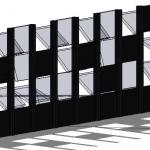 bleda oztek
Mer, 10/12/2014 - 13:44
bleda oztek
Mer, 10/12/2014 - 13:44
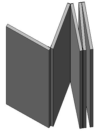
First of all I opened a family template in metric curtain wall panel and started to design my panel's carriers.
I created my reference lines and gave the measurments and added them as parameters saved them as instance
To insert the panels I emptied some space for it with void forms.
 Also I added parameters on the left side
Saved the family and loaded into new project template
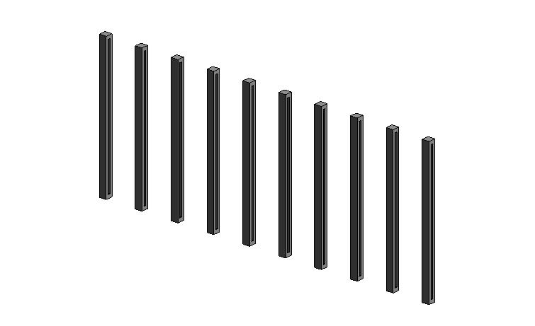
measured the distance of each carrier and placed them equally
I placed curtain wall panels between these carriers and divided them with grids
After that I opened a new family template in metric curtain wall based and started to design panels.
 I gave the reference lines first and drew panels
As you see on the picture there are two connecting pieces on panel which connects with carriers
After giving them names as parameter loaded them into project
I selected the piece I want and in properties changed as panel
But I wanted to create panels with different angles so I rotated them into different angles and saved all of them as family template
 I placed them into carriers and changed their materials in edit type.
Carriers and some panels are steel,and the other panels are glass.
Mer, 10/12/2014 - 14:54
 Irem Bahcelioglu
Mer, 10/12/2014 - 12:29
Irem Bahcelioglu
Mer, 10/12/2014 - 12:29
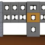
I tried to create accoridion facade. I created all the system parts.
I know that rolls shouldn't be as I did. They can turn 360 degree but I cannot imagine how I draw.
But I have a problem. When I loaded my panel into project, I met a problem. If they are straight, it is ok. But if they are folded, all the parts stand seperate. I cannot understand what I did wrong.
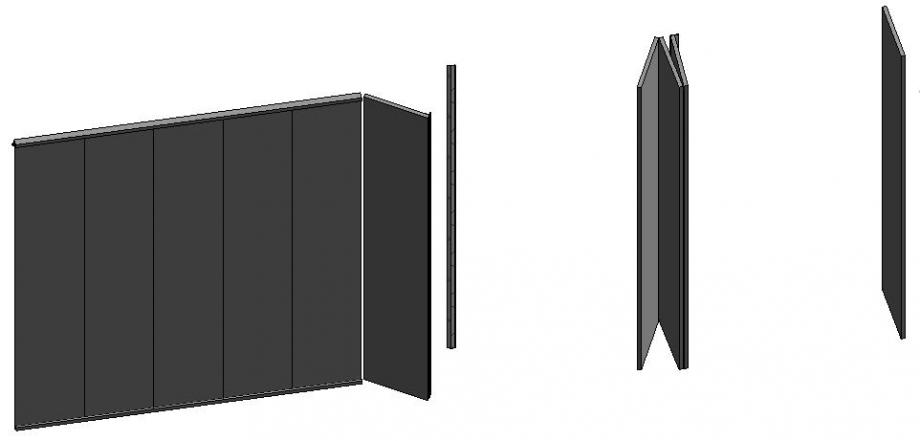
Also I tried to do another facade by using grids.
I did it how we did in the class. But I cannot change the material. Material parameters seem but when I apply them,they don't change.
 laura.vellucci
Mer, 10/12/2014 - 12:06
laura.vellucci
Mer, 10/12/2014 - 12:06
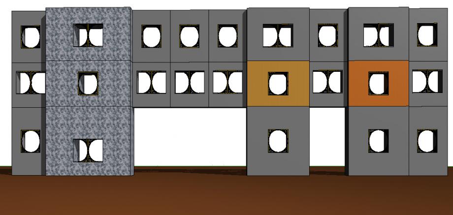
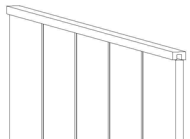
Create a family from template “Metric Curtain Wall Panel”
Do new family from template “Metric Curtain Wall Panel”
The template view is shown down (this is a mother family)
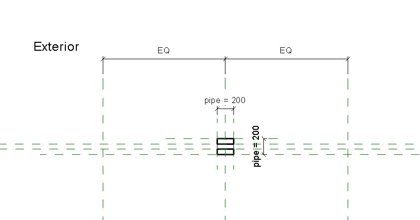
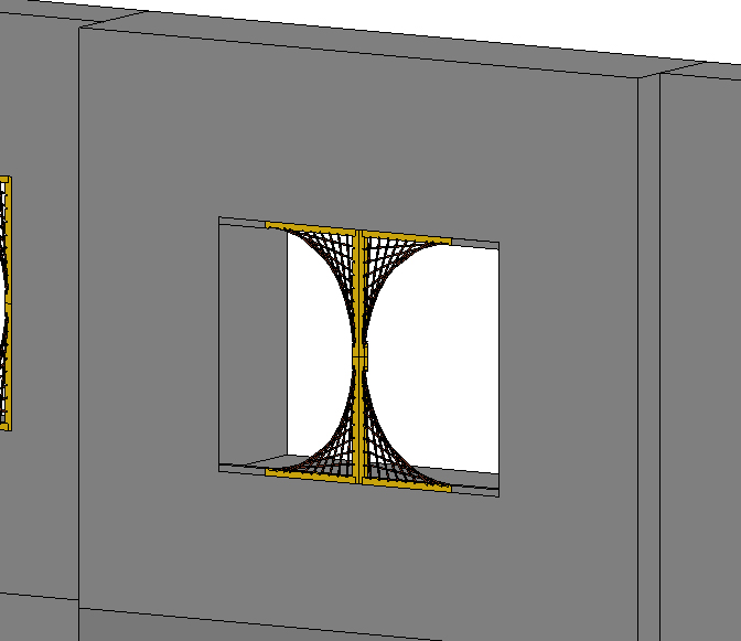
From the family “LV_dPattern” Create a new Family “LV_Assemble” from “Metric Generic Model” load it into the new mother family that named “LV_Curtain” and create an extrusion object as shown next:
Create Parameters “Width” and “Material”
Then create a new Project and Load the family into the Project.
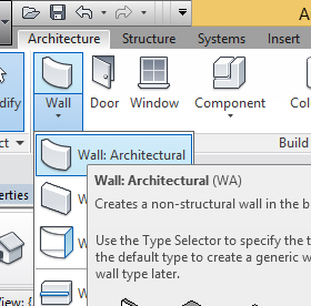
Click on Wall Icon and select “Wall: Architectural”
Click on “Type Properties”
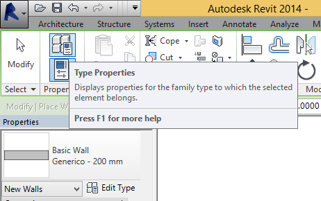
And select System Family: Curtain Wall
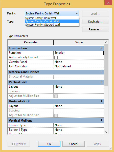
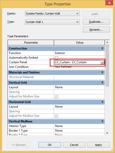
And now select the wall and in Curtain Panel select the family LV_Curtain
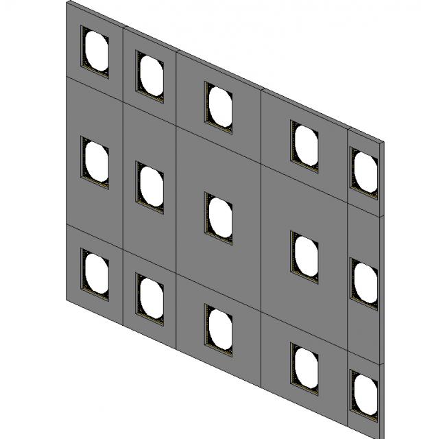
Draw the curtain wall.
Then do the grid for the curtain wall from menù “Architecture” - “ Grid Curtain”.
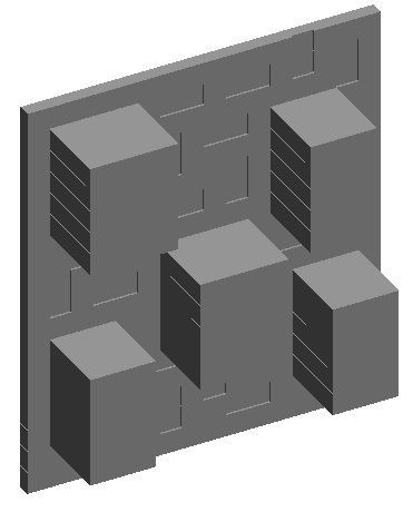
Obtain what is shown next:
Now select one part of the curtain wall with tab button and change "material" and "width" of some parts of the curtain wall. 
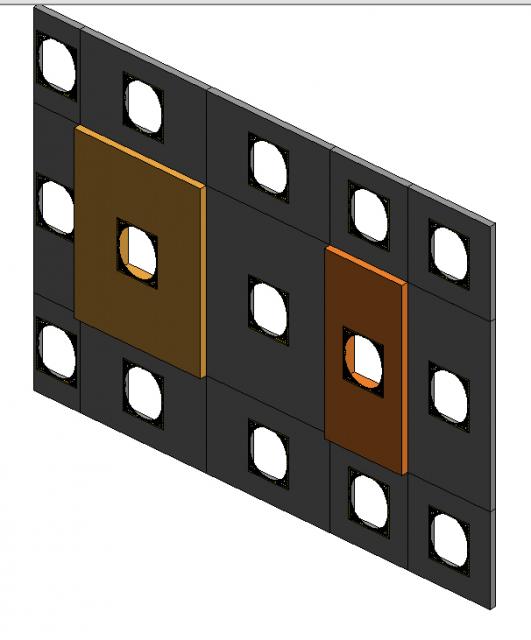
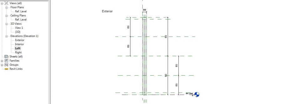
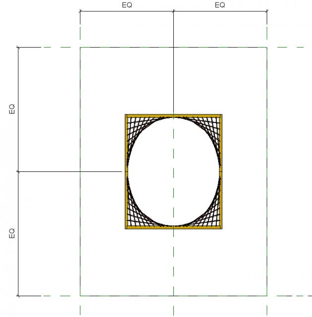
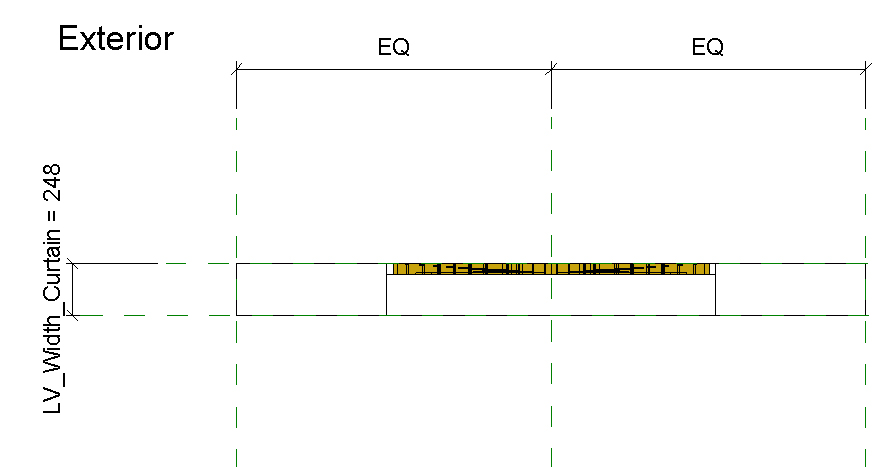
Try to change LV_Width_Curtain parameter in the family in the next way:
Then change the parameter “LV_Width_Curtain” = “LV_Lenght_Curtain”/5
Obtain what is shown down:
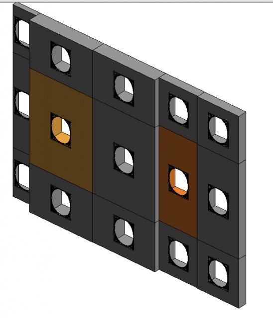
Create “LV_CurtainB” from family “LV_AssembeB”
Load into the project “LV_ProjectCurtain”
Then select a part of the curtain wall and click on the thumbtack to open it.
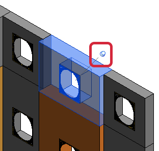
In Properties change the tipology of curtain wall and obtain what is shown next
Now plays to change some parts of the curtain wall