


 Vincenzo Panasiti
Ven, 19/12/2014 - 16:39
Ven, 19/12/2014 - 16:40
Vincenzo Panasiti
Ven, 19/12/2014 - 16:39
Ven, 19/12/2014 - 16:40 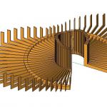 Felipe Figueroa
Gio, 18/12/2014 - 15:46
Felipe Figueroa
Gio, 18/12/2014 - 15:46
This is the consegna 2, where i wanted to add more modules to join the old ones, and add the material i choosed (wood).
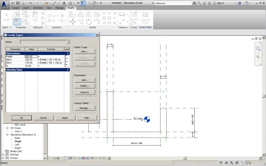
First i created a new family type with the same form, but more regular. Because i wanted the project to be of wood, so there are prefabricated modules.
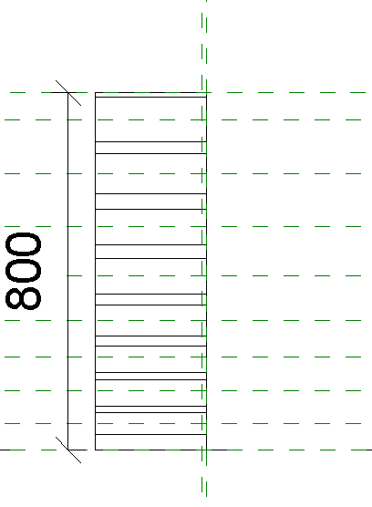
I used the same formula that depends on one parameter, the “pasillo” is the lenght of the corridor. Then “alto1” and “alto2” are the parameters that depends on “pasillo”.
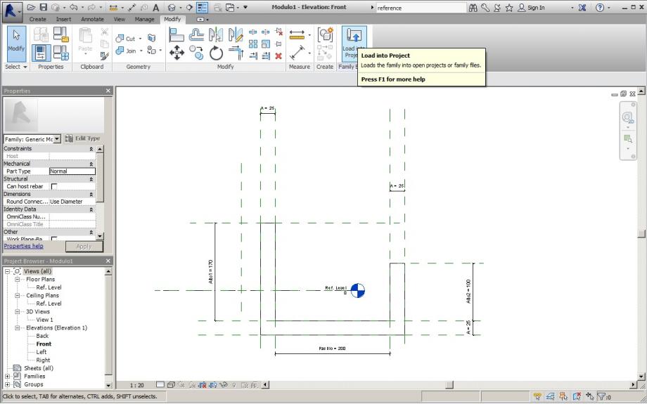
Then clicked “load into Project”.

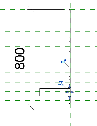
On this time i used a “reference line”, to help me keep the same distance to do de array with the other modules that i created forward.


Then used array, radial, 60 modules and a 5º of angle. This way the modules has enough space between, but also a good density.


After this i loaded into Project the other family that i created, a Little module that is for joining the first modules together.

Used the same array, with the same parameters.


Loaded other family, with another module for joining the first modules together.

Clicked "Place on Work Plane", this way the new elements are placed in the same plane of the first family.

Used the same array type, with the same parameters.

This way the "Stazione di Vedetta" has all the modules together, now its time to add the material.


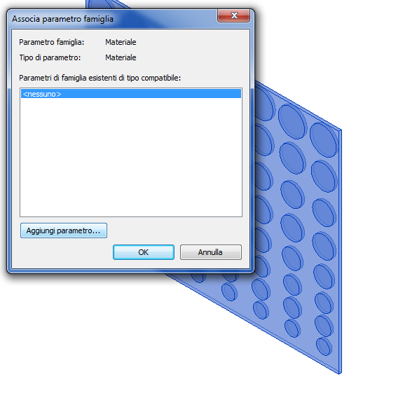
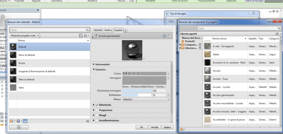
To add a material i choosed “associate family parameter” on the family type of the module.

This way i could create a new parameter with the material (texture) i wanted to use.

Choosed a Type parameter, and a family parameter.


Choose Softwood, Lumber and mark “adds this material to document”

Then i choosed load into project to refresh the family types on the main family.

Then i went module per module changing the parameter ("pasillo"), this way i was able to control the form and create two main permanence spaces, joined by a central corridor.


 andrea piattella
Gio, 18/12/2014 - 11:58
andrea piattella
Gio, 18/12/2014 - 11:58
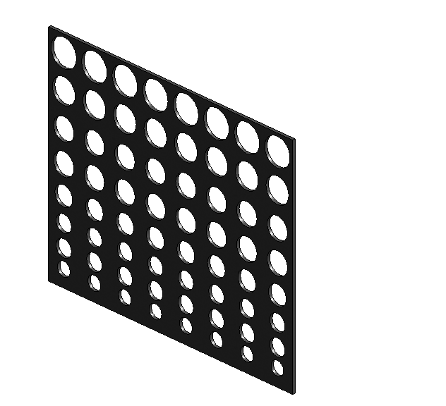
The first step to design the panel was creat a new family METRIC WALL PANEL (in this new family I created the component of the single panel of the future facade) - OPEN ( I saved this file and I gave to it a name).
I created the surface of the panel with the command REFERNCE LINE but be attentio tha you creat this surface in the front elevation
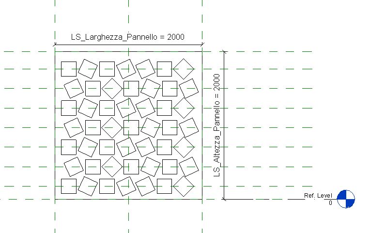
I assigned the dimension of the project
And I locked the surface to the reference line
After that I put on my panel surface the REFERENCE PLANES. These reference planes will be the guidelines of the holes that I want creat.
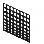
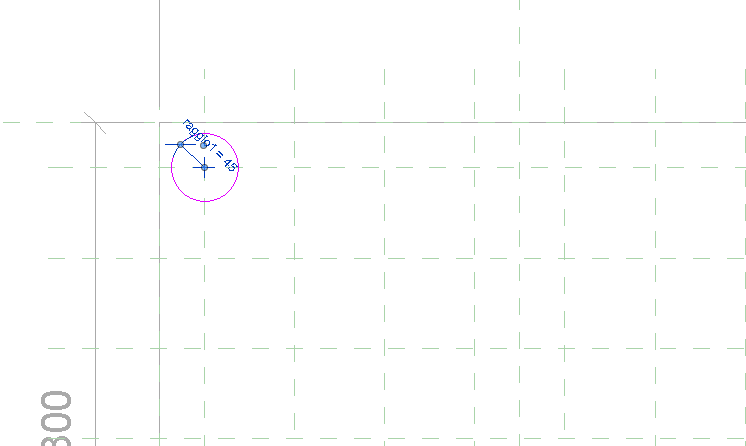
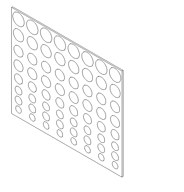
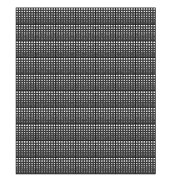
Than i draw the holes
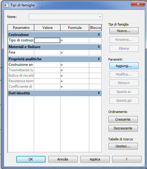
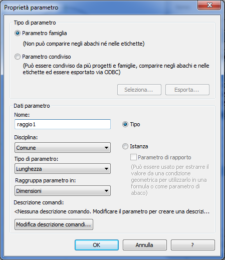
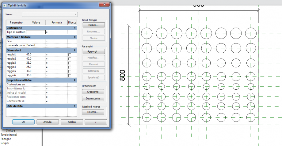
Now my target is assign to the holes parameters that allow me to control their dimension, diameter or form. I assigned different parameters to the holes if I will change them in different way. FAMILY TYPES - ADD...
Finished the front elevation I change View and I selected the side view to assign the width to the metal plate.
To assign at the objet the material I selected it and assigned a new parameter to the family.
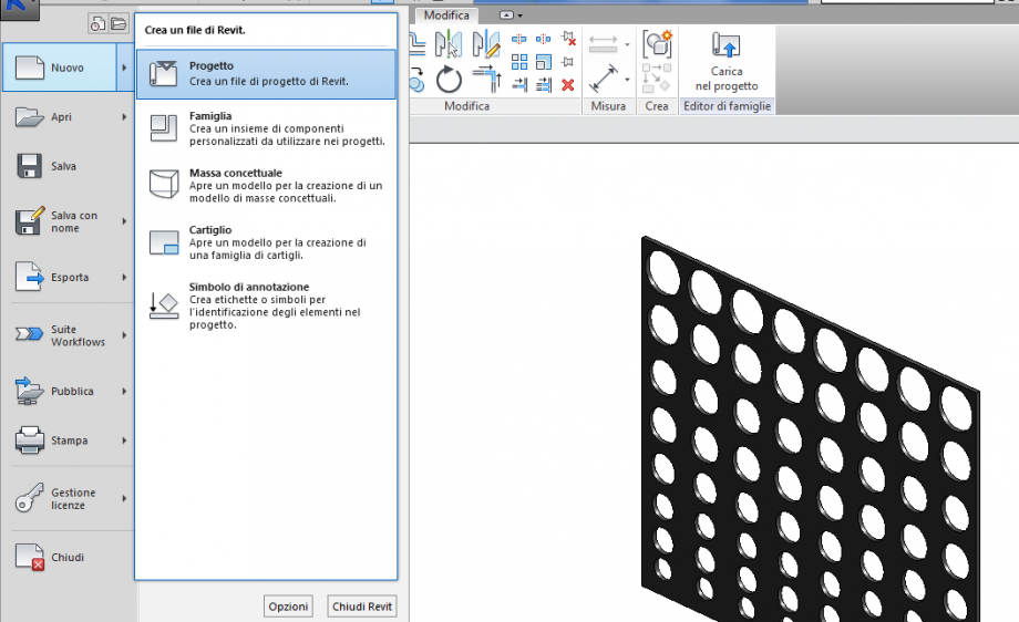
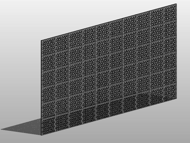
Now we face the second step to creat a Curtain Wall. I opened a new project. Inside it I will upload the panel to create the curtain wall. FILE- NEW - PROJECT
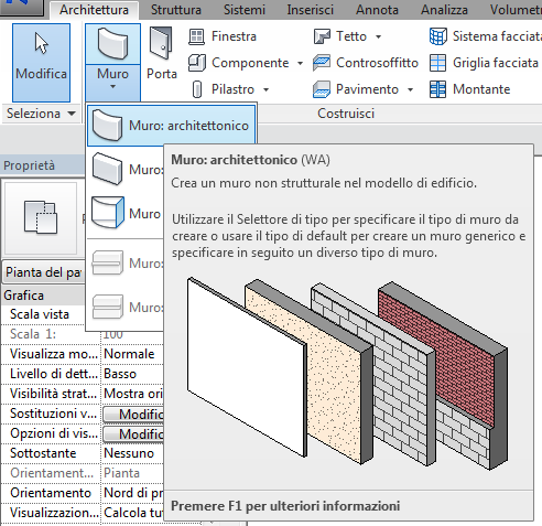
With the command WALL I created an architectural wall. I design initially the wall in the floor view and than I edited it.
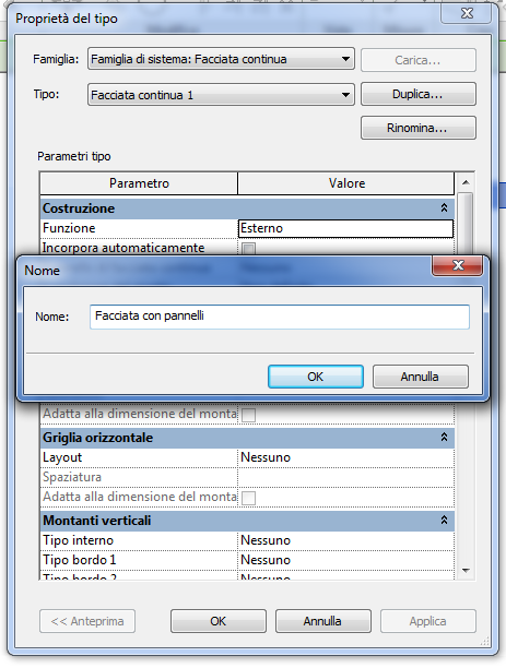
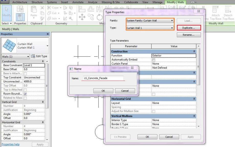
In the properties tab I clicked EDIT TYPE - SYSTEM FAMILY(curtain wall) - DUPLICAT and renamed the family - OK
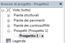
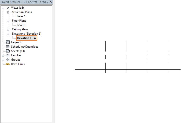
I created a new view and I chose it VIEW - ELEVATION - PROJECT BROWSER - ELEVATION
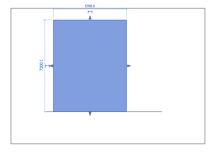
Now I can assign the correct dimension of the wall.
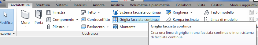
To position every panel on that wall I draw a grid that will be the location of the panel - ARCHITECTURE - CURTAIN GRID
this grid have to have the same dimension of the pannel created before.
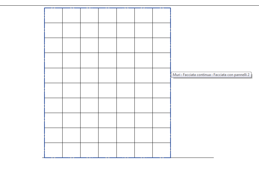
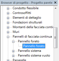
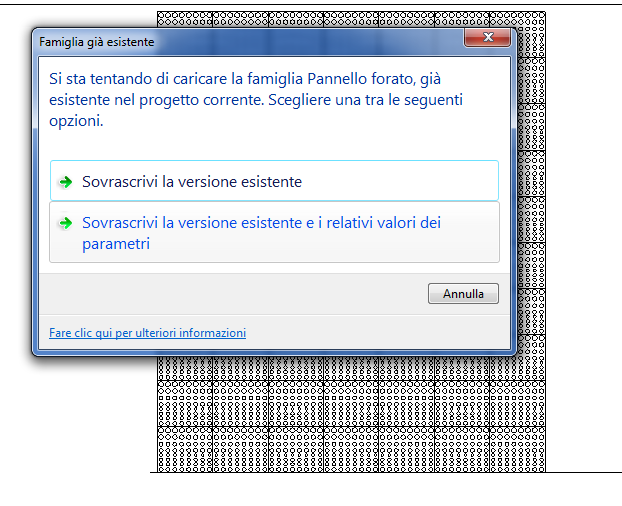
Once I finished the grid I loaded into the project the panel. After that I find it in the project browser - curtain panels - perforated panel
To import the panel in the curtain wall I have to set (in the curtain wall type properties) the panel designed before as the panel for the curtain wall.
Now if I wanto to change the dimension of the holes and the disposition of them I have just to modify the parameters in the family of the panel and reload it again in the project.
Gio, 18/12/2014 - 13:39
 StefanoConverso
Gio, 18/12/2014 - 16:00
StefanoConverso
Gio, 18/12/2014 - 16:00
Ecco i video della Lezione:
Prima parte:
Seconda parte:
cari ragazzi,
la lezione di domani, 18 Dicembre 2014
è quella in cui presenteremo il Tema d'anno.
E' pertanto ESTREMAMENTE importante che tutti gli studenti garantiscano la loro presenza, e portino anche un proprio portatile con il software installato. Per partecipare al tema d'anno, infatti, dovremo collegare tutti i partecipanti a un modello in rete, e lavoreremo sui computer di ognuno per configurarli. Spargete la voce a tutti. A domani, inizio ore 16.
Stefano Converso
--
mediaimage courtesy of Alienlog
Alcuni passaggi per prepararsi al lavoro in aula:
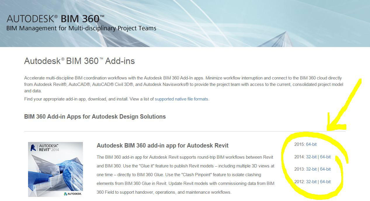
- collegarsi al sito di Autodesk BIM e scaricare i plugin per revit:
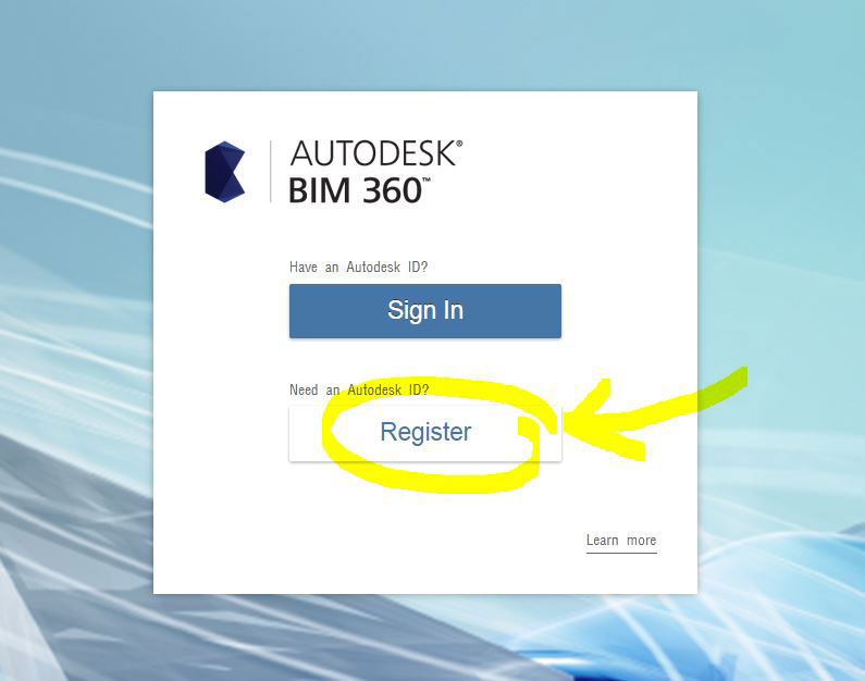
- Munirsi di un account Autodesk, collegarsi al sito Autodesk BIM 360 Glue e immettere i dati del vostro account autodesk se già lo avete:
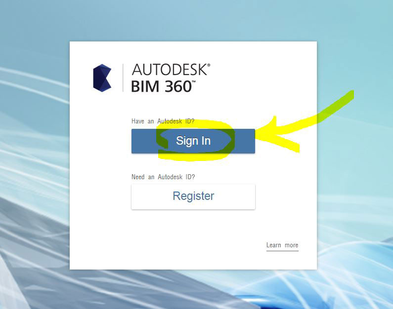
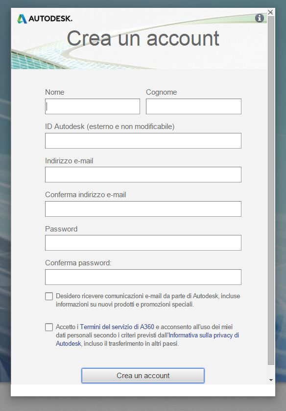
oppure registrarsi cliccando su "Register" e compilando il registration form:
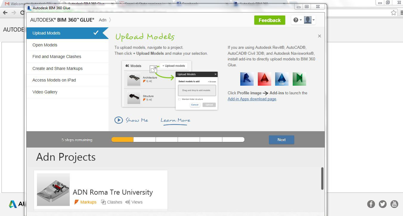
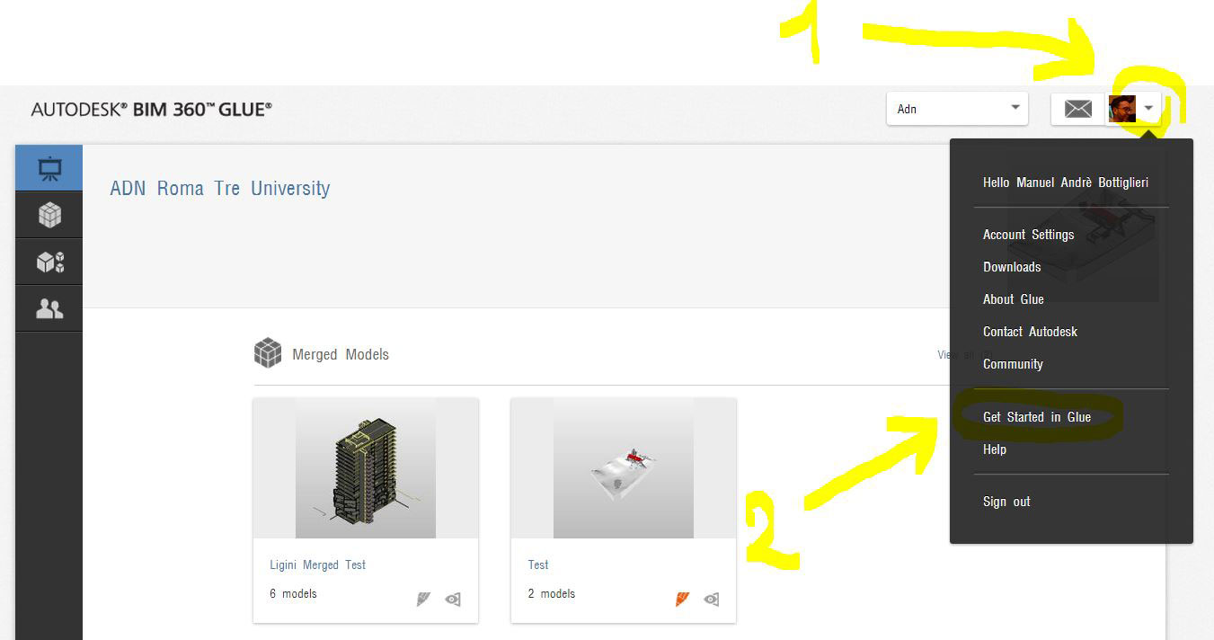
- dopo aver effettuato l'accesso vi comparirà questa schermata:
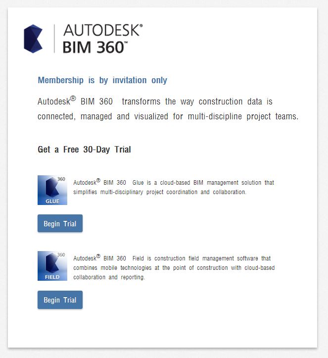
- è tutto normale! nessun errore. A questo punto siete pronti per domani, durante la lezione manderemo ad ognuno di voi l'invito per far parte del programma.
- Di seguito un esempio di invito che manderemo domani alle vostre email:
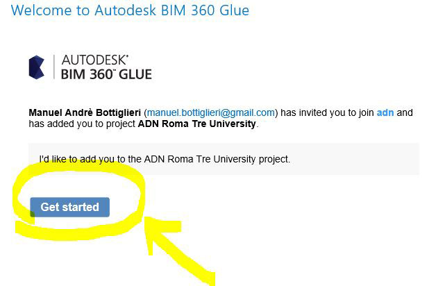
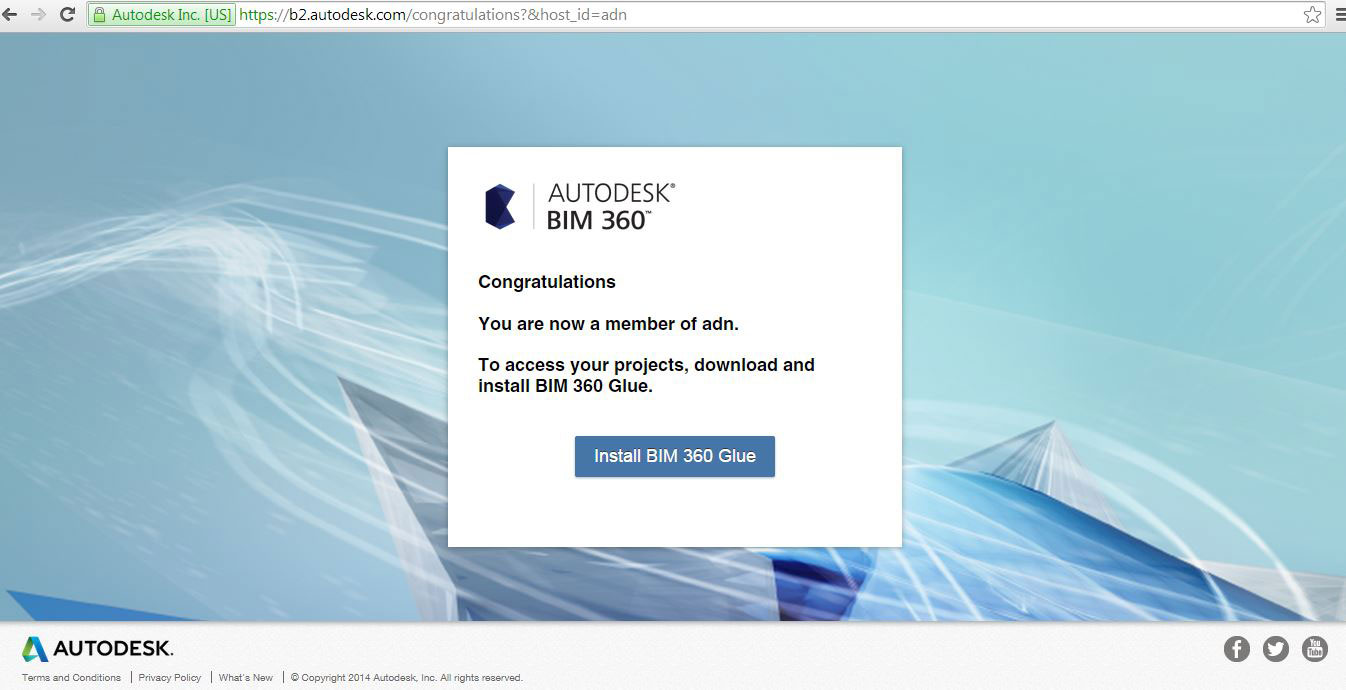
- l'invito vi indirizzerà alla pagina web di BIM 360 Glue dove metterete i vostri dati di account autodesk per il login. Ed ecco entrati nella community adn:
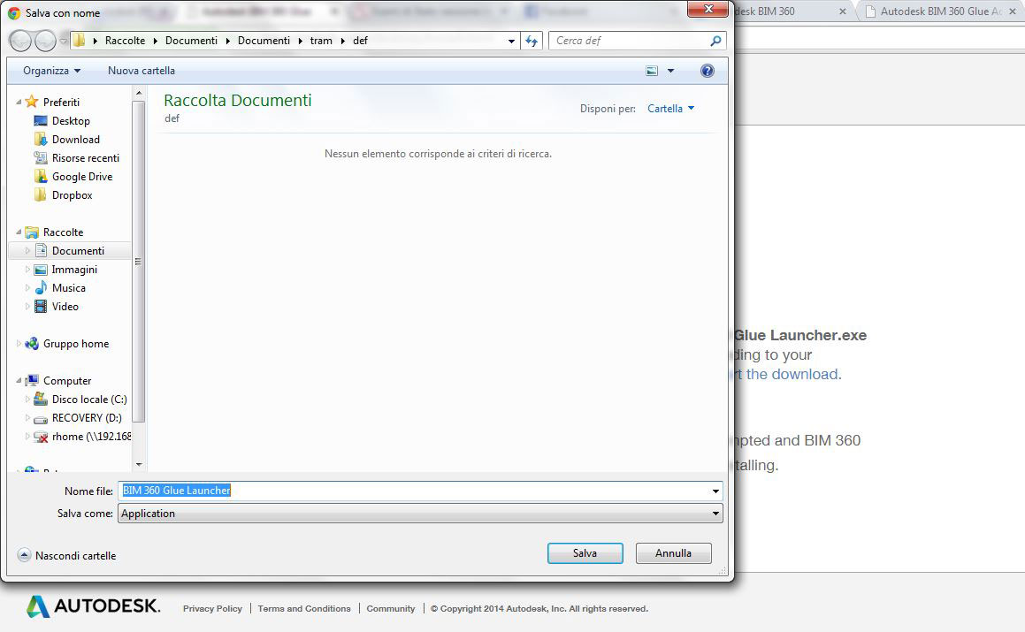
- una volta entrati avrete il link per installare il software BIM 360 Glue; ecco i passi da seguire per l'installazione:
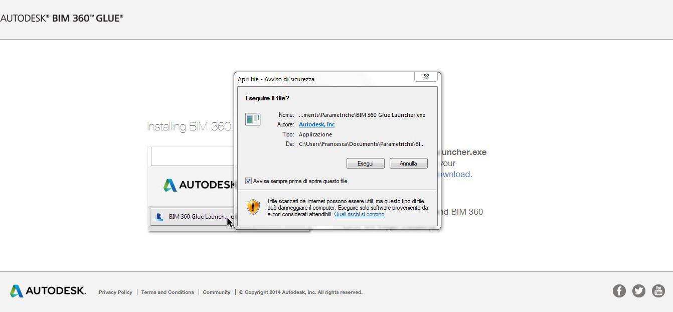
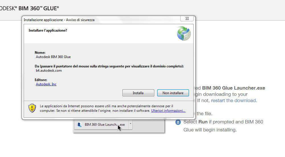
- ovviamente click su installa...
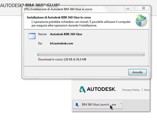
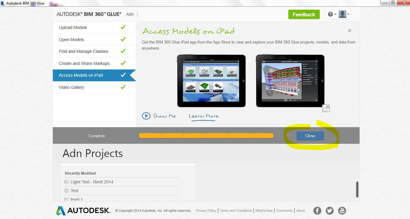
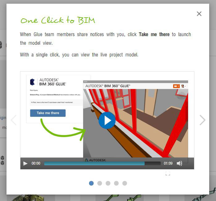
- attendete che l'installazione sia completa e poi vi si aprirà questa pagina:
- chiudete la finestra informativa, e siete dentro Glue!
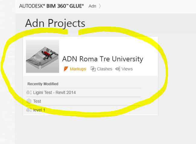
- da qui potrete entrare nel progetto condiviso, cliccando sulla finestra ADN Roma Tre University
- dopo l'accesso alla pagina web di Glue se avete tempo cominciate a dare un occhiata ai video getting started:
- questo è il link per scaricare i modelli : File 1, File 2
a domani con.....
 Lodovica Silva
Mar, 16/12/2014 - 20:03
Lodovica Silva
Mar, 16/12/2014 - 20:03
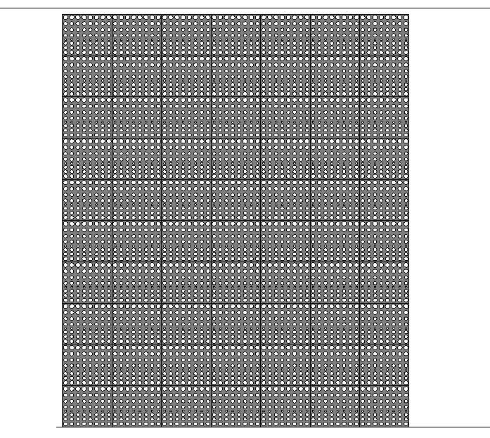
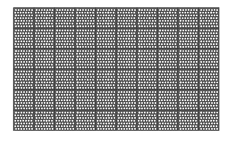
Per questa consegna è stato creato un COMPONENTE DI FACCIATA. Vediamo come:
For this delivery, it was created a FACADE COMPONENT. Let's see how:
1_IL COMPONENTE (COMPONENT)
- Pannello - The Panel
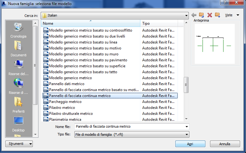
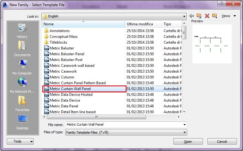
Apro una nuova Famiglia>METRIC CURTAIN WALL PANEL,
I Create a new Family>METRIC CURTAIN WALL PANEL,
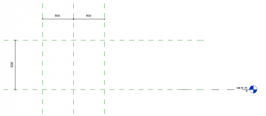
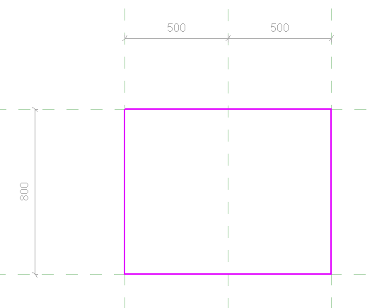
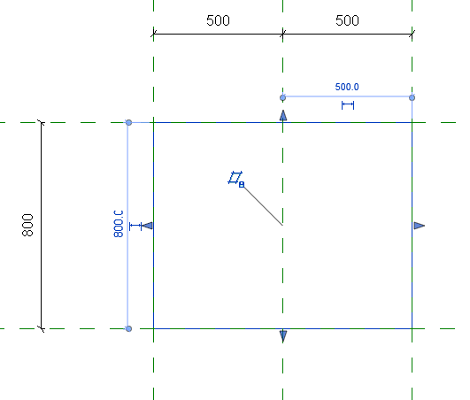
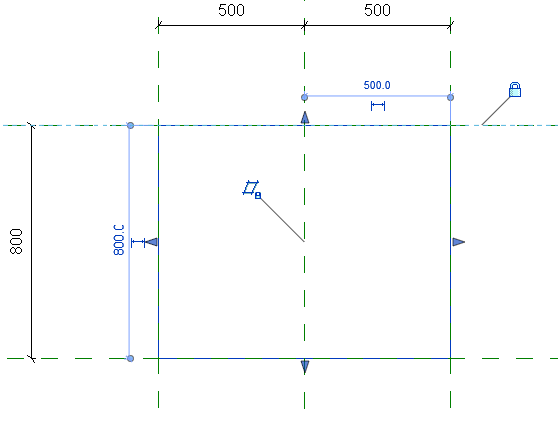
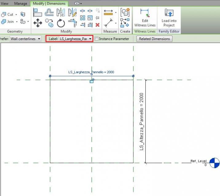
Nella vista Exterior, attribuisco una quota ai REFERENCE PLANES che ho di default attraverso il comando Modify>Measure>ALIGNED DIMENSION, dopodiché seleziono le quote e le parametrizzo cliccando su Label>ADD PARAMETER.Ora creo un'estrusione selezionando Create>Extrusion>Draw>RECTANGLE e, a questo punto, lego la geometria ai parametri attraverso Modify|Create Extrusion>Align o digitando sulla tastiera AL e selezionando prima il REFERENCE PLANE poi il lato da allineare e lucchettare.
In the Exterior view, I quote the REFERENCE PLANES through the command Modify>Measure>ALIGNED DIMENSION, then I select the units and I give it a parameter clicking Label>ADD PARAMETER. Now I create an extrusion by selecting Create>Extrusion>Draw>RECTANGLE and add parameters by Modify|Create Extrusion>Align or typing AL on the keyboard and selecting first the REFERENCE PLANE then the side to align and lock.
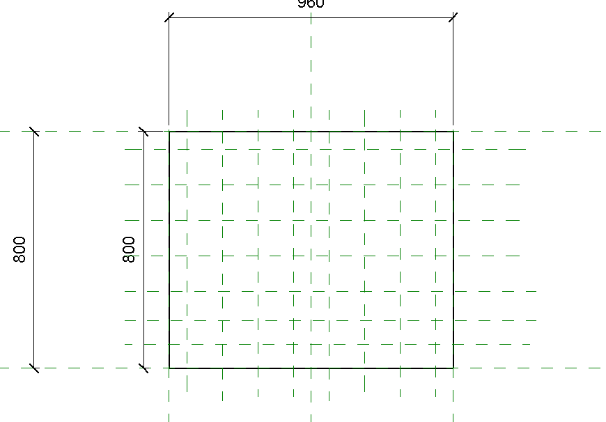
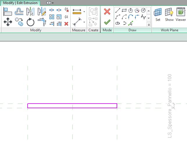
Posizionandomi nella vista FLOOR PLANS, ripeto l'operazione attribuendo uno spessore al mio pannello.
In FLOOR PLANS view, I repeat the operation by assigning a thickness to the panel.
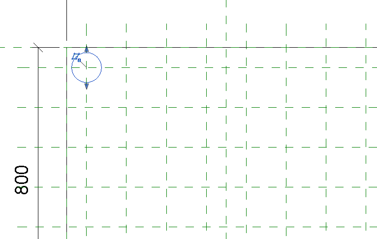
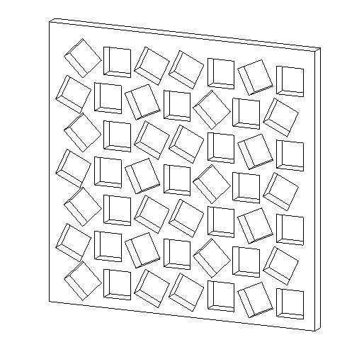
A questo punto, tornando sulla vista Elevations>Exterior,mi creo dei Reference Planes e, selezionando il pannello, compare sulla barra degli strumenti il comando EDIT EXTRUSION, che mi permette di disegnare delle bucature.
Now, back on the Elevations>Exterior view, I create Reference Planes and, selecting the panel, I can click on the toolbar command EDIT EXTRUSION, which allows me to draw the openings.
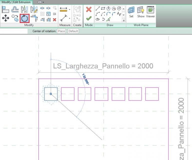
Do alle bucature 4 diverse INCLINAZIONI (25°,45°,65°,90°) attraverso il comando Modify | Edit Extrusion,
I give 4 different INCLINATIONS ( 25 °, 45 °, 65 °, 90°) to the openings throught the command Modify | Edit Extrusion,
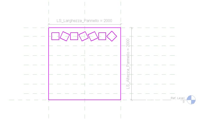
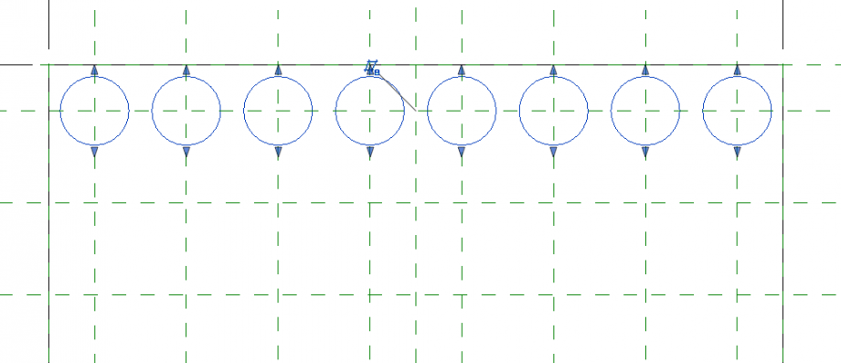
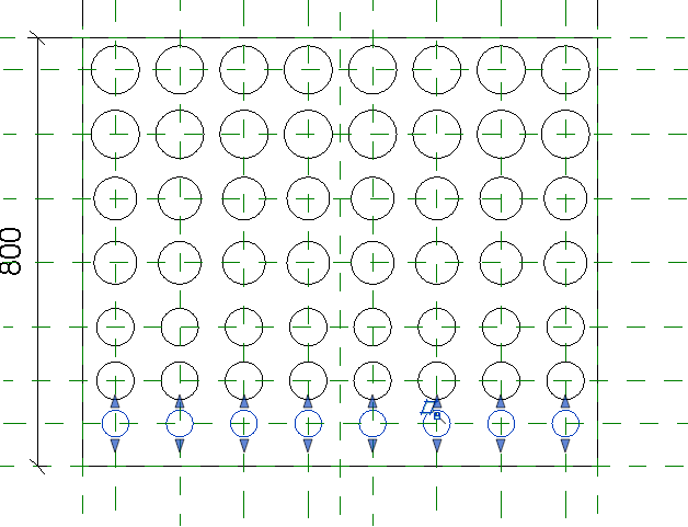
Quindi copio la serie e la ricopio facendo riferimento ai Ref. Planes.
Then I copy and insert the series along the axis of the Ref. Planes.
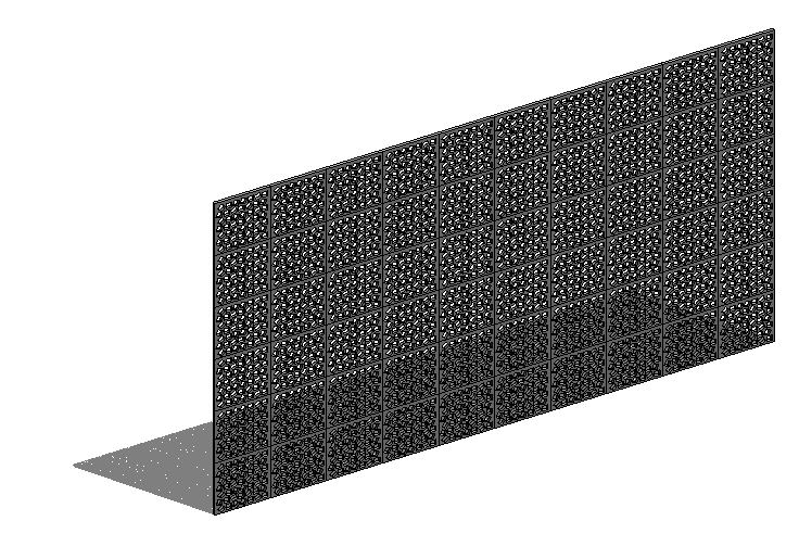
Ora posso inserire il pannello nel mio sistema di facciata, ma prima devo creare una WALL sulla quale applicare il pannello.
Now I can put the panel in my facade system, but first I have to create a WALL on which I've to insert the panel.
2_IL PROGETTO (THE PROJECT)
- Facciata - Architectural Wall
Apro un nuovo file di progetto New>Project>Template file>none>metric. Creo una facciata attraverso il comando Architecture>Wall> WALL:ARCHITECTURAL, dopodiché creo una nuova vista View>Elevation>ELEVATION e la oriento attraverso il tasto TAB (ruota il punto di vista).
I open a new project file New>Project>Template file>none>metric. I create a facade clicking Architecture>Wall>WALL: ARCHITECTURAL, then Icreate a new View>Elevation>ELEVATION and rotate the view through the TAB key.
A sinistra su Properties>EDIT TYPES definisco la mia facciata cliccando su Duplicate.
On Properties>EDIT TYPES to the left side, I define my facade by clicking on Duplicate and naming the type.
Do al muro le dimensioni che mi servono, e, dopo averle selezionate, le imposto attraverso Properties>Edit Type>Duplicate>UNITS FORMAT.
I give the wall the dimensions needed and, then I select the quotes to edit through Properties>Edit Type>Duplicate>UNITS FORMAT.
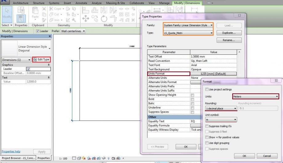
Per attribuire le stesse impostazioni alle altre quote, clicco su Modify | Dimension>Clipboard>Match type properties. Attribuisco una griglia alla facciata attraverso Architecture>CURTAIN GRID, per poi impostare il pannello attraverso Edit Types>Curtain Panel.
I click on Modify | Dimension>Clipboard>Match type properties to assign the same properties to the other units. I create a grid through the command Architecture>CURTAIN GRID, then I set the panel clicking Edit Types>Curtain Panel.
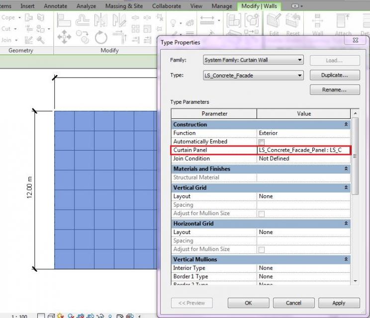
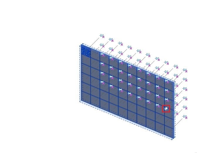
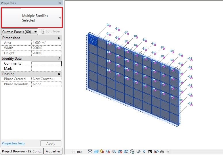
Non mi resta che inserire il pannello nel progetto, prima attraverso LOAD INTO PROJECT, poi selezionando la facciata, sbloccando i PIN e selezionando il pannello nel menù a tendina delle Properties.
I just have to put the panel in the project, first through LOAD INTO PROJECT, then selecting the facade, unlocking the PIN and selecting the panel in the Properties dropdown menu.
Mar, 16/12/2014 - 21:54