 MARIA IURESCIA
Ven, 02/01/2015 - 16:30
MARIA IURESCIA
Ven, 02/01/2015 - 16:30
Salve,
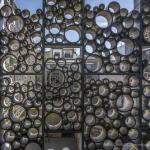
per il tema della facciata ho preso spunto della facciata del museo della ceramica di Triana; quello che mi colpisce è come i progettisti sono riusciti a riutilizzare un elemento molto semplice, il tubo in terracotta e/o ceramica, applicandolo in facciata e ad avere così diversi benefici per l'edificio stesso: primo tra tutti un controllo dell'ombreggiamento delle facciate molto attento in relazione alla posizione e alla profondità che viene data a questi elementi.
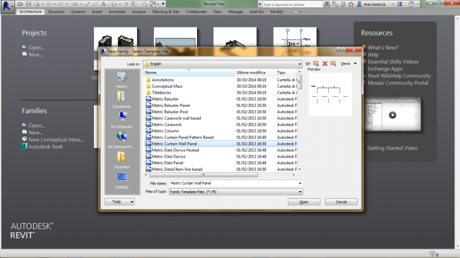
Pensando in termici pratici nel trasferimento del riferimento in un progetto ho pensato di crearmi i diversi tubi di ceramica, con i diversi diametri, aprendo new family>metric curtain wall panel.
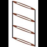
Ho creato quindi i diversi tubi:
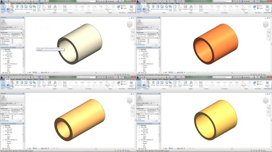 Dopo aver creato i diversi profili la mia idea è quella di creare il telaio di facciata su cui assemblare i diversi elementi...
Grazie ad una consegna ho avuto qualche dritta...
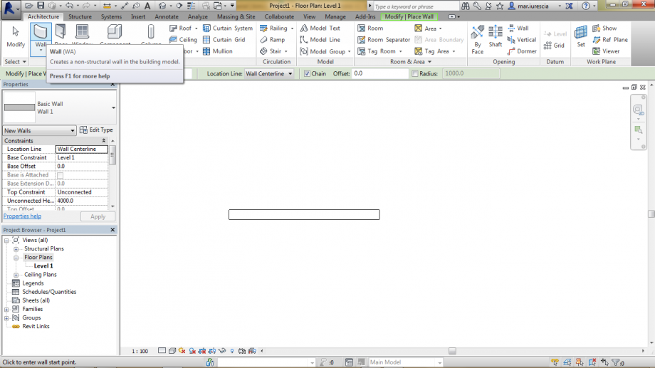
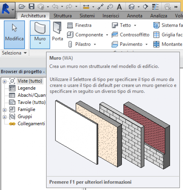
Ho aperto un nuovo file Project>metric, ho selezionato
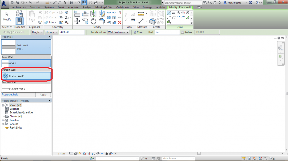
e con il comando griglia volevo disegnare il mio telaio. Ho quindi disegnato la lunghezza del mio "muro" e con il comando curtain grid pensavo di riuscire a disegnare il mio telaio ma non ci sono riuscita...
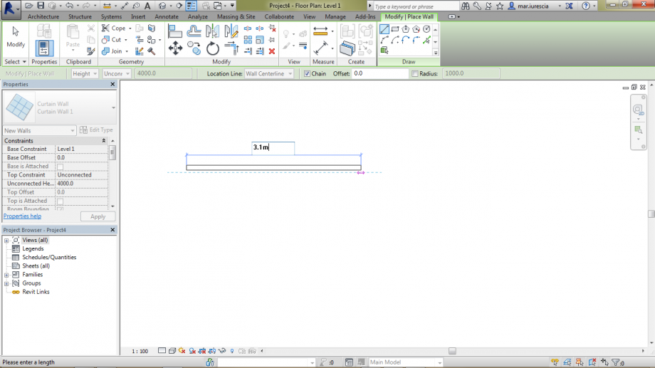
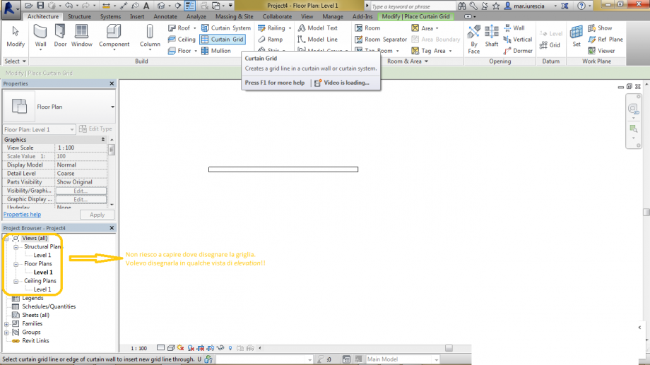
Probabilmente non riesco a capire qualcosa, oppure avrò visto male il video della lezione...
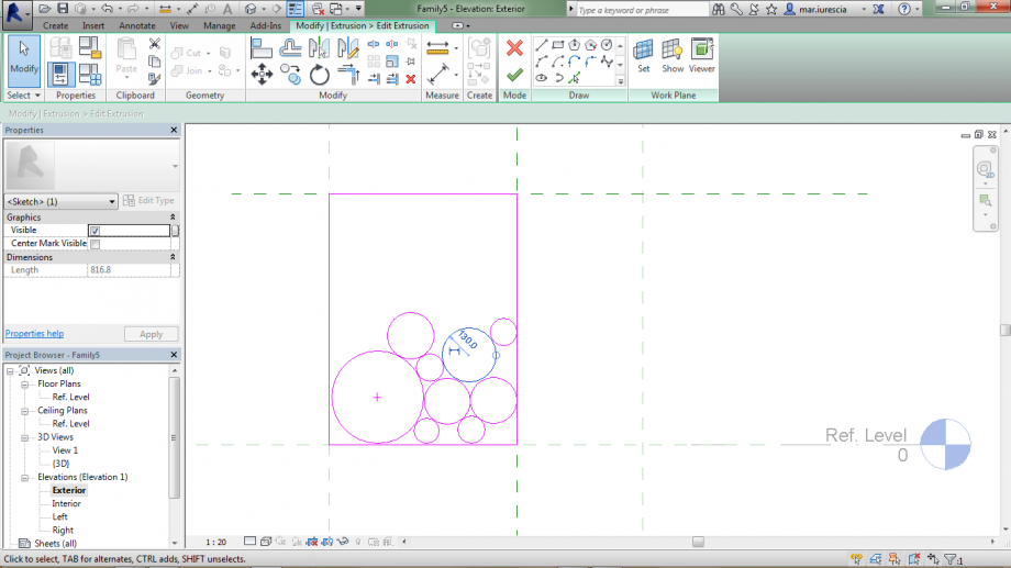
Ora provo creando un pannello...
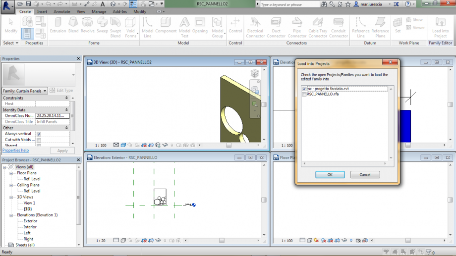
Apro revit: new>family>metric curtain wall panel; estrudo il mio pannello assegnandogli anche il materiale:
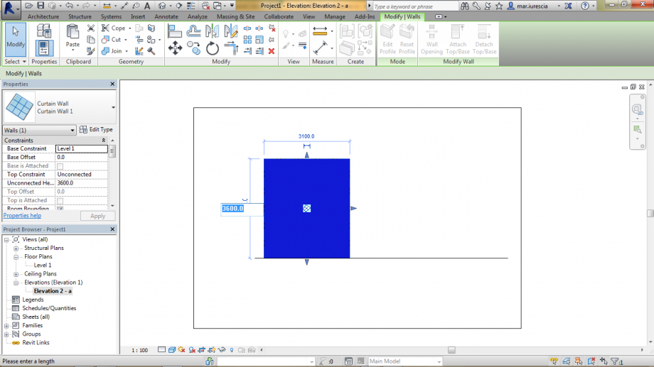
Sono quindi passata nell'ambiente di progetto dove ho aperto un nuovo file Project> nome> metric. In architecture ho scelto wall e nella finestra di proprietà curtain wall quindi nella vista floor plan ho disegnato il mio muro:

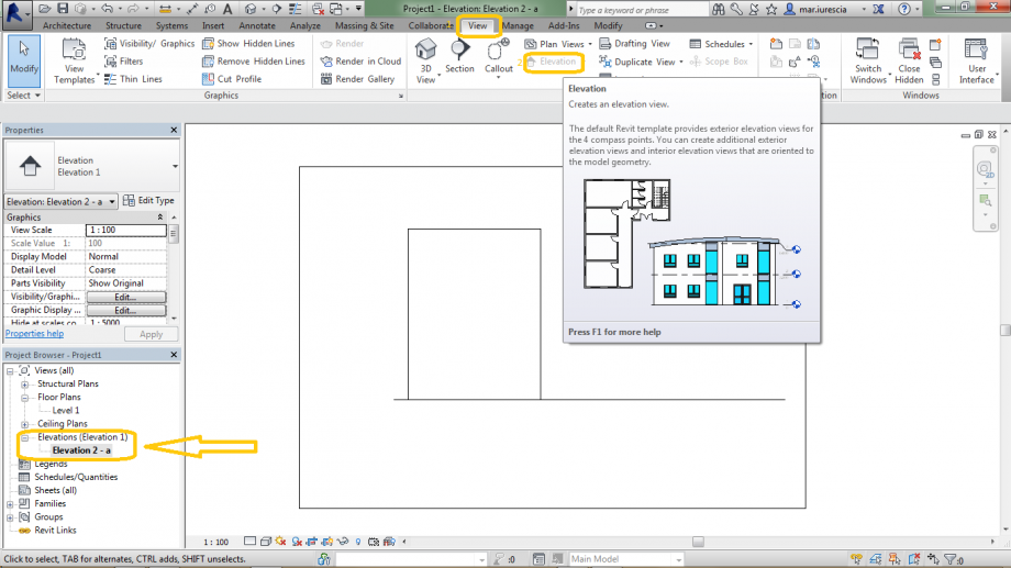
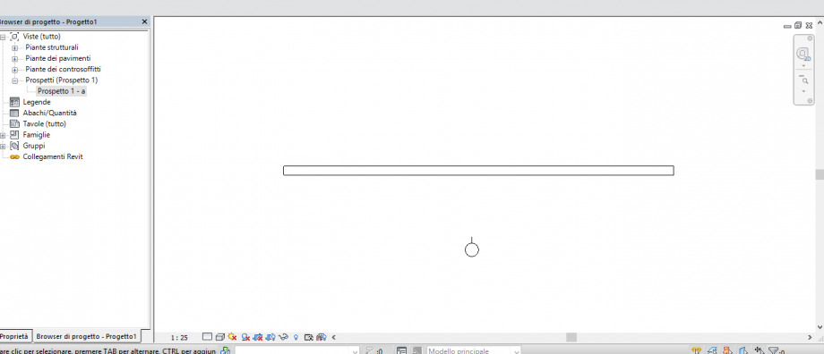
Quindi mi sono creata una nuova vista di prospetto poichè non è presente di default, per fare questo sono andata nel campo view> elevation; ho quindi definito il campo di visuale:
selezionando lo stile di vista shaded ecco che il muro appare colorato di blu:
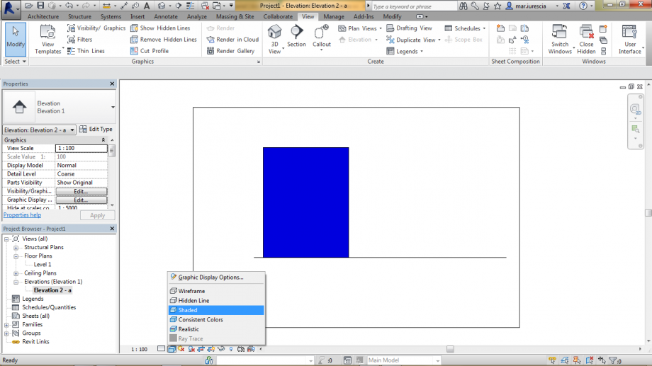
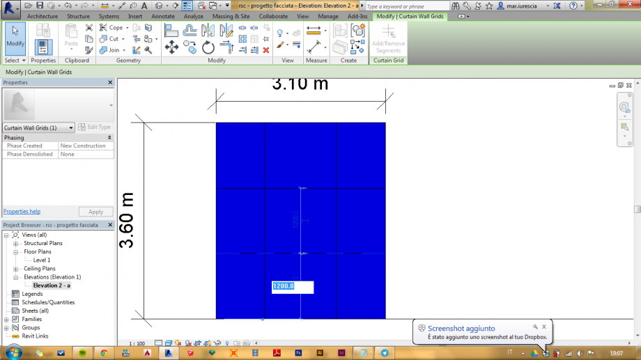
in questa modalità è più visibile il muro e quindi manualmente procedo a modificare la dimensione del muro ed aggiusto l'estensione delle quote:
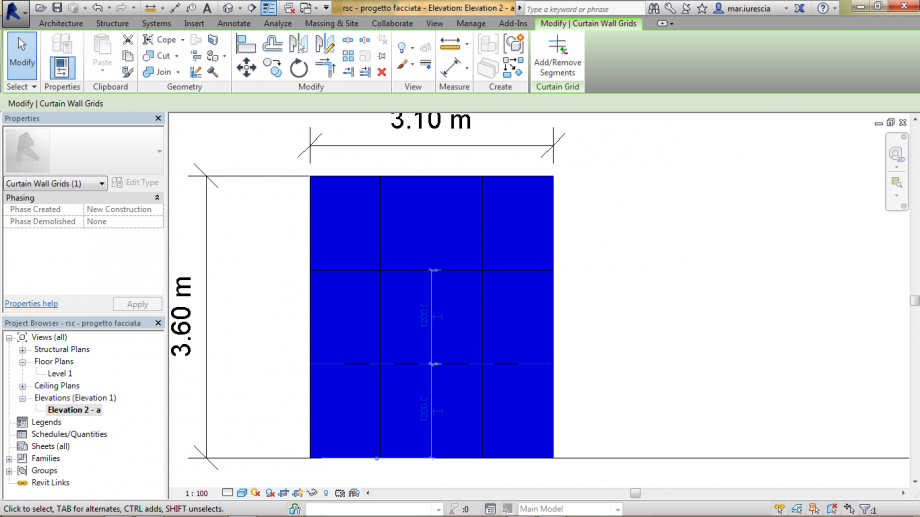
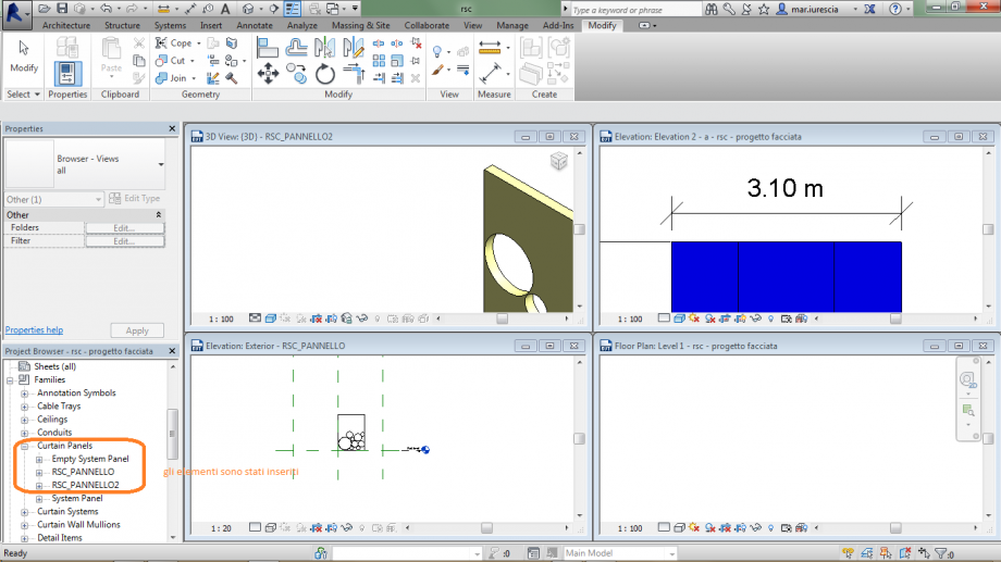
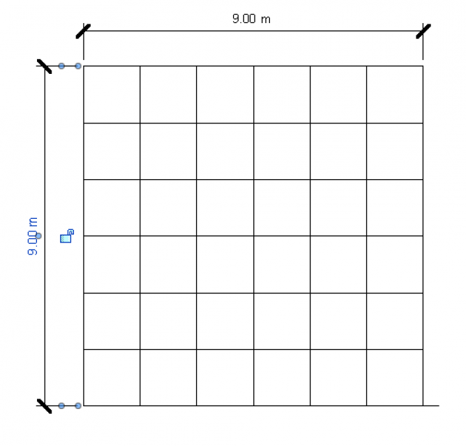
nel campo architecture> curtain grid; ho disegnato la griglia per l'ancoraggio dei pannelli, che per esser inseriti devono essere caricati nel file di progetto:
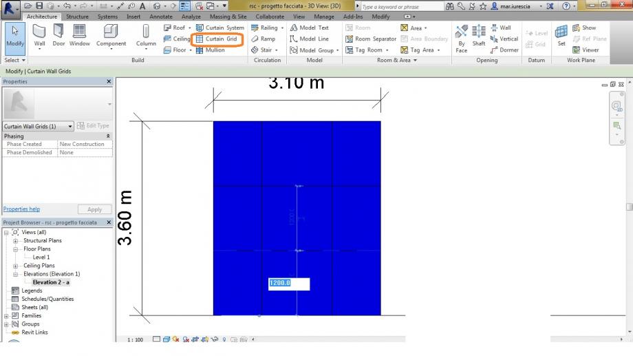
è possibile anche una volta disegnata modificare la griglia cliccando su di essa:
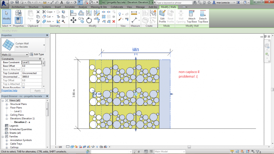
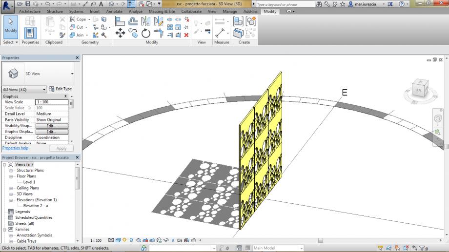
ecco l'effetto di ombreggiamento che si ottiene in questo modo... é un pò diverso dalla mia idea iniziale ma continuerò a lavorare anche sulla precedente cercando di andare avanti lì dove mi sono fermata.
Buon anno appena iniziato!
Ven, 02/01/2015 - 16:50
 laura.vellucci
Ven, 02/01/2015 - 16:00
laura.vellucci
Ven, 02/01/2015 - 16:00
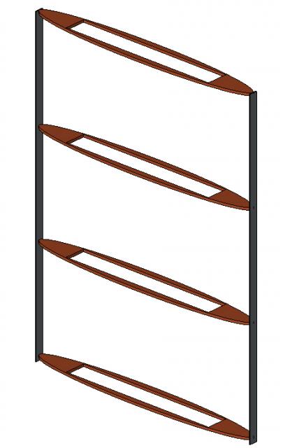
Array Curtain Wall Panel
Create a new family from "Generic Metric Model" and do a simple parallelepiped and load it in another family created from template “Metric Curtain Wall Panel”
Create the parameter for the Length and trasform it in a reporting parameter as shown below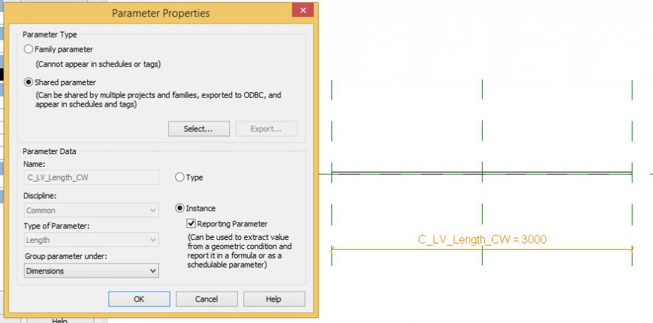
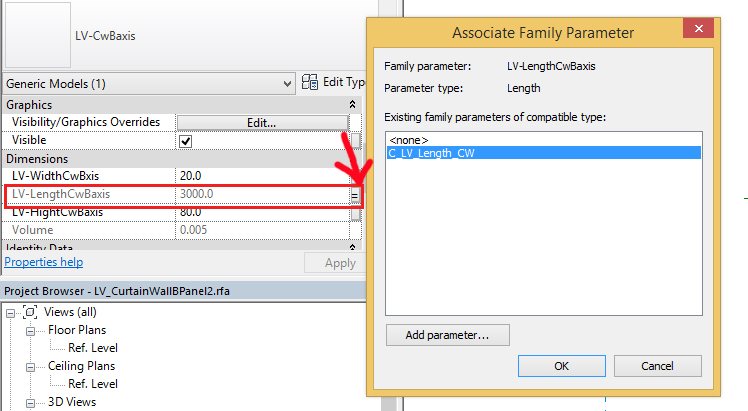
Modify the parameter that describe the length of the axis and associate it with the parameter C_LV_Length_CW
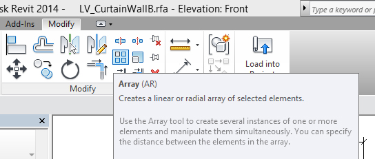
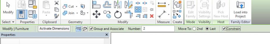
Do an Array from menù Modify
Select the axis that you loaded to do the element of array and click on return then set up the Array value and click first point and the last point.
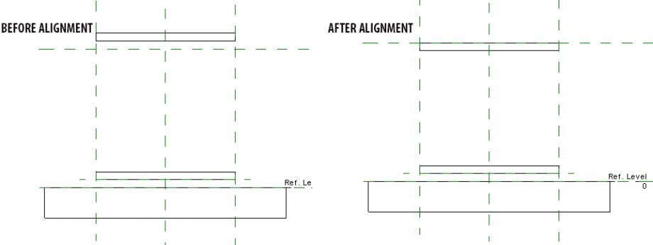
Line up the last axis at the reference plane that indicate the hight.
Create a parameter to define the number of axes into the array.
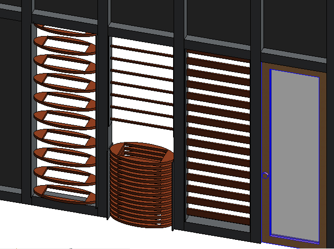
Now load this family in a project with a curtain wall. Notice that you can change the number of the element Array.
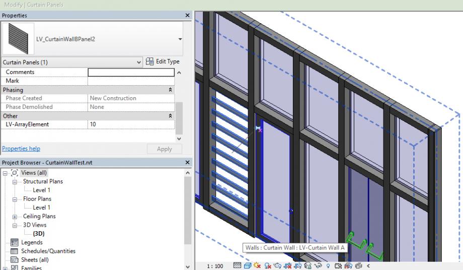
Only changing the initial element you can obtain another curtain wall panel.
Ven, 02/01/2015 - 16:16
 laura.vellucci
Sab, 27/12/2014 - 19:19
laura.vellucci
Sab, 27/12/2014 - 19:19
Create a new family from template “Metric Door – Curtain Wall”
Do reference planes to create the frame of the door in Ref. Level and in the Exterior view.
Create the parameter “LV-Door-CW” and do the extrusion to create the frame.
Now do the door panel and create 2 parameter “LV-frameWidth” and “LV-DoorWidth” (always with reference planes).
Create the handle and the material parameter.

Create 3 types: dark wood, light wood and metal for the frame and leave like an istance parameter the panel material)
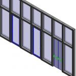
Now do a new project
Create a new architectural wall and select Curtain Wall

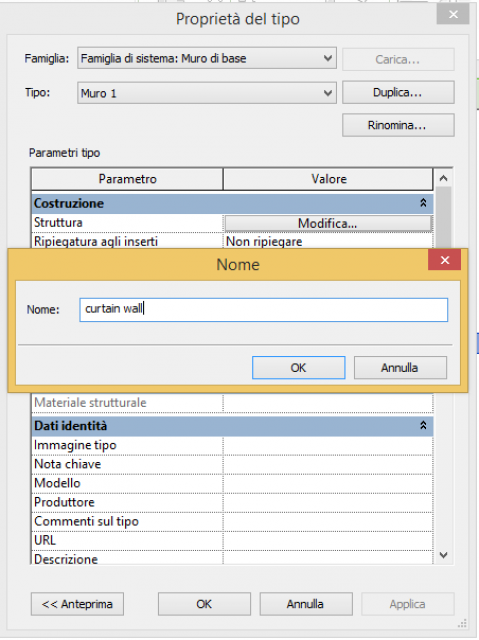
click on type properties and Duplicate and Change name to the wall and push ok button

Now draw the wall and after modify it to define the grid and in Curtain Panel select System Panel: Glazed as shown below

Click ok
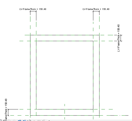
Then it is necessary to create the Mullions; to do it create a new family from template “Metric profile Mullion” (attention it is a bidimensional object and the principals commands are in menù "create")


Then load into the project and select menù "Architectural" – "Mullion" and click on Edit Type

Duplicate the type and and change the name in LV-MullionRectangularA and select the Mullion that you have just created.

Then click on "All Grid Line" as shown below and select the grid


Now load the door, that you created before: LV-Door-cw.
Select the Curtain Wall and select a panel and remove the thumbtack and go to Edit Type: in family select the door, if it is not present in the list do click on Load button and load it.

Now in the Curtain Wall there is a door.

You can aslo delete the mullion below
Now modify the door and draw the lines that indicate the aperture. Select the lines and click on Convert Lines Button and select Opening (projection) in Subcategory (in this way the lines are visible only in plans view) as shown below:

Then reload into project
Sab, 27/12/2014 - 19:39
 Daniele.tricarico
Sab, 27/12/2014 - 14:17
Daniele.tricarico
Sab, 27/12/2014 - 14:17
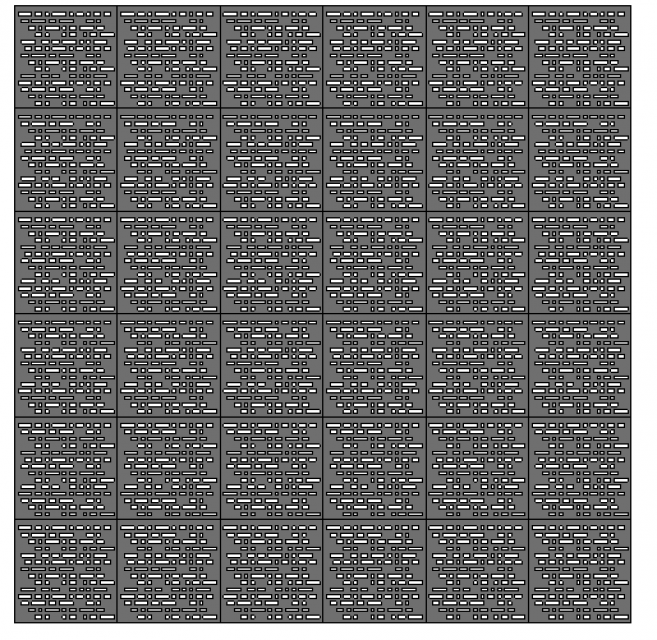
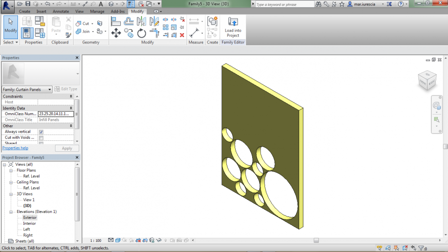
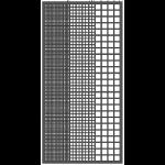
Per questa consegna ho deciso di progettare un pannello di acciaio anotizzato forato. Ho studiato i fori, realizzati sul modulo del quadrato, in modo tale da poter consentire una diversa permeabilità alla luce giocando sulla distanza tra questi e la loro grandezza. (4.1)
4.1
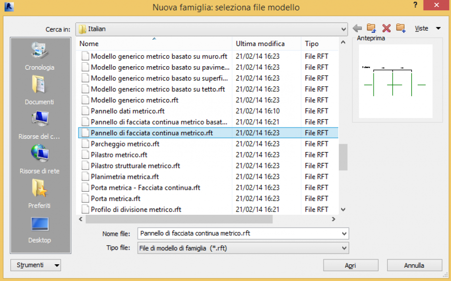
Per poterlo realizzare in Revit ho aperto una nuova famiglia e considerando che avrei dovuto realizzare un pannello per realizzare facciate continue ho aperto la famiglia “pannello di facciata continua metrico”. (4.2)

4.2
Servendomi di piani dei piani di riferimento ho realizzato il mio pannello parametrizzandolo in tutte le sue dimensioni e quindi l’ho estruso.(4.3)

4.3
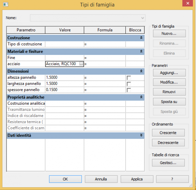
Per finire la famiglia del mio pannello ho deciso di assegnarle il materiale, ovvero acciaio anotizzato, e quindi ho parametrizzato anche questo. (4.4)

4.4
Per creare una parete costruita con i pannelli, da me realizzati, ho aperto in Revit un nuovo progetto metrico. Per realizzare la parete ho cliccato su architettura e quindi su muro.(4.5)

4.5
Cliccando su proprietà del muro ho potuto selezionare i parametri della parete.(4.6)

4.6
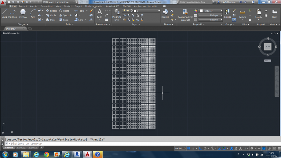
Per poter inserire la famiglia dei pannelli da me realizzato ho cliccato su griglia ed ho realizzato una reticolato all’interno della parete della dimensione adatta ad ospitate i singoli elementi. (4.7)

4.7
Cliccando sui parametri della parete ho potuto inserire all’interno della griglia i pannelli da realizzati inserendoli all’interno della voce “pannello di facciata continua.(4.8)

4.8
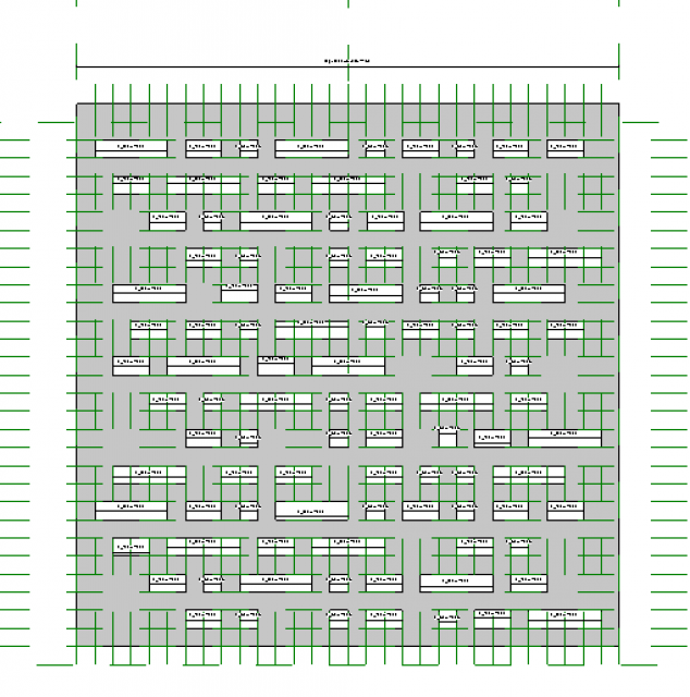
A questo punto ho ottenuto la mia parete realizzata con dei pannelli prefabbricati in grado di filtrare la luce in modo diverso asseconda le esigenze richieste dagli ambienti retrostanti. Per enfatizzare questa caratteristica della parete da me realizzata ho inserito la luce le ombre proiettate che sono più rade dove i fori sono più grandi, e quindi penetra più luce, e più densa dove i fori sono più fitti e quindi filtrano in modo più efficace i raggi solari(4.9)

4.9
Tale effetto è stato ottenuto semplicemente giocando parametricamente con le distanze tra i fori e lo loro grandezze. (4.10)

4.10
Sab, 27/12/2014 - 14:29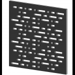 ANTONIO SCIROCCHI
Ven, 26/12/2014 - 09:23
ANTONIO SCIROCCHI
Ven, 26/12/2014 - 09:23
For this delivery we had to create a facade composed of various panels.
I had decided to think a new panel.
Step 1 I open a new file family -> Metric curtain wall panel (i create the single panel)
Step 2 I use the reference planes to create the shape of panel.
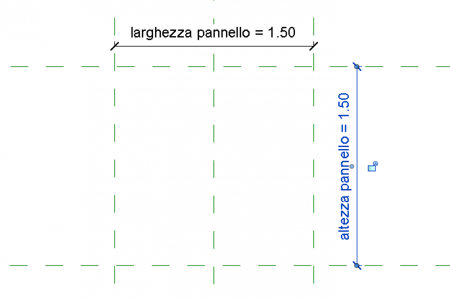
Step 3 i select the reference planes and i give it a parameter (add parameter).
larghezza pannello
- lunghezza pannello
- spessore pannello
Step 4 Now i can create an extrusion create -> Extrusion -> draw -> rectangle.
then i aligned the rectangle with the reference planes.
Step 5 i create a set of reference planes to realize the openings. With the command “void extrusion” i create the openings.
Step 6 there are three type of openings ( 0.05 cm, 0.1 cm, 0.2 cm). I assigned at each opening a new parameter.
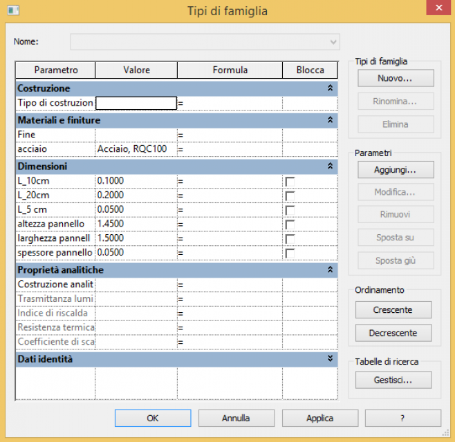
Step 7 Now i can compose my facade system with the panels.
Step 8 i open a new project file -> Project ->template file ->none -> metric. With the command “Architectural wall” i create a facade.
Step 9 i create a new view view -> elevation
Step 10 from the folder properties, I click edit type and rename the facade
Step 11 Check to the facade a grid that allows me to apply the panel.
Architecture -> Curtain grid.
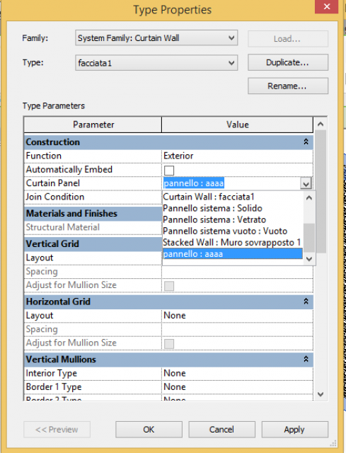
Step 12 Now i load into the project the panel. In the Curtain Wall Type Properties i set my panel as the panel for the curtain wall.