 Matteo Molinari
Lun, 15/12/2014 - 15:20
Matteo Molinari
Lun, 15/12/2014 - 15:20
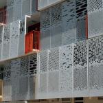
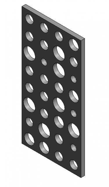
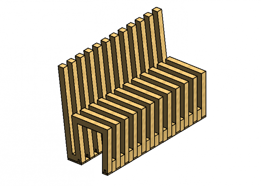
In this delivery we were asked to design a curtain wall. I decided to design a faced similar to the one in the headline picture. Since I'm designing a facade is important to understand the solar radiation that the facade recives; I tried to parametrize where possible so that the facade could variate according to which facade we are designing.
PART 1: The Family
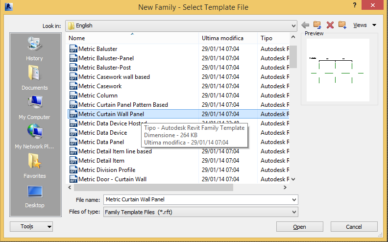
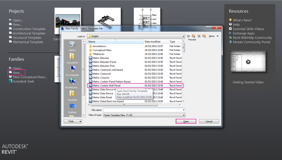
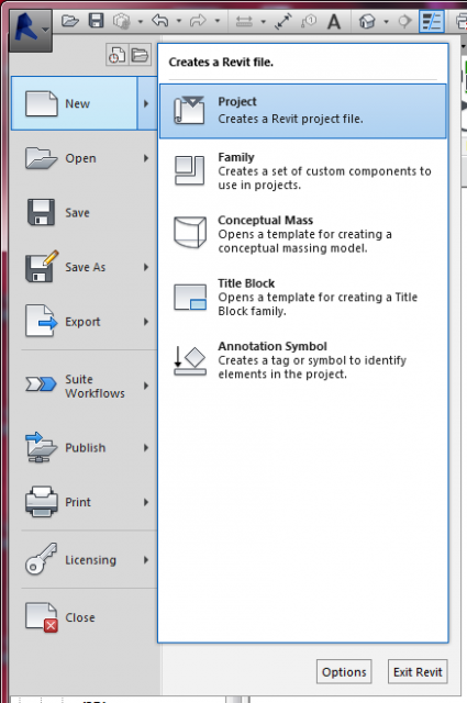
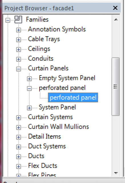
The first thing I did was to create a new family for my curtain panel. This time since we are drawing a curtain wall we don't have to use a metric generic model family but a METRIC CURTAIN WALL PANEL.(f.1)
 f.1
f.1
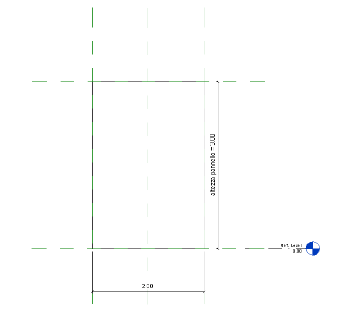
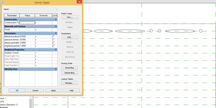
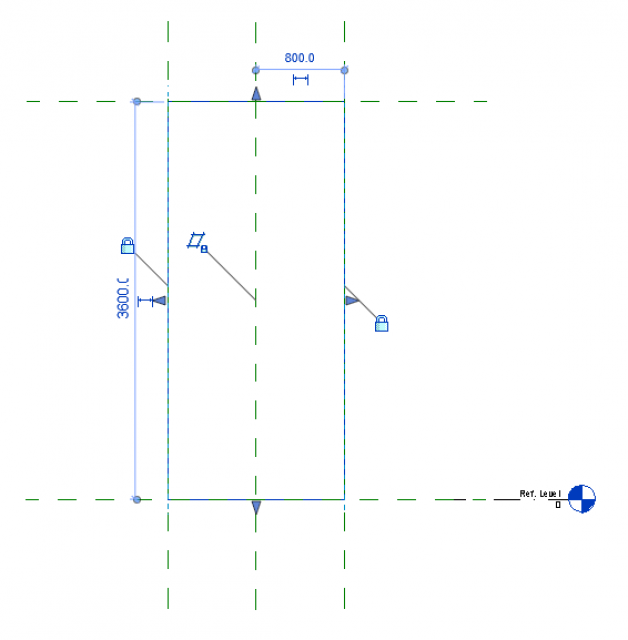
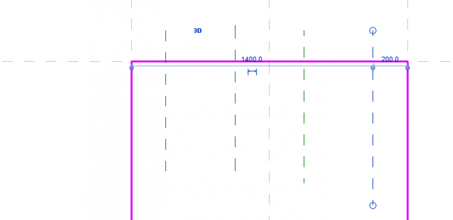
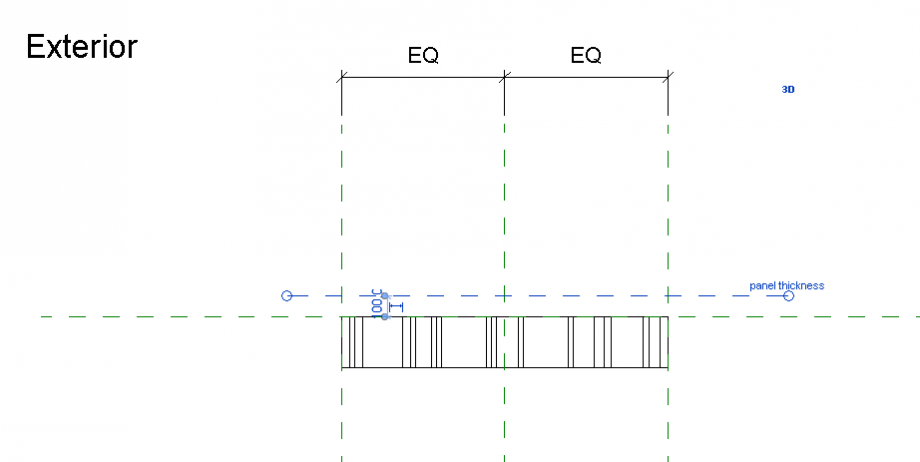
Then I had to decide the dimension of my panel. so I drew my REFERENCE PLANE, and then I EXTRUDED the panel. I blocked the dimension of my panel to the reference plane and the showed the quotes. The I set three parmeters to assign to the panel: altezza, larghezza e spessore. The base panel I design is 3x2x0,05m. (f.2)
 f.2
f.2
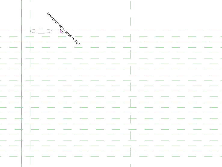
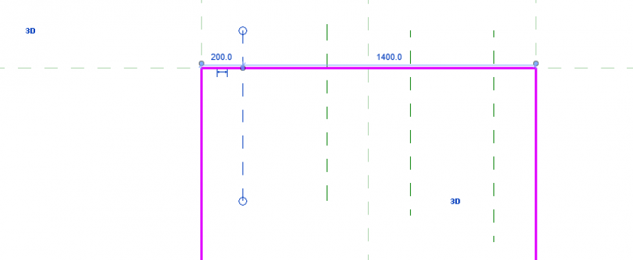
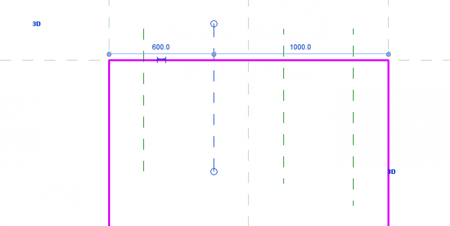
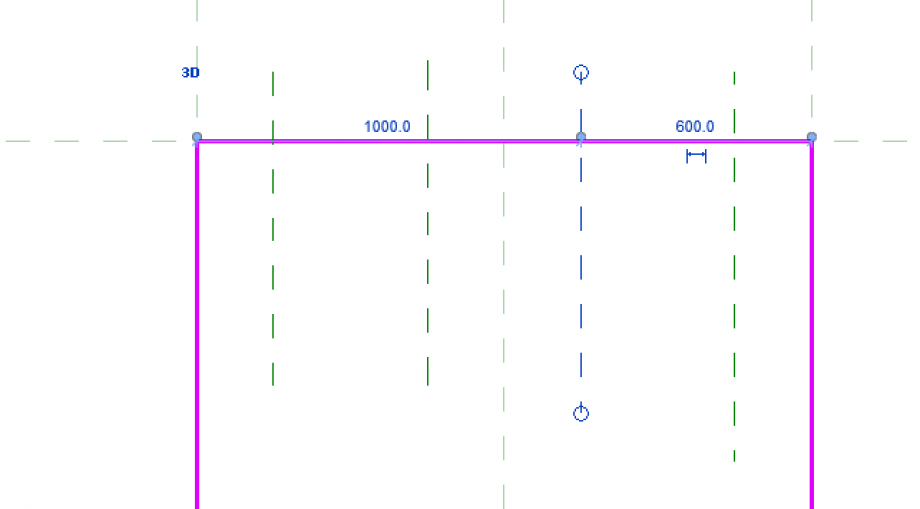
I drew my reference plane so that the holes will have a certain order. Each hole is orizzontaly distant from each other 0,04 m and each reference plane is vertically distant 0,10m. (f.3) Then I did a VOID EXTRUSION and drew three types of holes. I parametrized this holes so that I can change the height if needed. (f.4-f.5)
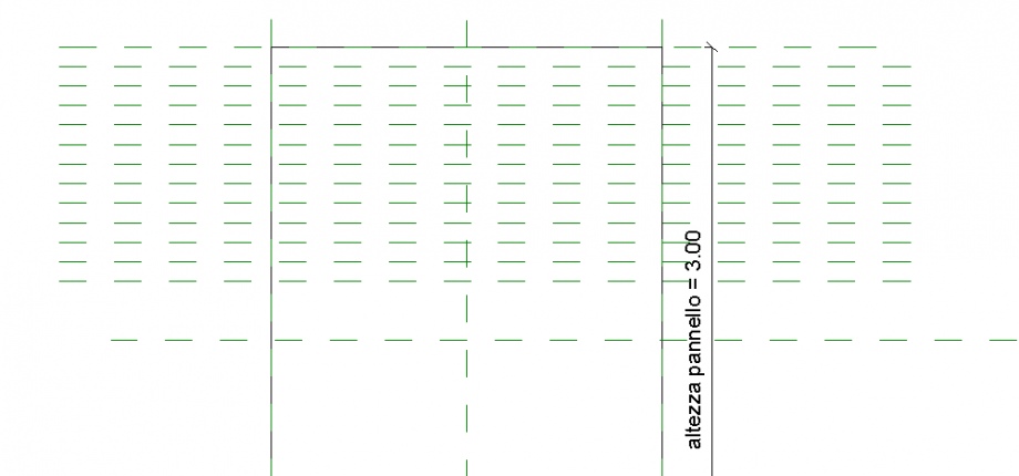 f.3
f.3
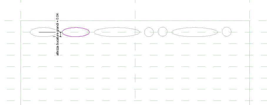 f.4
f.4
 f.5 (an example of changing the parameter of the voids)
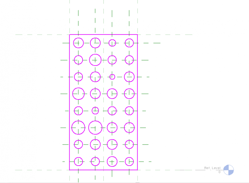
Then I went on designing the bigger holes for half of the panel. (f.6)
 f.6
f.6
Then I started designing the smaller holes, in the inferior part of the panel. The same way I did with the bigger ones. (f.7)
 f.7
f.7
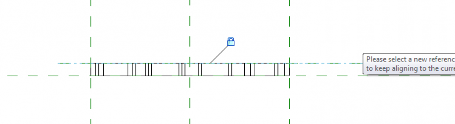
The important part now, is to parametrize the vertical distance between the holes, so that if needed because of the exposition it can change. I quoted each refernce plan to which the void extrusion were blocked, activated EQ, gave a quote and parametrize it. (f.8) Then I assigned the parameter material, in this case alluminium.
 f.8
f.8
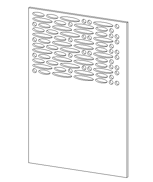
Now I have finisched my panel. (f.9)
 f.9
f.9
PART 2: The Project
It's time to create my project, so that I can create my Courtain Wall. I opened a new project, metric.
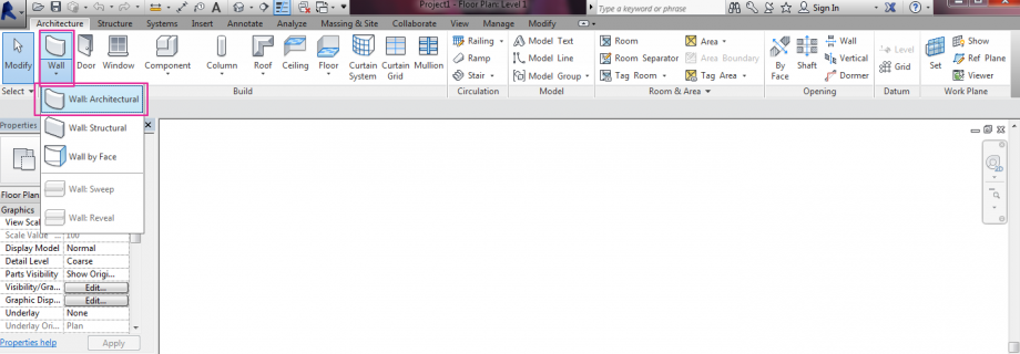
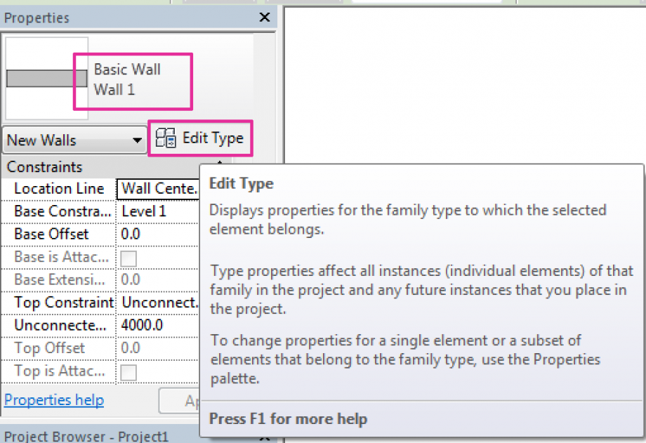
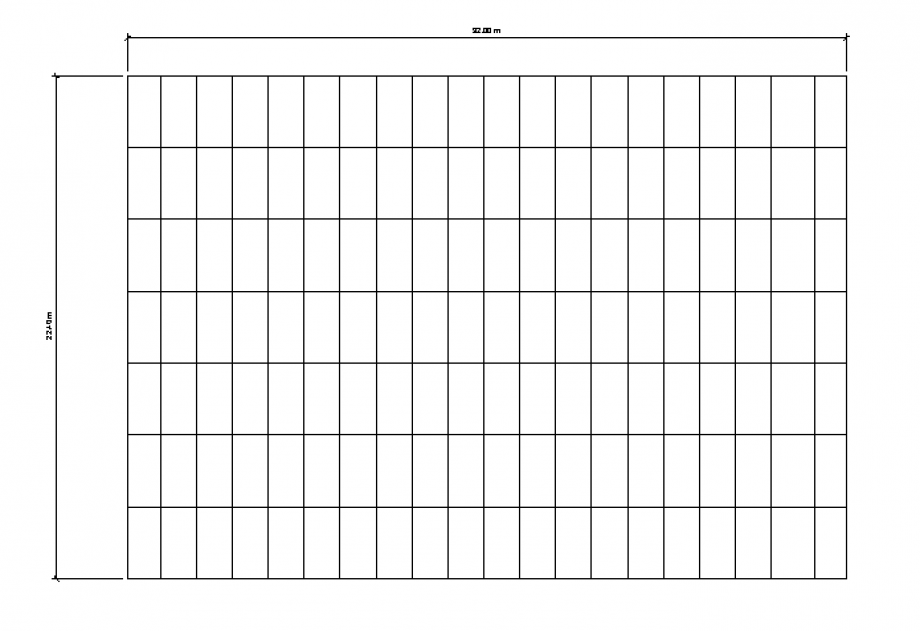
I used the comman ARCHITECTURAL WALL and drew it on my worksheet. Then I did EDIT TYPE and set the SISTEM FAMILY:CURTAIN WALL, gave a new name, in this case panel and duplicate it. (f.10) The wall is 12x12 meters, the depth will be given by the perforeted panel.
 f.10
f.10
I added a new poin of view with the command ELEVATION, so it's easier for me to model. (f.11)
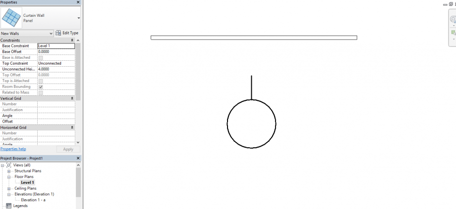 f.11
f.11
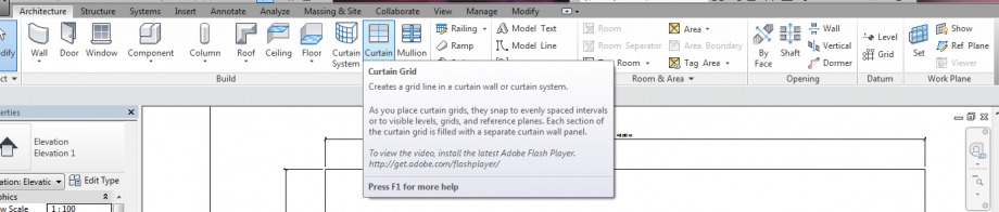
Then I used the command CURTAIN GRID so that I can divide my wall in areas as big as the panel I designed. (f.12)
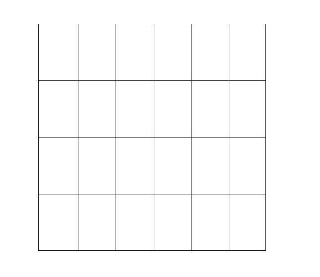 f.12
f.12
I loaded my family in to the project.
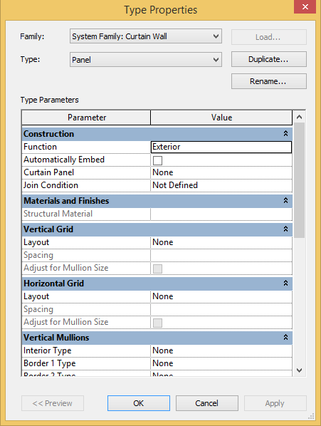
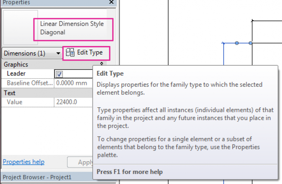
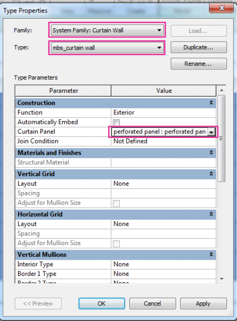
Then I selected my wall, and used the command EDIT TYPE, in the window where is written Curtain Panel I choose the panel I designed and load it. (f.13)
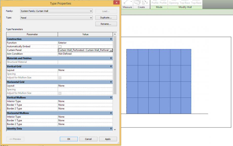 f.13
f.13
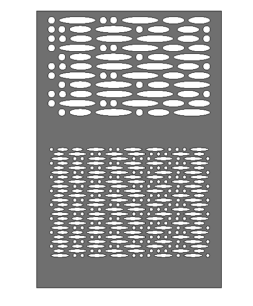
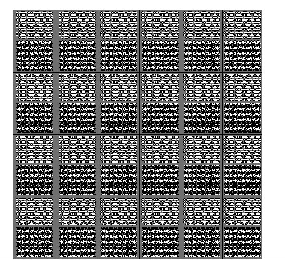
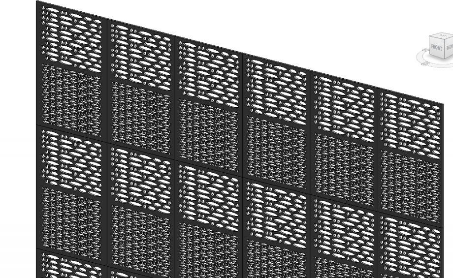
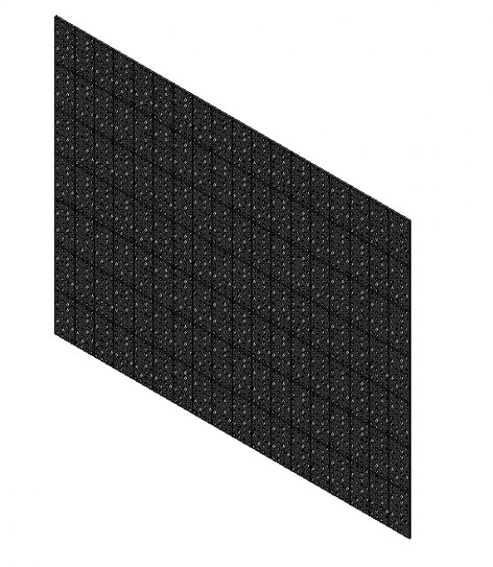
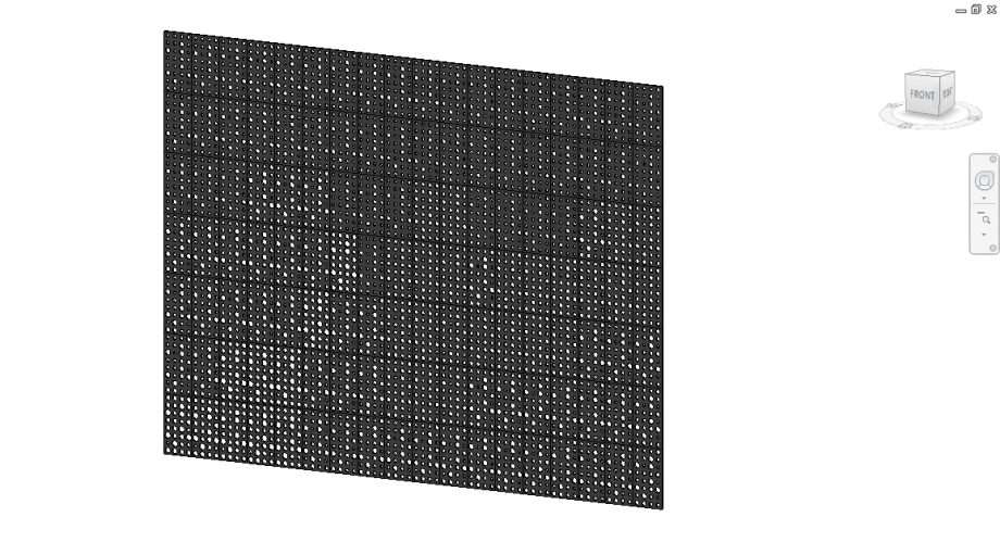
The Curtain Wall is finished. all the panels are loaded in the right place (f.14-f.15)
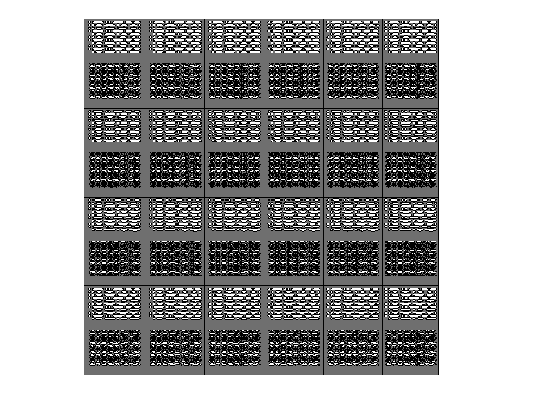 f.14
f.14
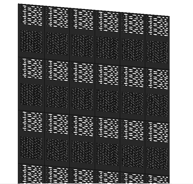 f.15
f.15
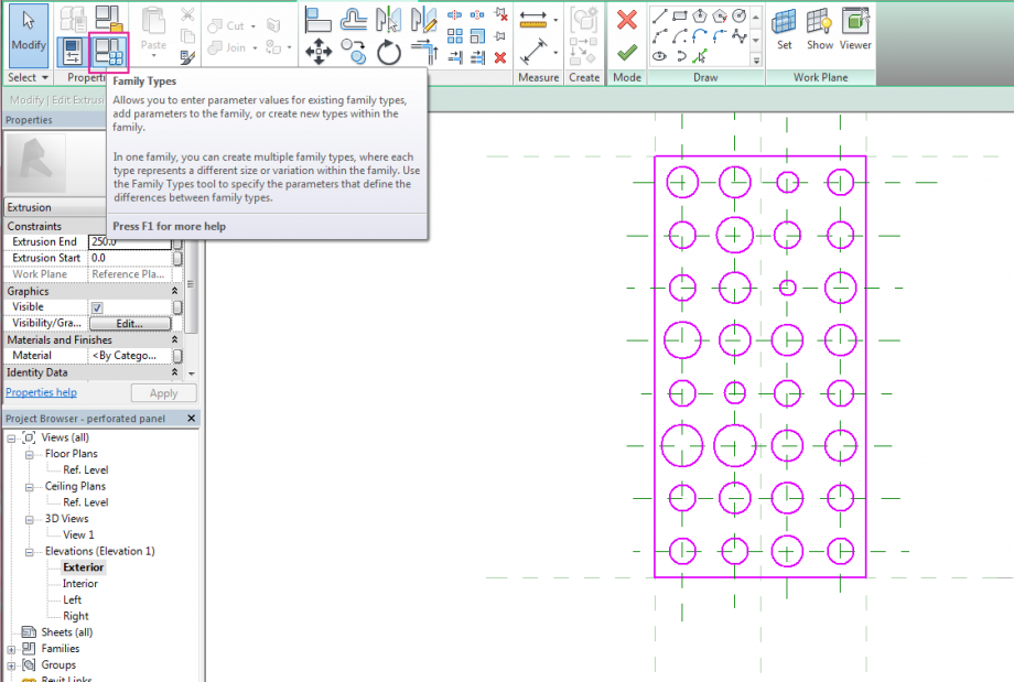
This is the panel with the base dimension I choose, but since every panel is parametrized I can just change the parameters and I'll have a panel with a different design. (f.16-f.17)
 f.16
f.16
 f.17
f.17
 Mabel Sorrentino
Sab, 13/12/2014 - 19:59
Mabel Sorrentino
Sab, 13/12/2014 - 19:59
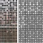
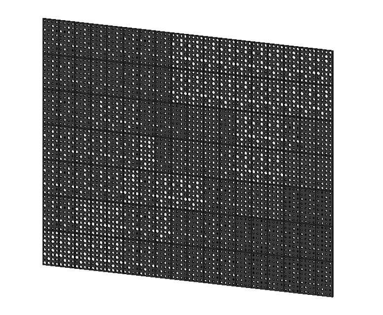
In this post I tried to reproduce a curtain wall facade inspired by the one realised by Herzog and De Meuron in their M. H. de Young Memorial Museum in San Francisco.
As I know, the workflow they used to get this amazing result was longer and more refined than mine. The reason why I let myself be inspired by this project is because I found interesting the relationship between the diameter variation of the holes and the shade they provide inside.
So, I can start immediately to show my workflow.
PERFORATED PANEL
At first I shaped the panel.
I Created a new family> Metric Curtain Wall Panel (in this environment I shaped the component I wanted to be the basic module of the curtain wall facade)
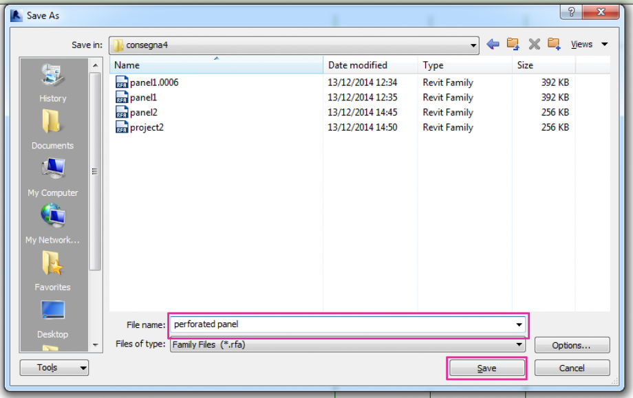
I Saved the file as a family
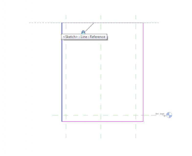
I Created an Extrusion. In the Exterior view I drew a rectangle> I aligned each side of it to the pre-formed reference planes.
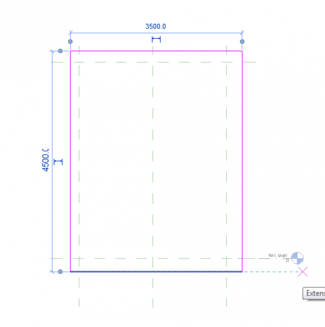
I gave the panel the dimension wanted.
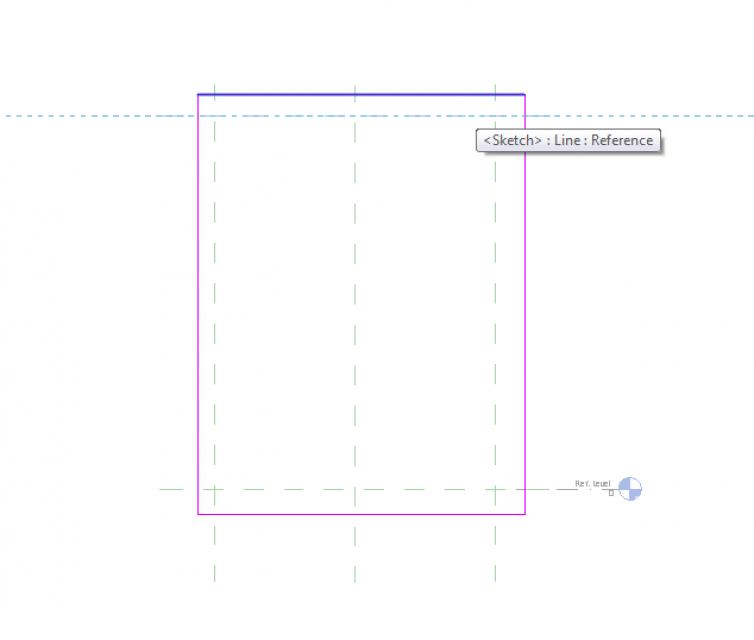
Then I started to draw reference planes in order to have guides when I needed to draw the holes after.
I kept in mind that in order to have a better result when I would have mounted all the panels together I needed to halve the space between the last column and the edge of the panel. So if I the space between two consecutive columns was 40 cm, the space between the last column and the end of the panel was 20 cm.
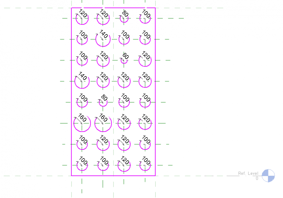
Then I drew the holes.
As my goal was to be able to control their diameter variation I assigned them a parameter.
 I assigned just instance parameters because I wanted to control each panel separately when I would came after in the project environment.
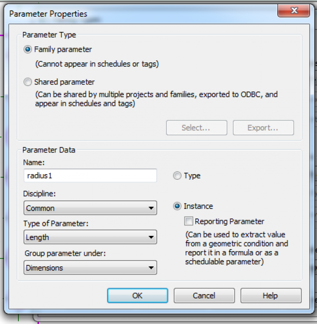
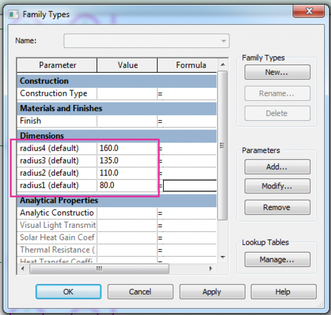
I assigned parameters to the holes’ diameter.
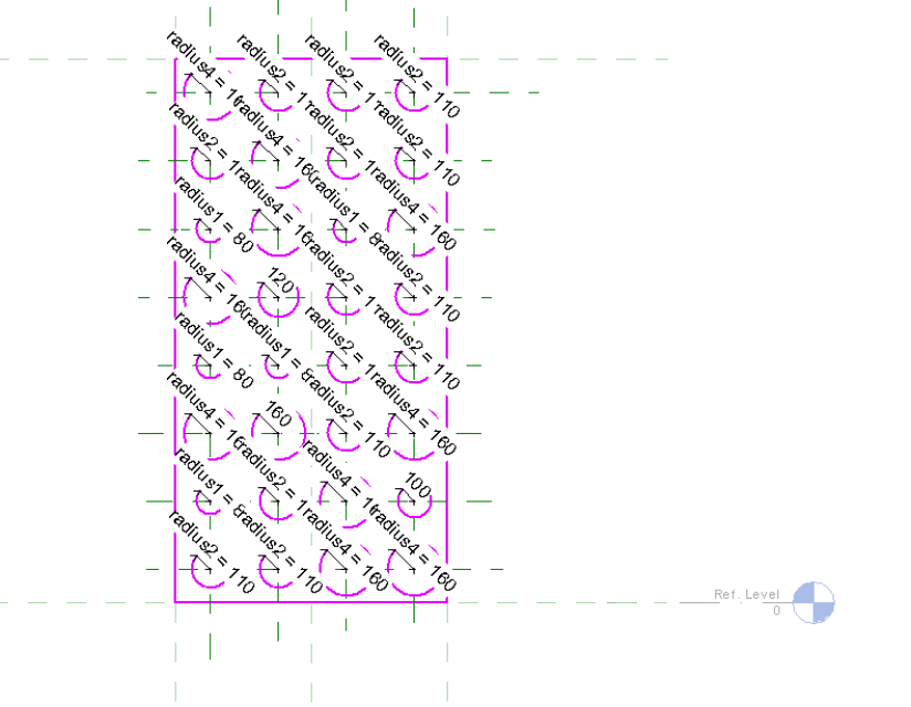
I made some corrections when I closed the extrusion just to adjust final result.
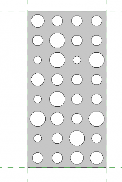
I created reference plane in the plan view to align my extrusion with. This was the final result.
CURTAIN WALL
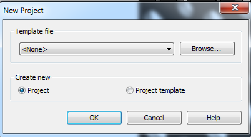
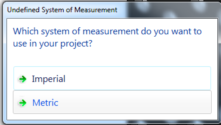
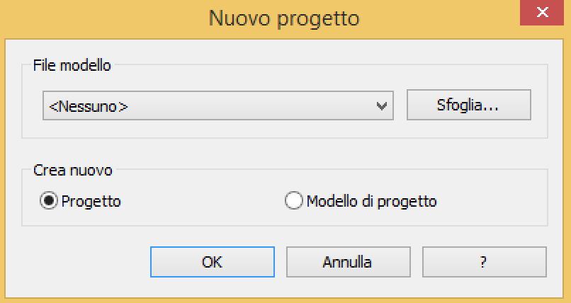
So, I created a new project file. New> Project> Template file> none> I chose metric as system of measurement.
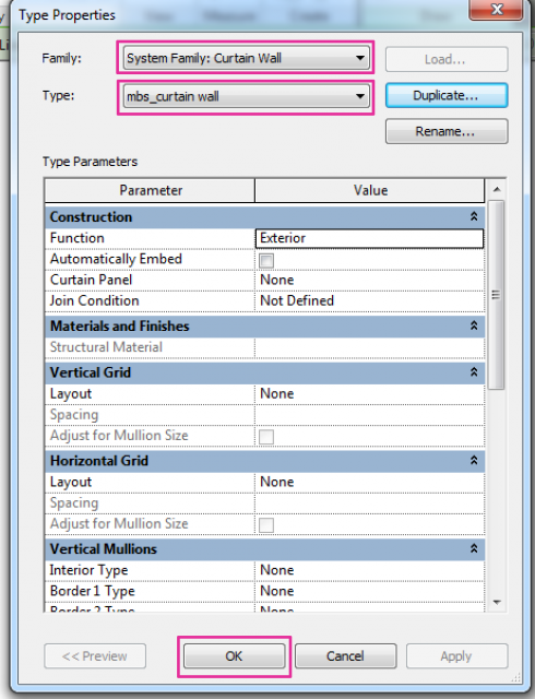
I created an architectural wall. Then I edited the curtain wall. Edit type (in properties tab)> System Family: curtain wall> I duplicated and renamed the type.
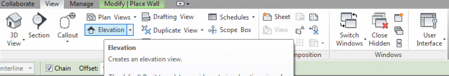
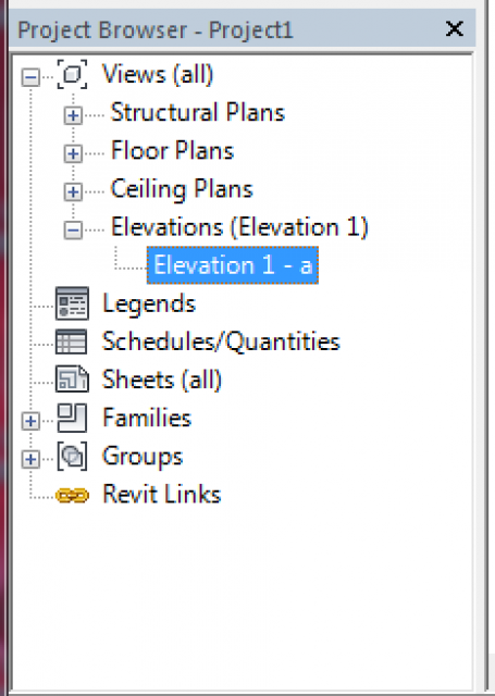
I added an elevation view. View> elevation> Project browser> elevation
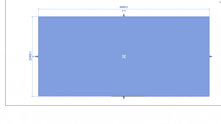
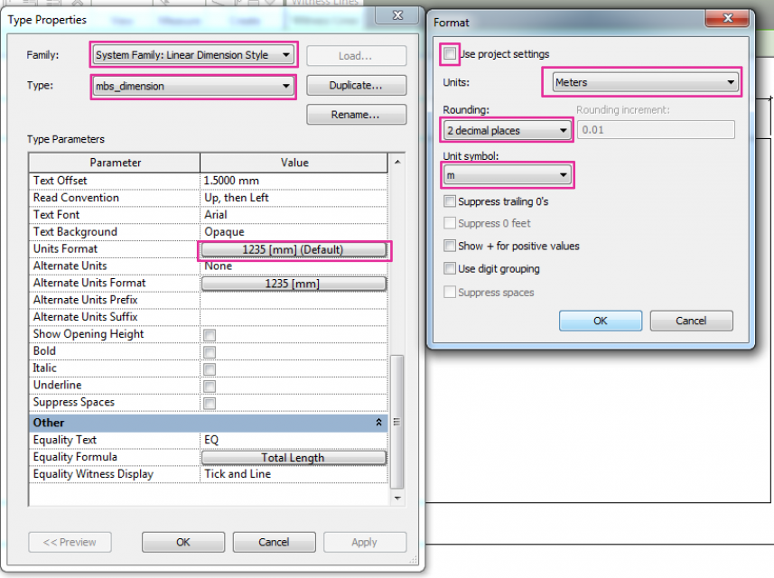
I gave the wall the dimensions needed and then I set as I want them to be.
I drew the grid. Architecture> Curtain Grid.
 I loaded into the project the panel previously shaped and it was immediately visible in the families, in the project browser tab.
In the Curtain Wall Type Properties tab I set my panel as the panel for the curtain wall.
At last I tried with some variation clicking on a single panel and varying the holes’ diameter values.
 Francesca Bottaro
Mar, 25/11/2014 - 15:44
Francesca Bottaro
Mar, 25/11/2014 - 15:44
Here you can find an article I wrote about the use of BIM within Italy and abroad, published on the architetto.info online magazine.
http://www.architetto.info/bim-i-vantaggi-mancati-per-un-italia-in-ritardo_news_x_25348.html?utm_source=home&utm_medium=home
 Francesca Bottaro
Ven, 12/12/2014 - 15:09
Francesca Bottaro
Ven, 12/12/2014 - 15:09

This year, just a week ago, I had the opportunity to present the RhOME for denCity project at the Autodesk Idol, an event within the Autodesk University in Las Vegas.
RhOME, by Roma Tre University, participated to the Solar Decathlon Europe 2014 in France, and actually won the international contest, for the happiness of all of us who worked several months, and several nights, at the project, and for the pride of the entire University, and Country.


What is Solar Decathlon. It’s an international competition about sustainable architecture that deeply analyses and evaluates a project as to ten different categories: Architecture, Engineering and Construction, Energy Efficiency, Communication and Social Awareness, Urban Design, Transportation and Affordability, Sustainability, Innovation plus Comfort Conditions, House Functioning, Electrical Energy Balance.
20 teams are selected all over the world to participate, and this year the organization asked all the teams to define a dwelling solution for their own Country or city of origin.

So we had to design a project for the city of Rome, a home for Rome, that means we had to face the complexity and the contradictions of the city and of Italy.

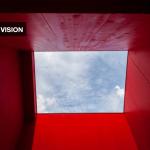
We decided to settle our project in the city slums, such as this one in the picture, where poverty and degradation meet history and beauty.


And we obviously had to design for the Mediterranean climate, which is complex, because we have to protect our buildings from cold as well as from hot weather, so that the sun is both friend and enemy.

Moreover, they asked us to design a complete, affordable, integrated urban solution, but also to extract a prototype, scale 1:1, of a single apartment, to be built in just 10 days.


So, for those who think that a sketch, an idea, an intuition, is almost where the architect’s work starts and ends, maybe it’s time to change the slant.

If we want to design the future, we have to design a process, open to innovation and able to face complexity.
That’s why we decided to move from a traditional linear model to a radial one, where the design is collaborative, and where the decathletes, the architects, are in-between figures, just between the project, obviously managed in a BIM shared platform, and the specialist point of view, that is often the greatest enemy of innovation.


That’s how we managed to define a complete model of the house, a constructive model, with all the real components of the project, that gave us the possibility to foresee and solve in advance the possible issues concerning production, and to detect on time the clashes between the systems to be installed


Managing the assembly phase on site and getting, at last, a totally functioning house in so short a time.


That’s how we also managed to research, design and prototype new, innovative and integrated solar production systems, such as the thermodynamic baluster and the photovoltaic shading screen.


That’s how we can define a sustainable solution, a solution that takes into consideration the complete lifecycle of every material within the process, creating virtuous cycles of regeneration, from waste into new resources.
That’s how we, as architects, can manage to ask our house to communicate the monitored data directly to the inhabitant, involving him in a process of ecological learning.

That’s how we can think of a smartcity within the city of Rome.

That’s how we reach beauty

and how we can try to offer our own Country the vision we have of the future.

 ANTONIO SCIROCCHI
Ven, 12/12/2014 - 15:08
ANTONIO SCIROCCHI
Ven, 12/12/2014 - 15:08
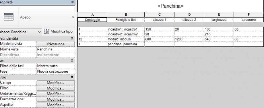
In this third delivery, we must create a schedule of the parametric object used for the second delivery.
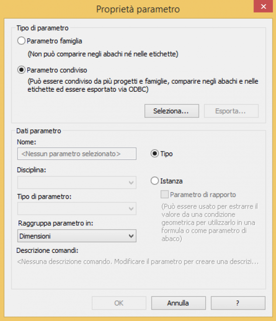
To make a schedule, i had to change the parameters of each component of family mother. This is because the old parameters weren’t shared parameters. Now the these new parameters aren’t only for a one object but they are for every component.
step 1 i open every family and i change the parameters.
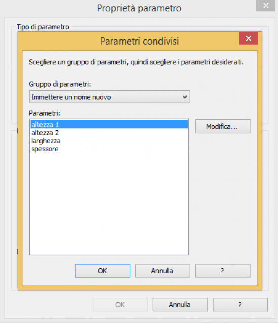
Parameter Proprieties -> Shared Parameters (before was Family parameter)
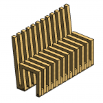
My bench is composed by three elements: Modulo, Incastro 1, Incastro 2. All the elements use the same parameters.
step 2 changed all the parameters, i can reload every component in the mother family (Panchina). But there isn’t need to shape a new bench, because i can replace and sostitute the old one with the new one. (Load family)
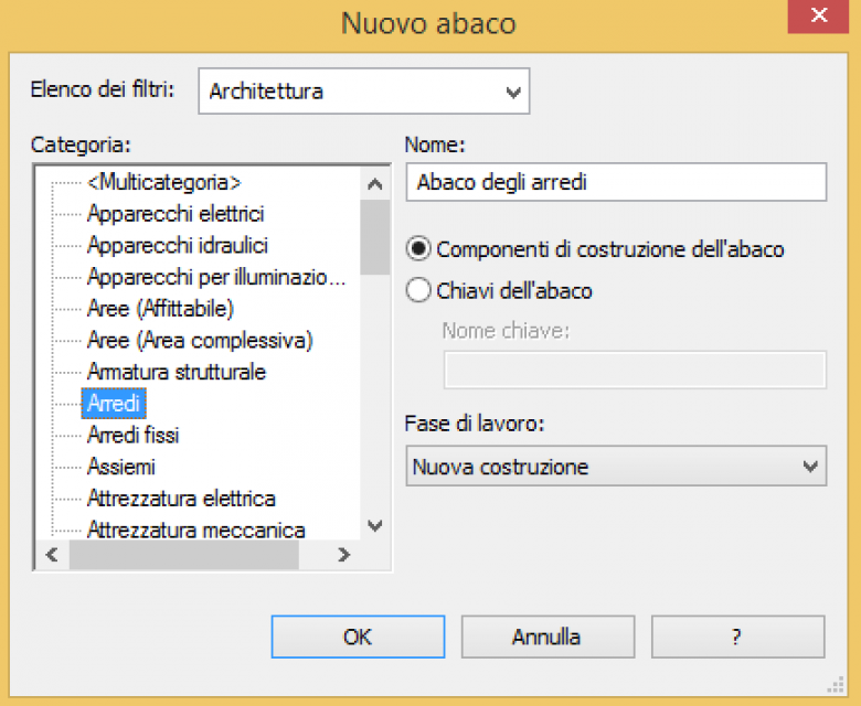
step 3 i decide that the bench must belong to a new categorie “Arredi”

step 4 Now i can load into a new project the mother family. (New project: metric)
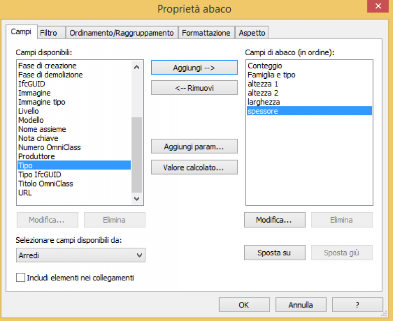
step 5 With the command Schedule, i can check all elements that compose the bench. So i choose “Arredi”, and than i can chose witch proprierties i want to show in my schedule. I chose: (conteggio, famiglia e tipo, altezza 1, altezza 2, larghezza e spessore).
Step 6 With the command Sorting grouping i can decide to change the order of elements.