


 Felipe Figueroa
Sab, 10/01/2015 - 12:05
Felipe Figueroa
Sab, 10/01/2015 - 12:05
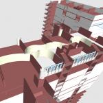
For this consegna i wanted to improve the fabrication process, for this i replaced the old system made of one element repetition, for a repetition of a group of elements.
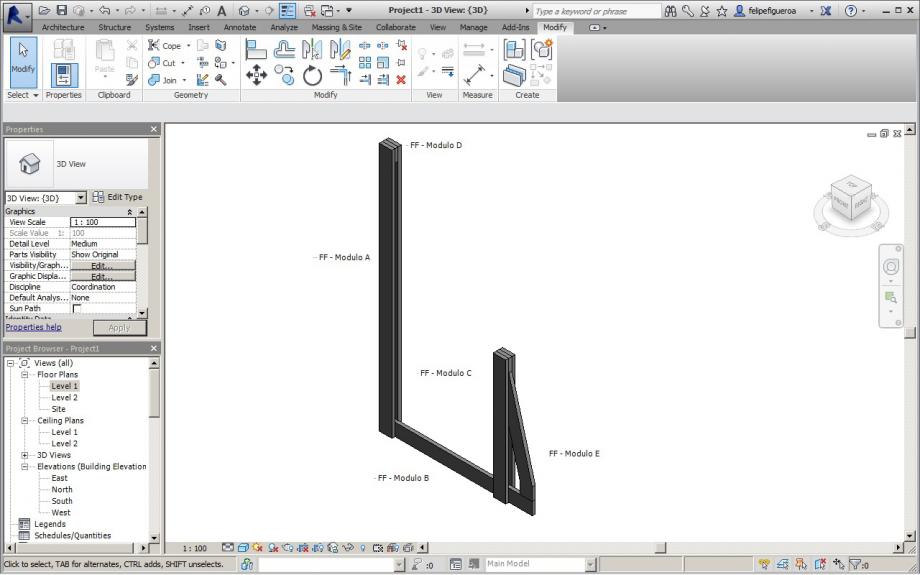
In this sense i dicided that i will work with 5 modules, that i called "Modulo A", "Modulo B", "Modulo C", "Modulo D" and "Modulo E".
The important one is the "Modulo B", this is the only module that changes and is the one that makes the floor of the station.
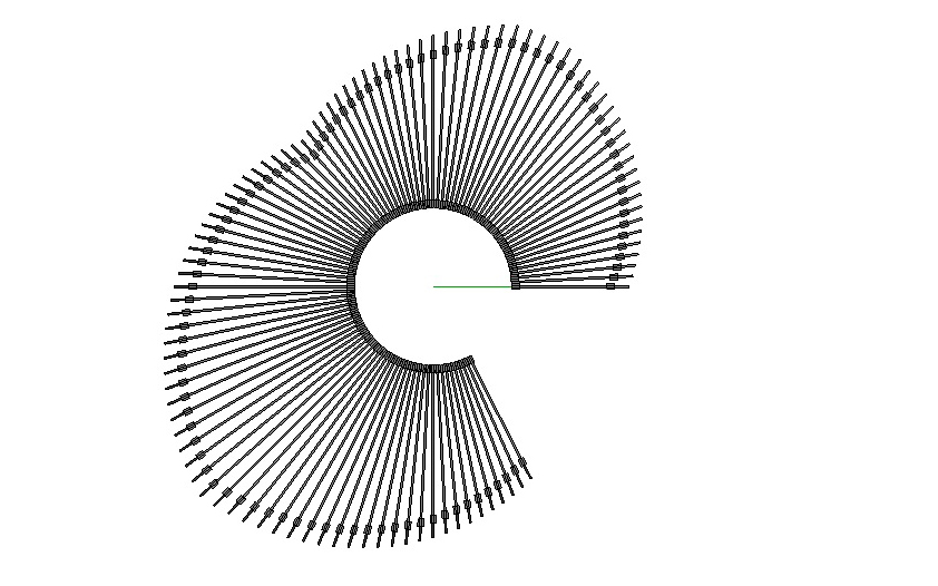
In this case there are 5 modules that create a group, this group is repeated with the command "array".
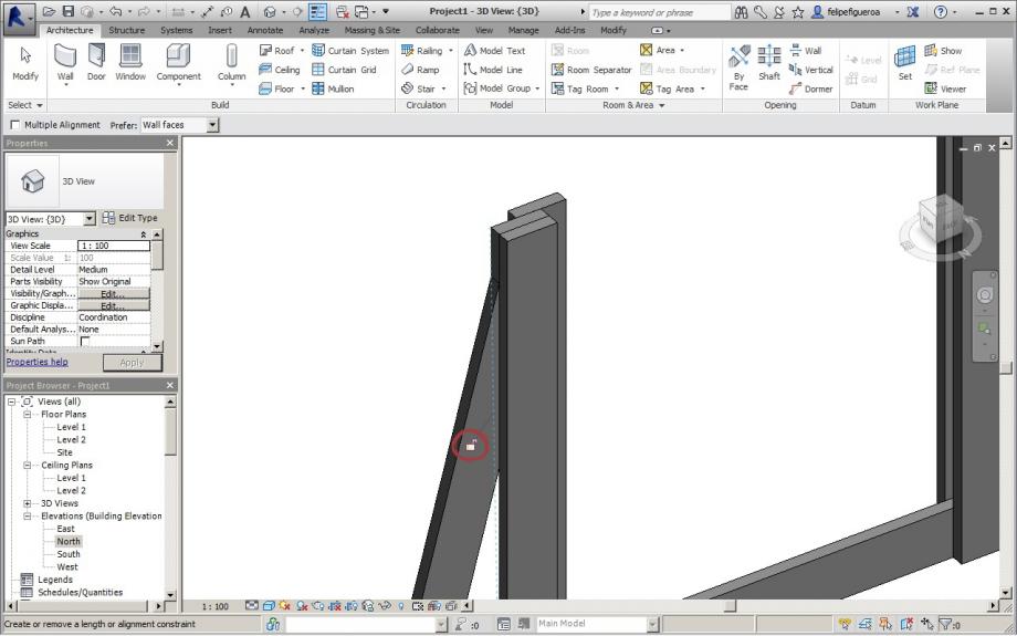
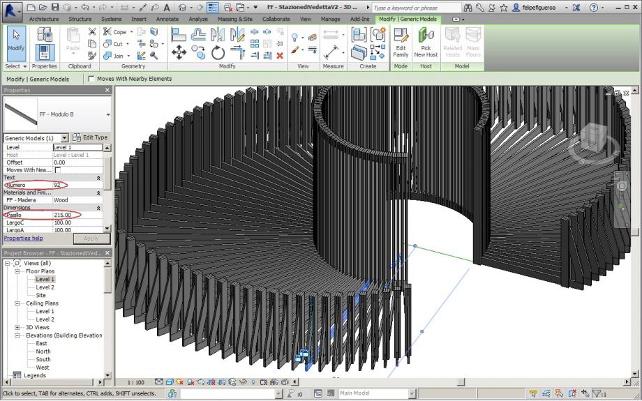
In this group the modules are aligned, the only parameter that is free to change is the lenght of the module "B", this way is more simply and easy to control the parametrization.
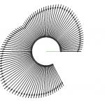
Like i said before, i used an radial array to copy the group of modules, 100 times and with 3º.
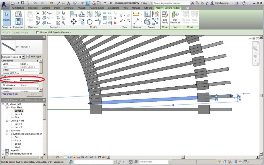
Also i created one parameter that is called "Numero", this is an text parameter that i will use in the schedule to know the number of the piece that i want to change.
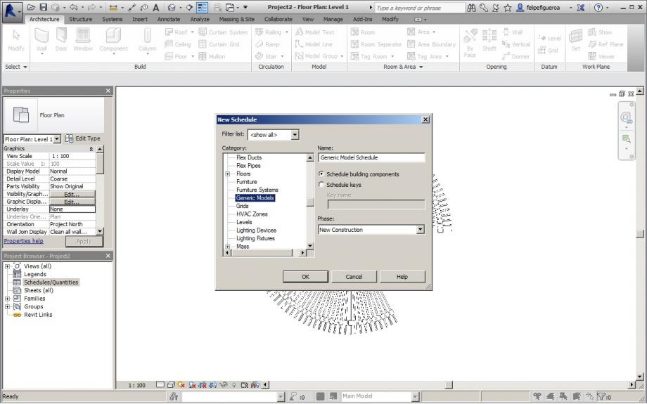
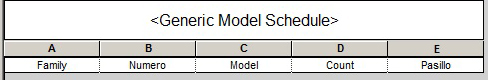
The Schedule is made by 5 types, the important ones are "Pasillo" that is the parameter used for the lenght of the "B" module and is the one that changes in the parametrization, and the "Numero" that is the number of the piece that changes.
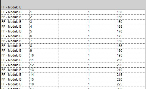
Here we can see that the Modules "B" have the number of the piece and on the "E" column we see the lenght in centimeters of the "B" module ("Pasillo").
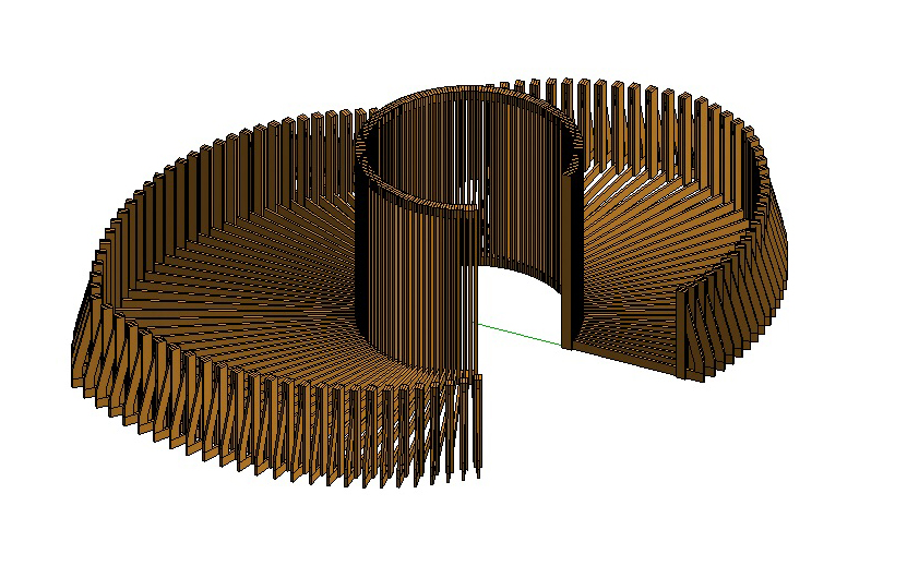
This Stazione di Vedetta can be made with standar pieces of wood (4"x1") and has a simplyfied parametrization, witch depends only of one paramter, but the result of the parametrization is very interesting, considering that is made with just one parameter.
The objetive is still to create 2 permanent spaces for seeing and one corridor to connect this 2 spaces, also in this design is the structural issue, and the assembly one.
Sab, 10/01/2015 - 12:41 Irem Bahcelioglu
Ven, 09/01/2015 - 18:31
Irem Bahcelioglu
Ven, 09/01/2015 - 18:31
Hi,
I uploaded the glue now but i don't have invitation. And my name isn't written in the list,so i cannot write my autodesk name. Could you please check the name list? If it is possible, I can add my name to the list.
Thank you
Irem Bahcelioglu
Ven, 09/01/2015 - 18:33 Manuel Andrè Bo...
Gio, 08/01/2015 - 14:49
Manuel Andrè Bo...
Gio, 08/01/2015 - 14:49
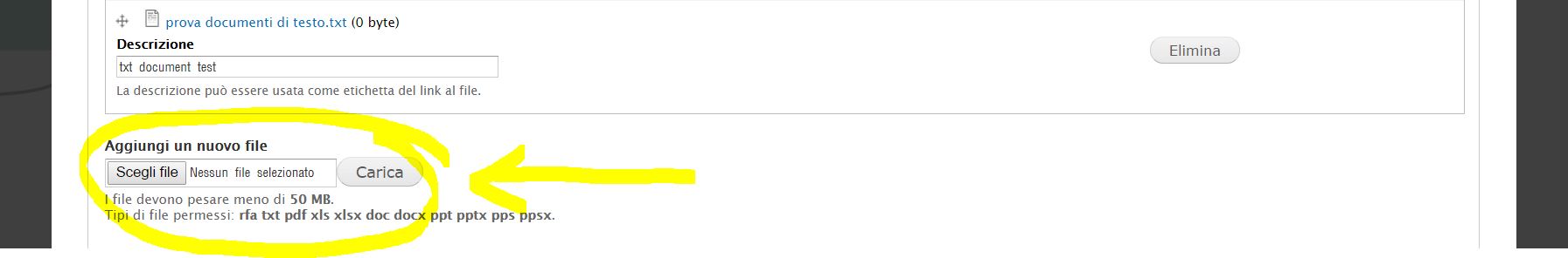
finally upgraded the possibility to attach files to our blog posts.
Now users, while compiling a new post, have a new field "Attachment" that gives them the possibility to upload an unlimited number of different file extensions (rfa, txt, pdf, xls, xlsx, doc, docx, ppt, pptx, pps, ppsx)
 StefanoConverso
Gio, 08/01/2015 - 16:00
StefanoConverso
Gio, 08/01/2015 - 16:00
Ecco il video della Lezione:

Gio, 08/01/2015 - 11:49
 StefanoConverso
Mer, 07/01/2015 - 14:52
StefanoConverso
Mer, 07/01/2015 - 14:52
Dear all,
Happy New year again, the 2015 starts great:
the first project is Glued and online!
It's by Laura Vellucci - great work Laura!


We look forward to more designs being uploaded soon!
In the next class you can ask us and try to solve all the problems
you might have at several levels.
We look forward to see your work and to meet soon!
The BIM_TPP team
p.s.
In order to have glue show materials, it seems that only Autodesk Library original materials are recognized,
please do your own try!
Mer, 07/01/2015 - 14:56