 Daniele.tricarico
Dom, 30/11/2014 - 21:09
Daniele.tricarico
Dom, 30/11/2014 - 21:09
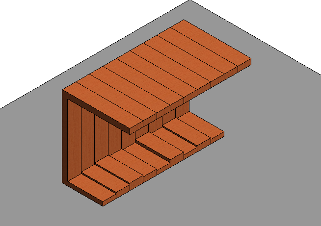
Per questa consegna ho cercato di realizzare un elemento d’arredo costituito da elementi realizzati seguendo precisi parametri in modo tale da poter assumere funzioni diverse al semplice variare di questi ultimi.
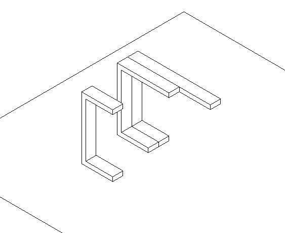
Per fare questo ho realizzato le varie componenti come singole famiglie basate su una superficie per poter facilmente assemblare l’elemento d’arredo, essendo le componenti vincolate su una faccia corrispondente a quella che sarà poi assemblata a contatto con quella di un altro elemento.(1.1)
1.1
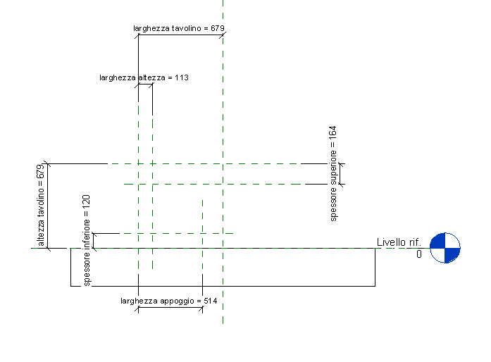
Ho iniziato a progettare uno dei listelli che avrebbero composto il mobile creando dei piani di riferimento su cui poi disegnare la sua sagoma (1.2).
1.2
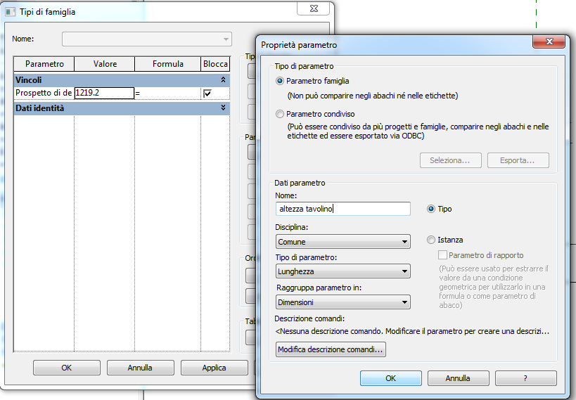
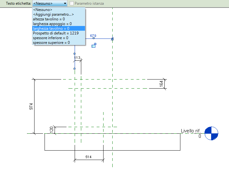
Dopo di che ho estruso l’elemento ed ho parametrizzato ogni sua dimensione e gli ho anche assegnato il materiale con il quale sarebbe dovuto essere stato realizzato. (1.3)
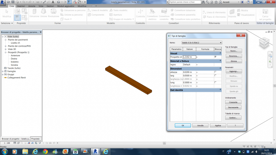
1.3
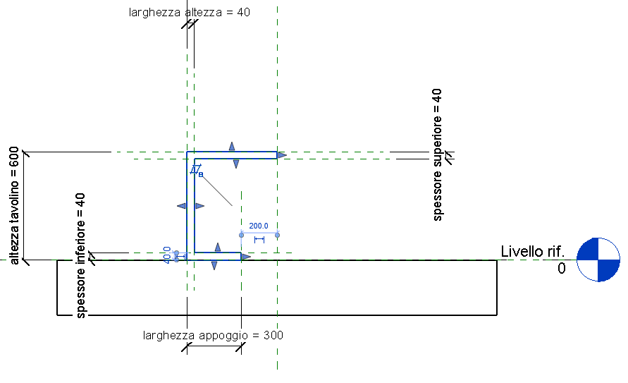
Allo stesso modo ho proceduto per realizzare la struttura portante dell’elemento d’arredo, realizzando una nuova famiglia basata su superficie e parametrizzandola in ogni suo aspetto per essere in seguito modificata facilmente asseconda delle esigente di assemblaggio. (1.4)
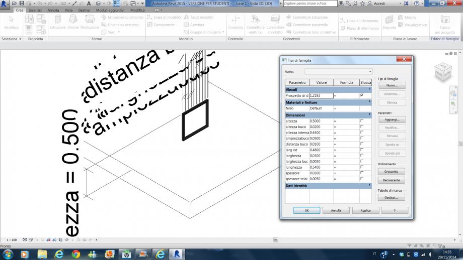
1.4
Allo stesso modo ho proceduto nel realizzare la famiglia madre che avrebbe costituito la base su cui creare il mio mobile, o meglio i miei mobili in quanto ho pensato di realizzare uno sgabello, una panca, un tavolinetto da soggiorno ed un tavolo utilizzando le stesse componenti variate solo nei parametri che le costituiscono. Alla fine ho ottenuto tre famiglia con le quali realizzare i miei oggetti, ovvero: la famiglia madre, la gamba e il listello. (1.5)
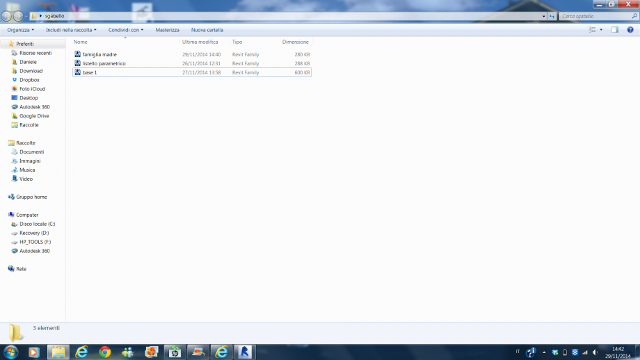
1.5
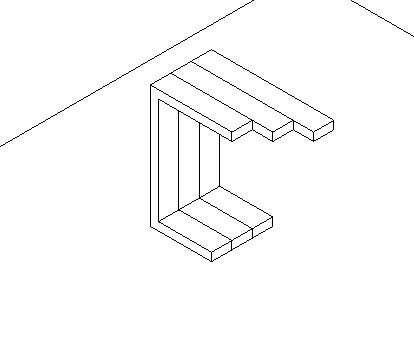
A questo punto ho aperto nella famiglia madre la famiglia gamba e quella listello ed ho iniziato ad assemblare uno sgabello utilizzando dei listelli governati da determinati parametri. Facilmente ho potuto “montare” i vari componenti essendo tutti vincolati ad una superficie corrispondente a quella di montaggio sull’altro oggetto.
Per realizzare la seduta ho posizionato il primo listello nell’apposito alloggio realizzato nella gamba e con il comando matrice, dopo aver selezionato il numero di listelli che mi servivano e il punto iniziale e quello finale in disporli, ho assemblato l’intera seduta ottenendo uno sgabello. (1.6)
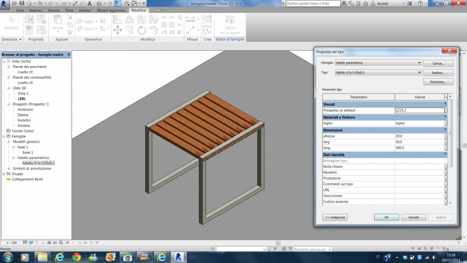
1.6
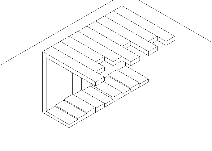
Semplicemente variando il parametro che governa la lunghezza dei listelli ho ottenuto un tavolinetto da soggiorno. (1.7)
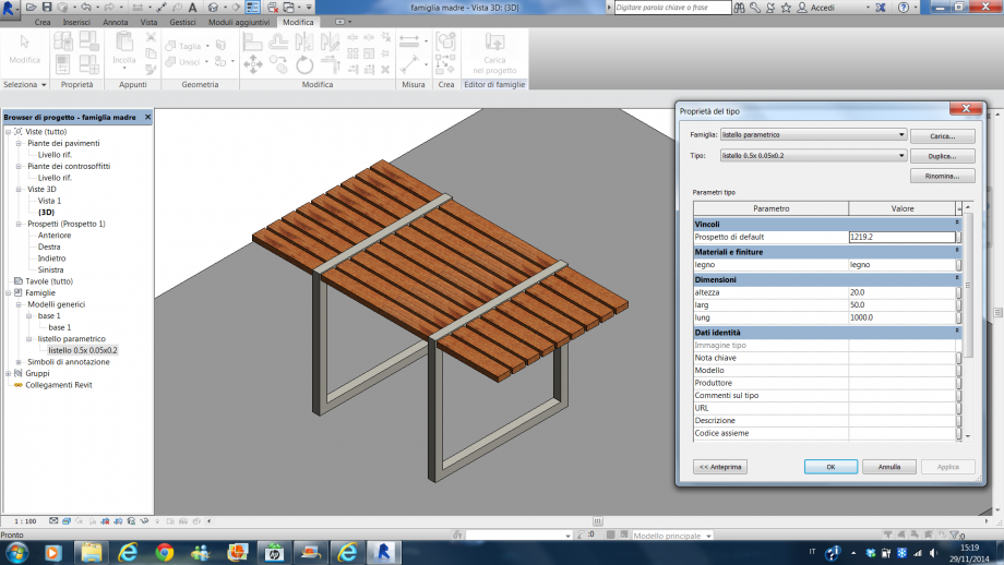
1.7
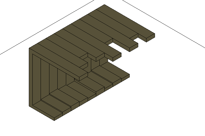
Invece modificando il parametro che gestisce la distanza tra gli appoggi e sempre quello della lunghezza dei listelli, ho ottenuto una panca da spogliatoio. (1.8)
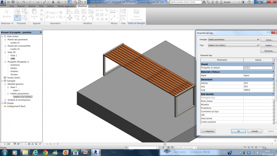
1.8
Ed infine, modificando l’altezza delle gambe, modificando la loro distanza e la lunghezza dei listelli ho ottenuto un tavolo da giardino. (1.9)
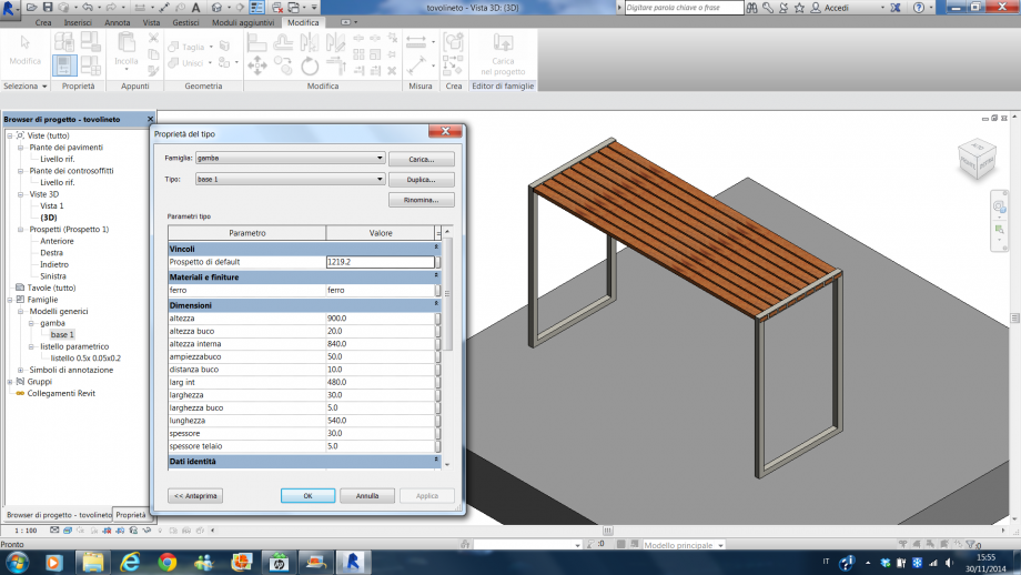
1.9
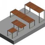
In quest’ultima immagine ho messo a confronto tutti gli elementi d’arredo ottenuti, per mostrare con quale semplicità un industria, partendo da un unico progetto di componenti, possa realizzare oggetti tanto diversi variando solo alcuni parametri di questi. (1.10)
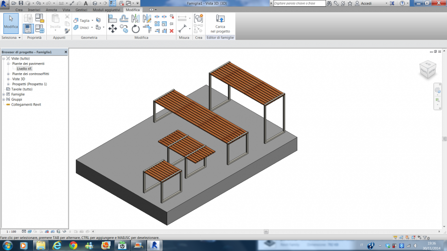
1.10
Dom, 30/11/2014 - 21:18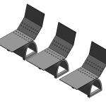 Natalie Ruggiero
Dom, 30/11/2014 - 20:43
Natalie Ruggiero
Dom, 30/11/2014 - 20:43
Hello,
after my second delivery I tried now to create a schedule for the produciton
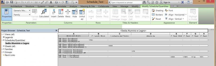
so I added the shared parameters and then tried to create the schedule.. but I cannot read it because I can not change the size of the row.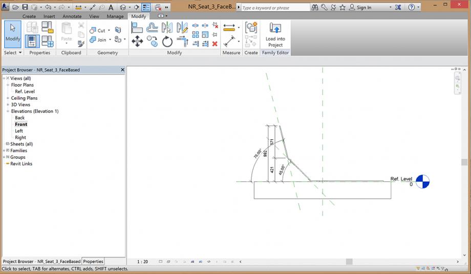
Till yet I didn't added the second version of the chair (the variable part) because I want to be sure first how to get a readable scedule.. I know in the top taskline there is a field where I usually should be able to change the size of the rows but its grey, I cannot select it. I tried many different ways..
 Nicola Moscheni
Sab, 29/11/2014 - 22:44
Nicola Moscheni
Sab, 29/11/2014 - 22:44

In my first approach on the parametric design I decided to reproduce an existing architecture.
Recently I see the intervention of energetic renovation for the building of the Ex Post Office in Bolzano, made by Michael Tribus Architecture in 2006. It has been the first project in Italy that achieved the “Passivhaus” protocol. It represents the leading project in sustainable architecture in our country.


One the of the most important elements is in the facade.The position of the original windows (1954) is maintened, but the external wall surface is designed so that the intrados of the windows change their dimensions in order to control the solar gains inside the building. More the external outline of the intrados is bigger, more the sunbeams can enter inside. Viceversa, for example. if I want less direct illumination inside the intrados is designed smaller.
Note: I think this considerations are essential to concieve my project. More I understand the principles of the facade easier I can design my model.
I want to model “my” facade as a modular system. Each window is linked to a basic module where the position and the dimension of the glazing is always the same. The variation element is the intrados outline. The parameters inside the module are the distances between the sides of the external outline and the edges of the module
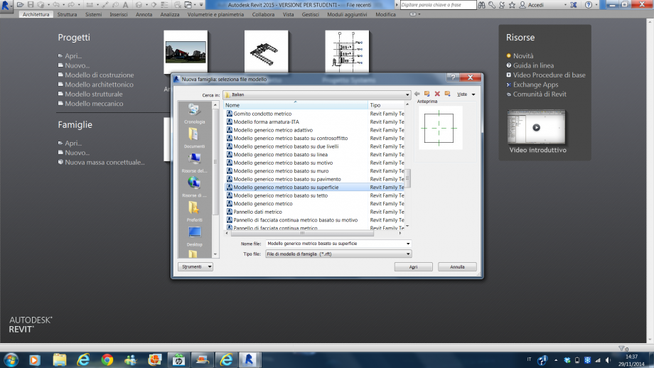
Let’s start! Open Revit and ereate a New Family with Generic Metric Model template.
First step: the order most of all! SAVE immediately the family. Assign initials and an appropriate name to your project to make your work recognisable. It’s very important when you do teamworking. People using your files need to ask about details, to congrats with you about your good job or to argue with you in case of disasters (this last case belongs to me more than the others).

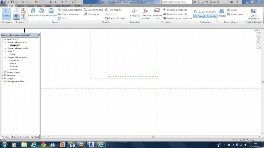
From Create panel select <Reference plane> (shortcut <RP> ). This leads you to have guides to follow in the definition of the shape. Draw four planes.

To place the object in the center of the space you have to center the planes to the default references of the model. To do that use <Alligned Dimension> that measures the two placed reference planes with the middle default plane. It appears “EQ”. Clicking on it, the two dimensions will be always identical one to the other, equal. [I discover it thanks to a comment of Manuel in an old post of Erica].


With a second dimension between the two RP you can set up the length of the module selecting one plane and typing the measure or dragging the plane. Do the same for the orthogonal planes. I create a perfect square 4x4m for my module.

For my module I create a simple rectangular extrusion. <Create> | <Extrusion> and select the rectangular profile for the <Draw> panel to draw the base of the extrusion. It’s important not to draw the base coinciding with the RP to have more control of the model.

Indeed, with <Align> (shortcut <AL>) you can adjust the side with the reference. So, AL, click the ref. plane and click the side of the base. Then click the lock to fix the between this two elements.


Repeat for the other sides and click the green tick to end the extrusion.
Go to the Front view (you can find it in the Navigator of the file). To fix the height of the extrusion draw a RP and aling the top side with it. (h=0,40m)

Now the flared intrados. It has the peculiarity of the two different outline. I tried a lot of solutions, ineffective, till at the end...I saw the post of Lais. Use <Void Forms> | <Void Blend>. The Void Forms remove part of a solid 3D shape and help to obtain a hole inside the module. The blend extrusion is shaped drawing the bottom and the top base separately: the bottom is the hole for the window, the bottom is the external outline of the intrados.
Draw the bottom base as a rectangle with dimensions 1,80x0,80 m, centered in the module width and 1,2 m from the bottom. Always use the reference plane and the align function.

Click <Edit Top>. The top base has different references. To draw it use dimensions between new reference planes and the planes of the main module. These dimensions are the parametric elements of the model. Once drawn the reference plane, use dimensions and go the <Label> menu and <Add Parameter>. Create the parameters (Instance) top, bottom, left, right. These are each variable side distance of the external outline of the intrados. (Remember to align the side of the top base with the reference planes).


Green tick to close the extrusion and remember to adjust the height of the blend void, the same of the module one.
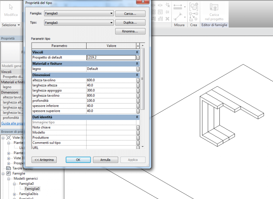
Go to the 3D View and the Shaded Mode. You can open the <Family Types> window to see the parameters of the model. ![]() Try to change them to see the modifications of the shape.
Try to change them to see the modifications of the shape.


Now it’s time to go into the project space. Create a new project and name it properly. In the family click . In the project space the family maintain the parameters. If you select the module you can find them in the Properties panel.

Now I can copy the module to design the whole facade and then change the parameters in every single module.


But we can do more. Return in the family and add the window. You can lift up the bottom base of the Void Blend, insert a new Void extrusion to obtain the space for the window and the insert a new extrusion for the glass.

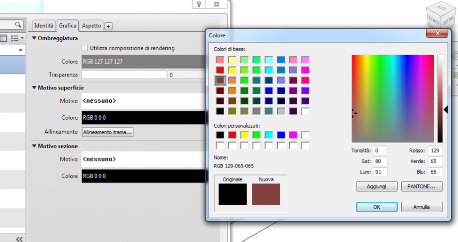
And materials? Go to Family Type window, clic <Add Parameter> and select a Material Parameter (Instance). Under the Value column you can click the little grey square to enter in the material library and choice what you want for the external finishing and the glass. After that you can assign this parameters to the material properties in the main panel. (For more deails about materials wait for the next posts where I will explain better this aspects).
Now You can load again the family in the project. The most important thing is that you can overwrite the "new" properties maintaining the structure of the project.

My personal error. I try to rotate tha facade, because I designed it in the Floor Plan, starting from the family. Revit doesn't allow me to rotate the elements. It's obvious...if I designed the family horizontally, in the space project it's the same. so remember, modelling in Revit is modelling the reality.
This was my first attempt. I'm sure that there is an easier, faster and more correct way to do this. But with my proficiencies at the time, this is the best for me.

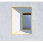
My first render in Revit, with a fast post-production. Ok, I can do more and better but I'm going through a new tool. Step by step
Dom, 30/11/2014 - 00:21
 julia medrado
Sab, 29/11/2014 - 22:22
julia medrado
Sab, 29/11/2014 - 22:22
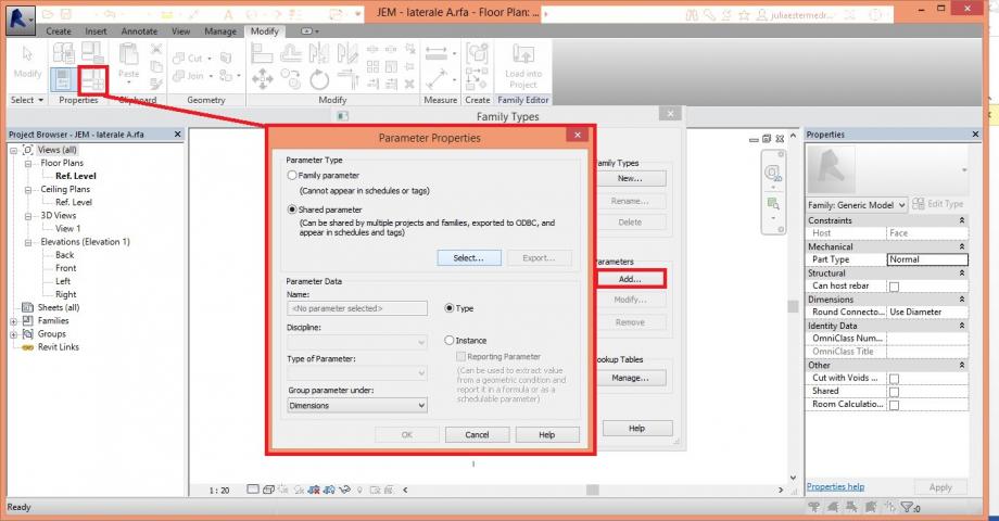
1.Ho cambiato i tipi di parametri associato direttamente alla misura per i parametri condivisi. Parameter type>>shared parameter>>add>>edit>>create...
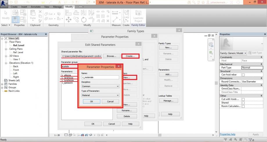
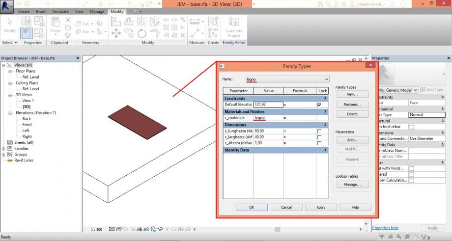
2...ho salvato il archivio di parametro , dopo ho creato un nuovo grupo di parametro chiamato "scatola" e dentro di questo grupo ho aggiunto tutti i parametri bisognava (c_altezza, c_larghezza, c_lunghezza, c_spessuore e c_materiale).
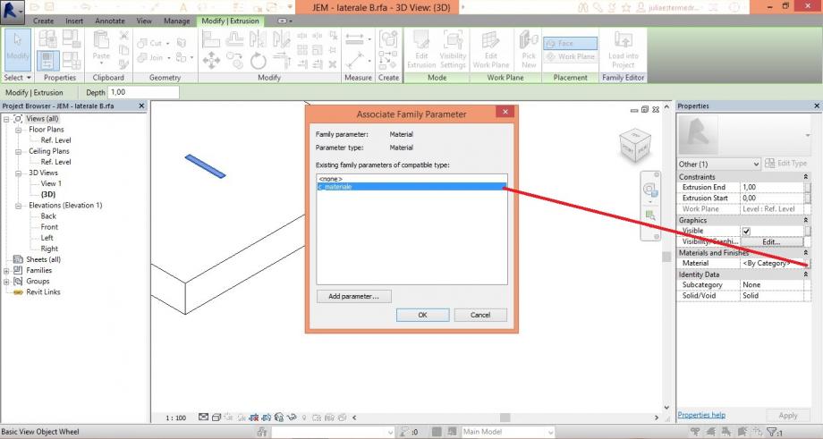
3. Ho fatto le associazione di ogni parametri alle misure corrispondenti, sciegliendo la opzione "inst.ance" con eccezione del parametro materiale che è stato creato nella opzione "type", perché dopo lo cambierò tra i materiali di legno e metallo.
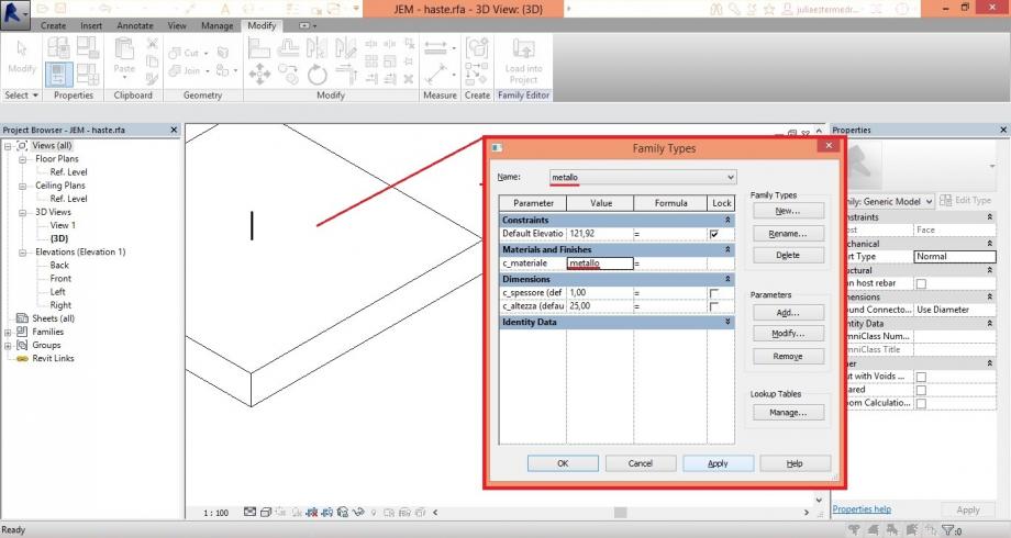
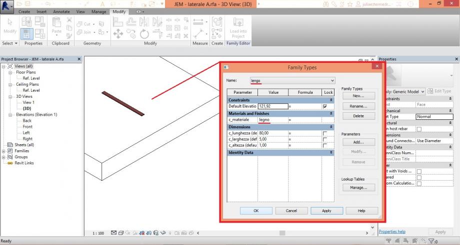
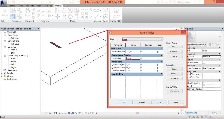
4. L'idea è fare una scatola che possa essere modificata la dimensione cambiando solo un parametro, per esempio se altero la dimensione "x" della base automaticamente il lato collegato anche cambia per la stessa misura, così come l'perazione inversa deve funzionare. Quindi ho utilizzato lo stessi parametri in ogniuno pezzo.
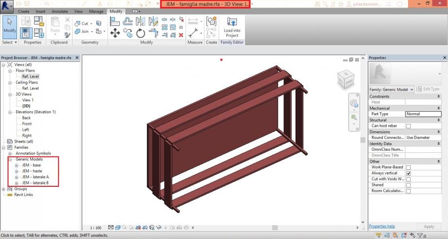
5. Dopo ho scaricato tutti i componenti sull'archivio "famiglia madre" (generic model)...
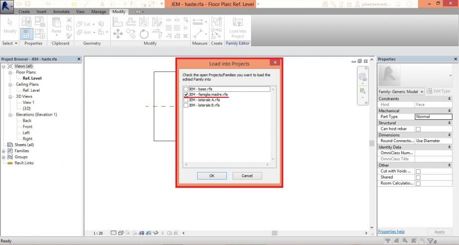
6....e ho montato la scatola.
7. Ma non ho riuscito collegare un pezzo al piano di riferemento di forma che muovendo il piano muoverebbe il pezzo.
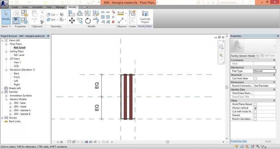
8. ho contiunato a lavorare, forse nell'archivio di progetto potrei fare la modificazione.
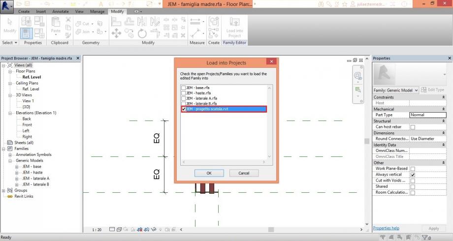
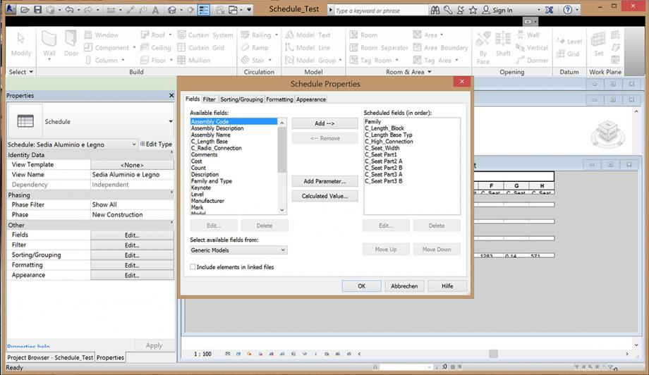
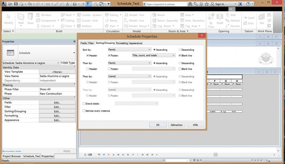
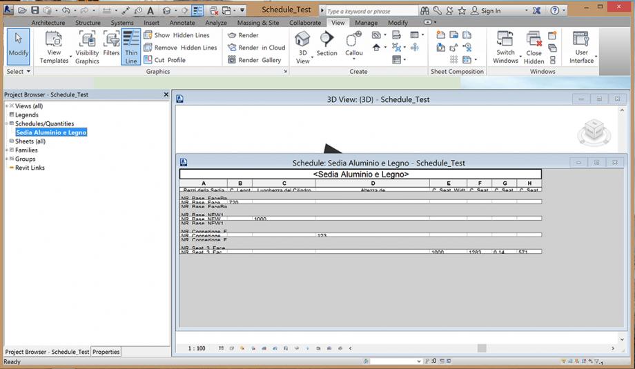
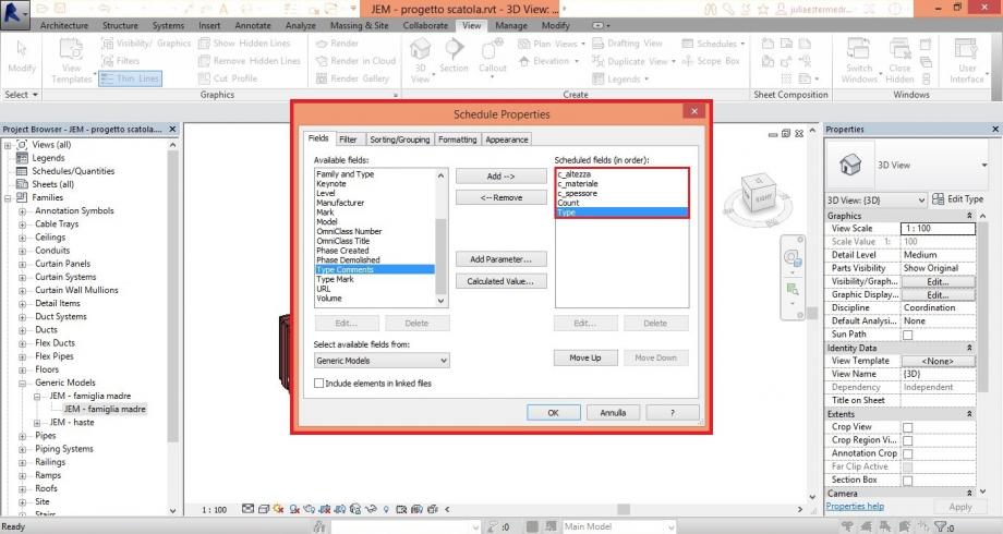
9.Dopo scaricato il archivio volevo vedere come era il funzionamento della tabela. Per vederla ho scelto New schedule>>generic models>>...
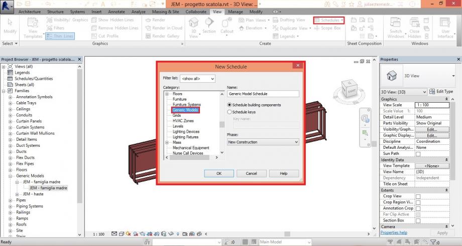
10. Ho aggiunto le proprietà dei parametri condivisi, più "count e type).
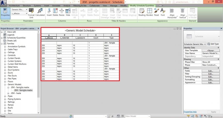
11. Prima non riusciva fare la visualizzazione completa.
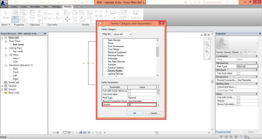
12. Ho cambiato l'opzione su family category and parameters>> "shared" in ciascuno pezzo.
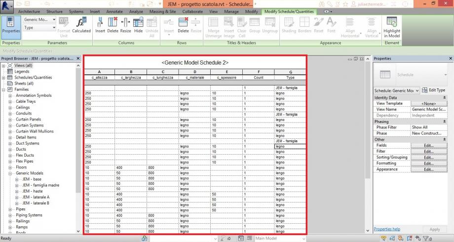
Adesso non riesco a modificare ninente dentro della tabela. Sembra che tutti lo spazi sono bloccati.
Dom, 30/11/2014 - 00:07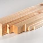 andrea piattella
Ven, 28/11/2014 - 16:18
andrea piattella
Ven, 28/11/2014 - 16:18
As for the second delivery i started opening a NEW family - GENERIC METRIC MODEL FACED BASED- OPEN
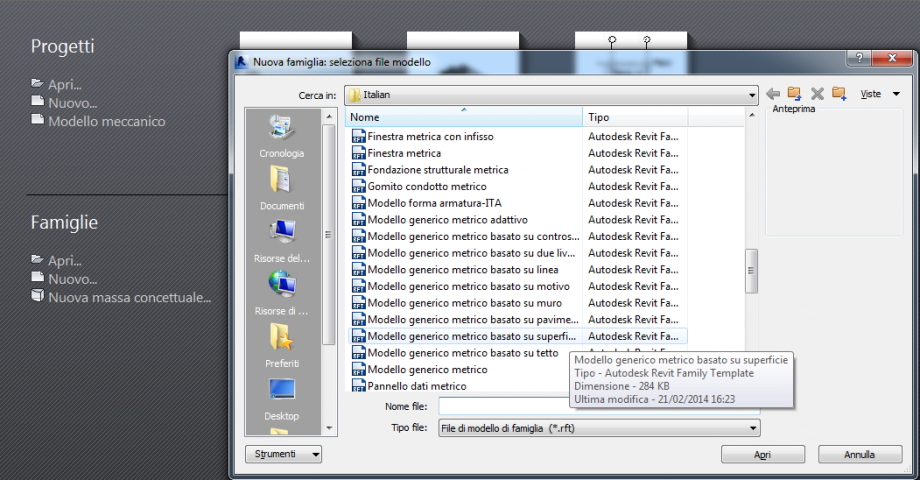
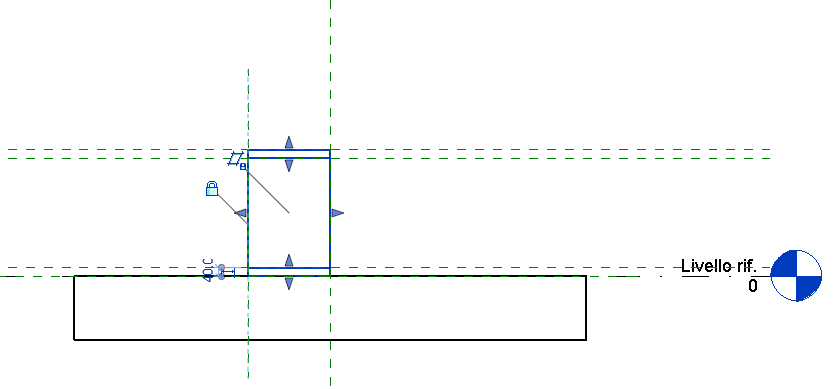
I opened this new file and I decided the elevation to realized the section of my element. Than I drew the REFERNCE PLANE( each one for each bord of the object )
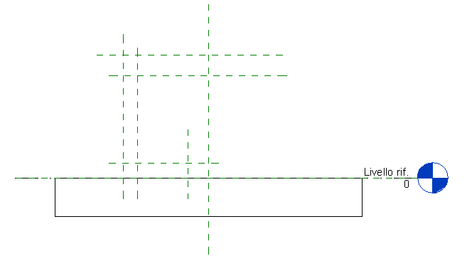
Than I assign the dimension to all the distances
I created the parameters that i needed for each distances. Than once I finished and closed the family's window, I clicked one by one the distances and I assigned for each one the parameters.
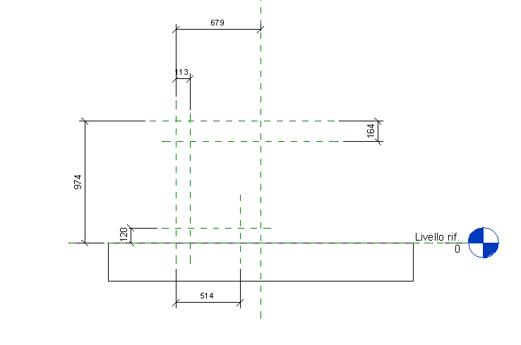
Than I modified the parameters with the design mesures.

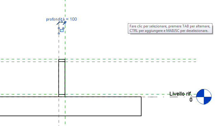
After that I exstruded my geometry with the command CREATE EXTRUSION.
I changed elevation to define the width of the object creating a new REFERENCE PLANE and locked it to the extrusion.
I created also a new parameter for the width of the object and I assigned to it.
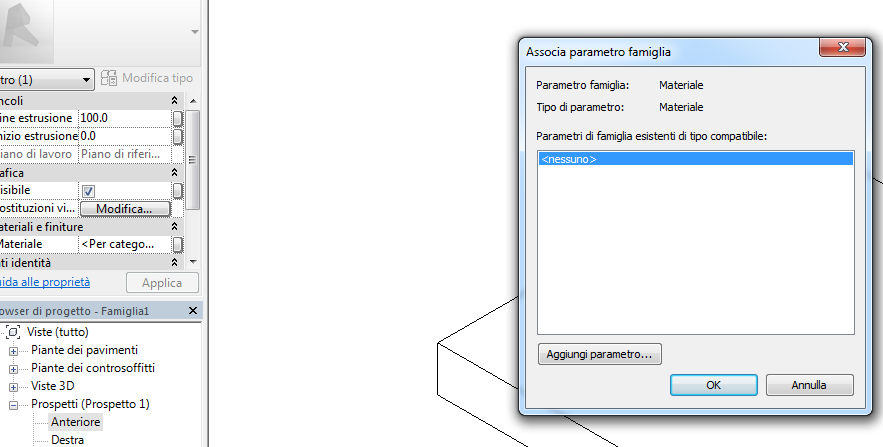
To assigne the material to the extrusion I selected the property of the family and I created a new parameter for the material I wanted.
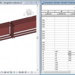
I placed the families of the components of my object in the mother family .
I Loaded the families and I changed their parameters. There's a window on the left with all the families, I clicked on the family that I wanted to change.