


 Matteo Cucciniello
Mer, 05/02/2025 - 22:58
Matteo Cucciniello
Mer, 05/02/2025 - 22:58
Buongiorno, questo è stato il procedimento per la realizzazione della terza consegna
1. Creo una nuova famiglia su revit, scelgo un modello face based
 2. seguendo i procedimenti delle passate consegne disegno un profilo associato a dei paramentri così da poter modficare il profilo solo dai valori numerici associati


 3. salvo la famiglia come "CMT - seduta" e dopodichè creo un nuovo file famiglia selezionando "curtain wall panel"
 4. importo la famiglia "CMT - seduta" e inserisco il profilo. Disegno un nuovo profilo accoppiato direttamente in questo file. Associo il nuovo profilo a un parametro condiviso di istanza in modo da poterlo modificare in seguito. Salvo il file della famiglia come "CMT - telaiocurtain"

5. creo un file progetto e disegno, aiutandomi con dei piani di riferimento, un elemento muro. Importo nel progetto la famiglia creata in precedenza. Dopodiche, seleziono l'elemento muro e nelle sue proprietà modifico il tipo. Seleziono Curtain Wall e nel pannello proprietà sotto la voce "pannello di facciata" seleziono la famiglia importata e la associo. Per determinare la scansione dei telai sotto la voce griglia verticale seleziono il "distanza fissa" e indico un valore numerico.


6. Apro un abaco che mi riporti il parametro condiviso, così da poter modificare parametricamente la dimensione delle sedute.
 7. imoosto una camera e seleziono la vista

Mer, 05/02/2025 - 23:29
 Giulia Anzellotti
Mer, 05/02/2025 - 17:31
Giulia Anzellotti
Mer, 05/02/2025 - 17:31
buongiorno, ho provato ad allegare le imamgini al testo ma nn mi e stato possibie, per questo motivo ho creato una nuova consegna ma con i file allegati
Mer, 05/02/2025 - 17:35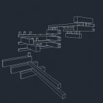 Giulia Anzellotti
Mer, 30/10/2024 - 16:00
Giulia Anzellotti
Mer, 30/10/2024 - 16:00
Buongiorno,
questo è il mio post per spiegare il flusso di lavoro usato nella prima consegna (risistemata)
- per realizzare il progetto, ho aperto l'applicazione di Revit e ho cliccato Family>New Family>Metric Genneric Model- ho realizzato 2 nuovi piani, uno verticale e uno orizzontale. Nella vista laterale ho realizzato un uletriore piano orizzontale parallelo alla linea di terra.
- Ho inserito due nuove quote in pianta e una in alzato, per misurare la distanza tra gli assi principali presenti di default nella schermata con i nuovi piani creati
- Poi con il comando Family Types vado a creare 3 nuovi parametri altezza, lunghezza e spessore
- Una volta creati i parametri li collego alle quote e lo faccio assegnando l'etichetta, successivamente tramite il comando estrusione realizo un parallelepipedo, che poi collego e vincolo tramite i lati ai piani realizzati sia in pianta che nella vista laterale.
- A qusto punto la prima famiglia creata avrà le caratteristiche assegnate e tre tipologie diverse (A,B e C)
- Una volta create le famiglie, apro un nuovo progetto in Revit e le carico al suo interno, stabilendo per ogni ggetto a quale tipo di famiglia appartiene
- una volta stabilita il tipo di famiglia a cui appartiene ogni oggetto, con l'aiuto del comando "piano di riferimento" mi creo la mia composizione
-Tramite il comando camera definisco in pianta la posizione della vista prospettica
-
-dalla vista ho completato la composizione
 Francesco Di Gennaro
Mer, 05/02/2025 - 14:32
Francesco Di Gennaro
Mer, 05/02/2025 - 14:32
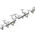
Il progetto "Astroforesta" è nato dalla volontà di creare uno spazio che potesse fruire come luogo di ombreggiamento e punto di raccolta per i residenti di Torrevecchia. La forma della struttura e il design è modulare e leggero, offrendo sedute ombreggiate con una connessione fra le panchine già esistenti e quelle in legno. La forma ad asterisco è stata generata dalla forma primordiale dell'albero, quindi abbiamo voluto creare un legame fra ciò che è artificio e ciò che invece è riconducibile alla natura. La composizione da noi creata simula un'area boschiva volta a coinvolgere tutta la comunità di torrevecchia e a migliorare la qualità degli spazi urbani; questo intervento ha come obiettivo non solo creare spazi pubblici aperti di socialità, ma anche quello di divenire un innesco che farà da catalizzatore-sociale andando coinvolgere tutti i residenti di Torrevecchia. Sebbene il progetto sia pensato per una limitata quantità di materiali di recupero, siamo riusciti a minimizzare la lavorazione e la quantità del materiale massimizzando la sostenibilità economica.
Francesco Di Gennaro, Alessia Notarangelo, Olivia Steels, Elisa Vit
Mer, 05/02/2025 - 15:26 Justine Musielinski
Mer, 05/02/2025 - 14:01
Justine Musielinski
Mer, 05/02/2025 - 14:01
Create -> Family -> Metric Curtain Wall Panel

Family Type -> Shared Parameters -> S_Length, S_Width, S_Height 
File -> Open Family -> Load into Family

Align the solid to the reference planes (the solid should follow when a reference plane is moved)


In Family Type -> New Parameter -> "S_L" -> Select "Type"
Click on the solid in the family -> In Properties -> S_Length -> Click on the square icon -> Assign S_L


Create a new project -> Construction Template
Create an architectural wall -> In Properties set it to "Curtain Wall"


Align the wall with the "Base TO" level
In Properties -> Layout -> Fixed Distance -> Spacing 1000

Load the Wall Panel Project

In the South Elevation -> Click on the wall -> Type -> In Curtain Wall Panel set the family

In the family’s exterior elevation -> Create -> Model Line -> Align
In the family -> Add -> New Parameter -> Name it Line -> Data Type "Yes/No" ->


Load into the project
In the exterior view -> Click on the family -> In Properties click on the square next to "Visible" -> Load into the project
In the project -> Type Properties -> Line (checked to appear, unchecked to disappear)

Load the family into the other family
Place the elements -> Align to the reference planes -> Load into the project


Go into the family -> Left Elevation view -> Add a reference plane -> Import an element from the family -> Align to the reference plane -> Load into the project


Go into the schedule -> Curtain Wall Panel -> S_Height -> Modify the heights

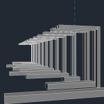
Here is the composition I made during the class  and then the more elaborate one
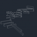

another example of assembly possible by following all these steps

Mer, 05/02/2025 - 14:06