 Leonardo Deidda
Gio, 06/02/2025 - 15:41
Leonardo Deidda
Gio, 06/02/2025 - 15:41
Ecco i passaggi della mia terza consegna:
1) Creo una nuova famiglia e seleziono "Metric Curtain Wall Panel"

2) Allineo una famiglia già creata ai riferimenti, in questo caso ho utilizzato un "Metric Generic Model" di forma allungata 

3) Utilizzo 3 famiglie differenti di "Metric Generic Model Facebased"


4) Compongo il modulo singolo che andrò a utilizzare


5) Apro un file di progetto e posiziono un muro:

6) Seleziono la categoria "Curtain Wall" con edit type:

7) Dalle proprietà di questo importo la famiglia del modulo singolo e modifico la griglia orizzontale e verticale per ottenere il risultato desiderato:

8) copio e sposto l'oggeto per definire lo spazio che andrà ad inquadrare


 Federico Liquori
Gio, 06/02/2025 - 15:33
Federico Liquori
Gio, 06/02/2025 - 15:33
progetto TVB Caracciolo Carozza Cosco Filesi Liquori | bim.rootiers.it
Gio, 06/02/2025 - 15:36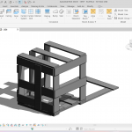 Federico Liquori
Gio, 06/02/2025 - 15:15
Federico Liquori
Gio, 06/02/2025 - 15:15
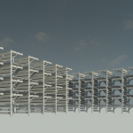
Come prima cosa si crea una famiglia di "curtain wall panel' e l'ho usata per assemblare la struttura sfruttando i diversi posizionamenti delle assi


 Federico Liquori
Gio, 06/02/2025 - 14:07
Federico Liquori
Gio, 06/02/2025 - 14:07
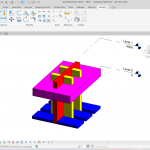
Per questo progetto ho immaginato una struttura ad incastro usando due famiglie differenti e giocando con le proporzioni. Ho utilizzato il colore per differenziare le varie parti del mio progetto utilizzando colori caldi per gli elementi che si sviluppano in verticale, e colori freddi per quelli che si sviluppano in orizzontale. La differenza di colore varia anche in base all'orditura dell'elemento.