 Renato Manna
Gio, 06/02/2025 - 16:24
Buongiorno professore, per la seconda consegna riprendo i file della prima esercitazione
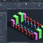
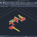
Per poter proseguire, creo una Tabella in cui metto in evidenza tutte le proprietà del progetto, quali famiglia, tipo e parametri condivisi.
Successivamente, tramite "Visibility/Graphic Overrides" creo una tavolozza di colori e il filtro che mi permetterà in base al nome del tipo di colorare gli elementi presenti nella composizione


 Giulia Anzellotti
Gio, 06/02/2025 - 16:24
Buongiorno,
la mia idea progettuale è la creazione di una composizione di elementi sfalsa la su più livelli ma differenziandoli per colore in base al livello dove sono collocati basandomi sul progetto iniziale ( mi riferisco alla prima consegna)
- Ho creato poi una Schedule, una tabella delle proprietà del progetto, nella quale ho evidenziato la famiglia, il tipo e parametri condivisi


-"Visibility/Graphic Overrides" (che si apre anche cliccando VG sulla tastiera) creo una tavolozza di colori e il filtro che mi permetterà in base al commento di colorare gli elementi presenti nella composizione
 -In ‘Visibility/Graphic Overrides’ creo una tavolozza di colori e associo ad ogni componente un colore

Gio, 06/02/2025 - 16:35
 LC
Gio, 06/02/2025 - 16:13
http://bim.rootiers.it/node/4274
Inizialmente abbiamo immaginato di creare un elemento che riprendesse, ma al contempo semplificasse in forme geomentriche regolari, l'andamento organico della panchina-balaustra di Parc Güell a opera di Antoni Gaudì, caratterizzata da un continuo e ondoso succedersi di sporgenze e rientranze che consentono ai visitatori di riunirsi in piccole unità di socializzazione e interagire tra di loro.
Una prima bozza di progetto si basava sulla forma ottagona, la forma più simile al cerchio che potesse essere realizzata con il materiale in legno a disposizione. Il progetto prevedeva delle sedute ottagonali alternate da tavoli rettangolari e coperte da una pensilina leggera.
Vista la rigidità della struttura, abbiamo deciso di separare i moduli, creando piccole unità, in cui la forma ottagona è ripresa anche nel prospetto laterale, andando a fondere la seduta con la copertura inclinata. Avevamo immaginato anche diverse composizioni con lo stesso modulo.
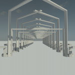
Infine abbiamo deciso di spezzare le singole sedute e contrapporle, unendole con delle aste che ne permettessero l'unità e la stabilità; tale modulo lo abbiamo ripetuto fino a formare il disegno di uno spazio aperto, permeabile e dinamico, in cui le stesse aste di connessione sono diventate delle passerelle, dove ci si può anche sedere.Il nome del progetto 'New Bronx' nasce con l'intento di riqualificare non solo l'area, ma anche l'immagine del luogo, con l'obiettivo di non cancellare il passato ma di creare la speranza per un Nuovo futuro.
Gio, 06/02/2025 - 16:18 Dimitri Della Casa
Gio, 06/02/2025 - 14:26
In seguito al sopralluogo all'interno del Bronx di Torrevecchia la nostra idea era quella di valorizzare l'area asfaltata del cortile a nord-est cercando di creare una struttura circolare nella quale gli abitanti (e non) potessero interagire tra loro e vivere collettivamente lo spazio. 
Inizialmente abbiamo immaginato di creare un elemento che riprendesse, ma al contempo semplificasse in forme geomentriche regolari, l'andamento organico della panchina-balaustra di Parc Güell a opera di Antoni Gaudì, caratterizzata da un continuo e ondoso succedersi di sporgenze e rientranze che consentono ai visitatori di riunirsi in piccole unità di socializzazione e interagire tra di loro.

Una prima bozza di progetto si basava sulla forma ottagona, la forma più simile al cerchio che potesse essere realizzata con il materiale in legno a disposizione. Il progetto prevedeva delle sedute ottagonali alternate da tavoli rettangolari e coperte da una pensilina leggera.


Vista la rigidità della struttura, abbiamo deciso di separare i moduli, creando piccole unità, in cui la forma ottagona è ripresa anche nel prospetto laterale, andando a fondere la seduta con la copertura inclinata. Avevamo immaginato anche diverse composizioni con lo stesso modulo. Infine abbiamo deciso di spezzare le singole sedute e contrapporle, unendole con delle aste che ne permettessero l'unità e la stabilità; tale modulo lo abbiamo ripetuto fino a formare il disegno di uno spazio aperto, permeabile e dinamico, in cui le stesse aste di connessione sono diventate delle passerelle, dove ci si può anche sedere.Il nome del progetto 'New Bronx' nasce con l'intento di riqualificare non solo l'area, ma anche l'immagine del luogo, con l'obiettivo di non cancellare il passato ma di creare la speranza per un Nuovo futuro.
Gio, 06/02/2025 - 16:12
 Andrea Loddo
Gio, 06/02/2025 - 15:06
A seguito i miei passaggi eseguiti per la realizzazione della Terza consegna:
- Creo una nuova famiglia, selezionando dalla cartella "English" il template nominato "Metric Curtain Wall Panel";
- A questo punto si può o importare una famiglia come creare una nuova estrusione, io procedo con questa seconda opzione;

- Importo un'altra famiglia face based creata in precedenza, in questo caso "LDD - Famiglia appiccicosa.rfa";

- Usando i vari tipi a mia disposizione, creo una composizione;

- Creo un nuovo progetto ed ci importo la famiglia creata poco fa
- Aggiungo nel progetto un muro di tipo "curtain wall"

- Apro la scheda "Edit Type" del curtain wall e modifico il "curtain panel" affinchè sia la famiglia appena importata

- Dopo aver modificato il "curtain panel" modifico lo spacing fino ad ottenere un risultato soddisfacente;


