


 Giorgiaa Filesi
Gio, 06/02/2025 - 16:50
Giorgiaa Filesi
Gio, 06/02/2025 - 16:50
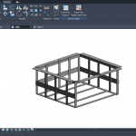
Per iniziare, ho creato tre famiglie di curtain wall panel. Successivamente le ho assemblate insieme, andando a creare una struttura.


 Gaia Barbis
Gio, 06/02/2025 - 16:51
Gaia Barbis
Gio, 06/02/2025 - 16:51
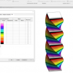
 Elenco i passaggi per la creazione della composizione n.3:
• Dall'interfaccia iniziale di Revit, creo una nuova famiglia selezionando, quindi, il template "Metric generic model".
• Creo due piani di riferimento, uno verticale ed uno orizzontale, digitando sulla tastiera "rp" o cliccando dal menù "Create" l'icona corrispondente a Reference Plane.
• Da "Annotate" seleziono la quota lineare e la inserisco alla distanza tra i piani di riferimento creati e quelli di default (verifico ogni volta che la quota funzioni modificando la distanza tra gli assi).
• Da "Create" clicco su "Extrusion", seleziono il rettangolo in "Draw" e creo il rettangolo facendo attenzione a non disegnarlo (per ora) sui piani di riferimento.
• Da "Modify" in "Properties" seleziono "Family Types" per creare i miei parametri (altezza, lunghezza, spessore). Clicco su "New Parameter", seleziono "Family Parameter" in "Parameter Type", Assegno un nome e seleziono "Type" in "Parameter Data".
Ai parametri creati assegno dei valori; perchè voglio che la base dei miei solidi sia quadrata, assegno al parametro lunghezza la stessa grandezza del parametro spessore digitando in formula "=spessore". Creo tre tipi verticali (tutti con differente altezza tra loro ma solo il meno alto anche con spessore e lunghezza minori).
• Per "collegare" i parametri creati e il disegno assegno i parametri alle quote create in precedenza cliccandoci sopra e selezionando in "Label" il parametro corrispondente.
• Digitando "al" o selezionando da "Modify" il comando "Align" allineo i quattro lati (in pianta) del rettangolo ai quattro assi di riferimento prestando sempre attenzione a chiudere il lucchetto e bloccare l'allineamento (in questo modo, modificando le quote degli assi, si modificherà anche il solido e, viceversa, modificando i parametri del solido, si sposteranno anche gli assi).
• Apro la vista "Front", creo un nuovo piano di riferimento ecgli assegno il parametro "altezza" e allineo il lato del solido.
• Avendo creato parametri tipo, creo una nuova famiglia.
• creo i miei parametri ma, questa volta per "altezza" e "spessore" seleziono "Istance" in "Parameter Data" al fine di creare un 'unicum'. Creo due oggetti "piastra" entrambi con dimensioni non legate da nessun tipo di proporzione (lascio quindi tutti i campi "Formula" vuoti).
• Clicco in alto a sinistra su "File", clicco su "New" > "Project" .
• Carico entrambe le famiglie create cliccando su "Insert" > "Load Family" .
• Nel "Project Browser", sotto la voce "Families", in "Generic Models" trovo le famiglie create e caricate.
• Trascino dal menù i solidi cosicché li posso posizionare sul piano di lavoro e posso creare la mia composizione.
• Clicco sull'icona della casetta in alto e poi su "Camera" posso posizionare il punto di vista.
 Gaia Barbis
Gio, 06/02/2025 - 16:49
Gaia Barbis
Gio, 06/02/2025 - 16:49
Creazione della famiglia – Pianta e Prospetto
- Aprire Revit e dalla pagina Family aprire il file Generic Model
- Creare 2 piani di riferimento verticali e 2 piani di riferimento orizzontali con Reference Plan ad una distanza di 4000 x 4000
- Assegnare due quote lineari ai piani
- Creare l’estrusione della pianta allineandola ai piani di riferimento e bloccandola ad essi con il lucchetto
- Impostare la visualizzazione Shadow

 Giorgiaa Filesi
Gio, 06/02/2025 - 16:04
Giorgiaa Filesi
Gio, 06/02/2025 - 16:04
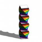
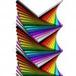
Per questo progetto ho pensato ad una composizione a doppia spirale, usando 5 famiglie differenti e variando le dimensioni, ma mantenedo lo stesso rapporto tra spessore e lunghezza. Come colore principale ho scelto il blu, applicando ad ogni famiglia una sfumatura diversa.


 Gaia Barbis
Gio, 06/02/2025 - 16:36
Gaia Barbis
Gio, 06/02/2025 - 16:36
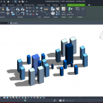
Elenco i passaggi svolti per la costruzione della composizione n.1:
• Dall'interfaccia iniziale di Revit, creo una nuova famiglia selezionando, quindi, il template "Metric generic model".
• Creo due piani di riferimento, uno verticale ed uno orizzontale, digitando sulla tastiera "rp" o cliccando dal menù "Create" l'icona corrispondente a Reference Plane.
• Da "Annotate" seleziono la quota lineare e inserisco la quota della distanza tra i piani di riferimento creati e quelli di default (verifico ogni volta che la quota funzioni modificando la distanza tra gli assi).
• Da "Create" clicco su "Extrusion", seleziono il rettangolo in "Draw" e creo il rettangolo facendo attenzione a non disegnarlo (per ora) sui piani di riferimento.
• Da "Modify" in "Properties" seleziono "Family Types" per creare i miei parametri (altezza, lunghezza, spessore). Clicco allora su "New Parameter", seleziono "Family Parameter" in "Parameter Type", Assegno un nome e seleziono "Type" in "Parameter Data".
Ai parametri creati assegno dei valori; perchè voglio che la base dei miei solidi sia quadrata, assegno al parametro lunghezza la stessa grandezza del parametro spessore digitando in formula "=spessore". Creo tre tipi verticali (tutti con differente altezza tra loro ma solo il meno alto anche con spessore e lunghezza minori).
• Per "collegare" i parametri creati e il disegno assegno i parametri alle quote create in precedenza cliccandoci sopra e selezionando in "Label" il parametro corrispondente.
• Digitando "al" o selezionando da "Modify" il comando "Align" allineo i quattro lati (in pianta) del mio rettangolo ai quattro assi di riferimento prestando sempre attenzione a chiudere il lucchetto e, quindi, bloccare l'allineamento (in questo modo, modificando le quote degli assi, si modificherà anche il solido e, viceversa, modificando i parametri del solido, si sposteranno anche gli assi).
• Apro la vista "Front", creo un nuovo piano di riferimento e gli assegno il parametro "altezza" e allineo il lato del solido.
• Avendo creato parametri tipo, creo una nuova famiglia.
• creo i miei parametri ma, questa volta, nel creare i parametri "altezza" e "spessore" seleziono "Istance" in "Parameter Data" al fine di creare un 'unicum'. Creo due oggetti "piastra" entrambi con dimensioni non legate da nessun tipo di proporzione (lascio quindi tutti i campi "Formula" vuoti).
• Clicco in alto a sinistra su "File", clicco su "New" > "Project" .
• Carico entrambe le famiglie create cliccando su "Insert" > "Load Family" .
• Nel "Project Browser", sotto la voce "Families", in "Generic Models" trovo le famiglie create e caricate.