
 Giulia Anzellotti
Gio, 06/02/2025 - 21:07
Giulia Anzellotti
Gio, 06/02/2025 - 21:07
Ecco i passaggi della mia terza consegna:
-Creo una nuova famiglia e seleziono "Metric Curtain Wall Panel"

-Allineo una famiglia già creata ai riferimenti, in questo caso ho utilizzato un "Metric Generic Model" di forma allungata
-Allineo una famiglia già creata ai riferimenti, in questo caso ho utilizzato un "Metric Generic Model" di forma allungata
 -Compongo il modulo singolo che andrò a utilizzare


-A questo punto selezionando il muro e andando prima su “edit type”,successivamente sulla voce “curtain panel” ed infine selezionando la famiglia appena importata (in questo caso da me denominata “pannello di facciata"), il programma andrà a creare una ripetizione regolare dei nostri elementi.

-A questo punto starà alla fantasia di ognuno di andare a creare una qualsiasi forma geometrica che si basi sulla variazione delle dimensioni delle famiglie appena importate e sulla variazione delle ripetizioni.


Gio, 06/02/2025 - 21:19
 Giulia Anzellotti
Gio, 06/02/2025 - 21:07
Giulia Anzellotti
Gio, 06/02/2025 - 21:07
Ecco i passaggi della mia terza consegna:
-Creo una nuova famiglia e seleziono "Metric Curtain Wall Panel"
-Allineo una famiglia già creata ai riferimenti, in questo caso ho utilizzato un "Metric Generic Model" di forma allungata
-Allineo una famiglia già creata ai riferimenti, in questo caso ho utilizzato un "Metric Generic Model" di forma allungata
-Compongo il modulo singolo che andrò a utilizzare
-A questo punto selezionando il muro e andando prima su “edit type”,successivamente sulla voce “curtain panel” ed infine selezionando la famiglia appena importata (in questo caso da me denominata “pannello di facciata"), il programma andrà a creare una ripetizione regolare dei nostri elementi.
-A questo punto starà alla fantasia di ognuno di andare a creare una qualsiasi forma geometrica che si basi sulla variazione delle dimensioni delle famiglie appena importate e sulla variazione delle ripetizioni.
Gio, 06/02/2025 - 21:19
 Baptiste Harang
Gio, 06/02/2025 - 20:46
Baptiste Harang
Gio, 06/02/2025 - 20:46
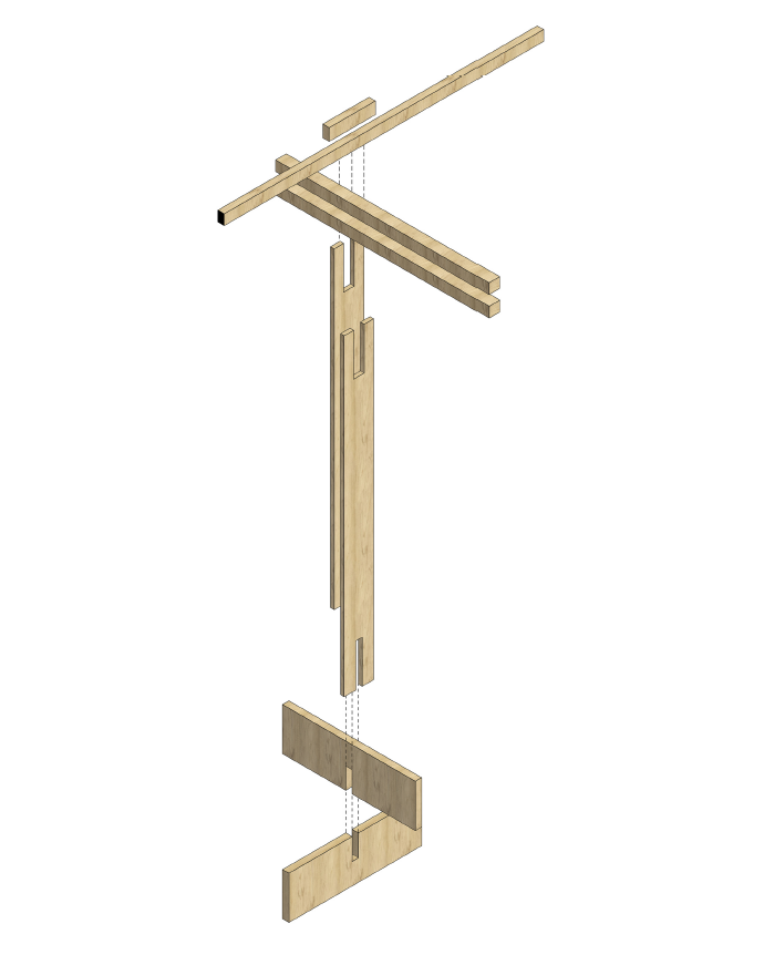
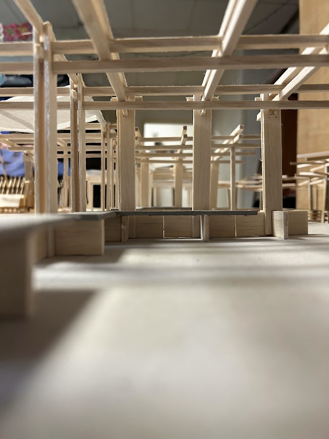
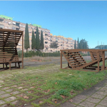
For our project, we chose to establish ourselves around the existing benches near the football field. This decision to rely on the existing benches guided our choices from the very beginning, as we used them as the backbone of our project.
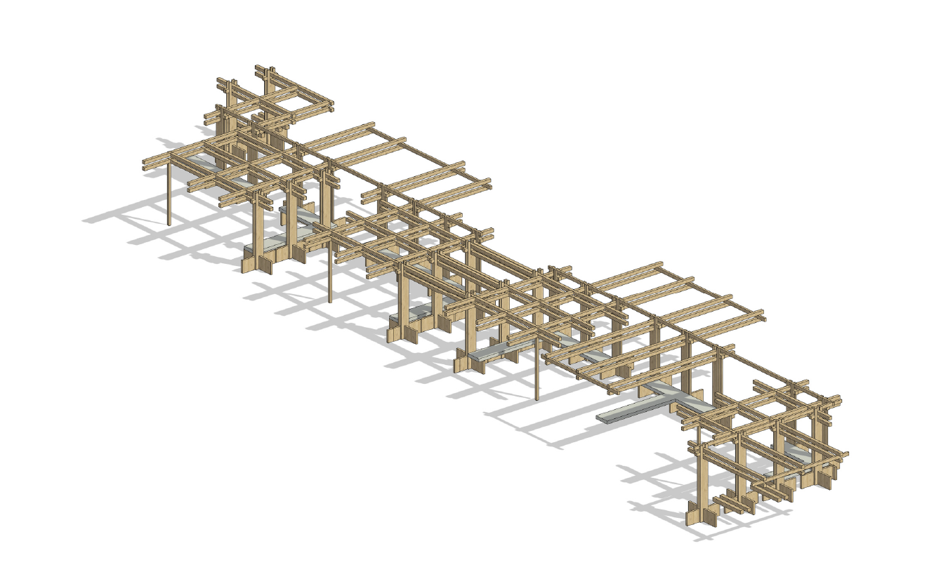
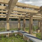
We aimed to create shaded areas produced by the intersection of our porticos. This interplay of crossing porticos generates different spaces, varying in openness and shade. The goal is also to facilitate construction, particularly with two modules: one consisting of laminated wooden posts and the other featuring intersecting wooden beams. These two modules can be built separately and then assembled afterward.
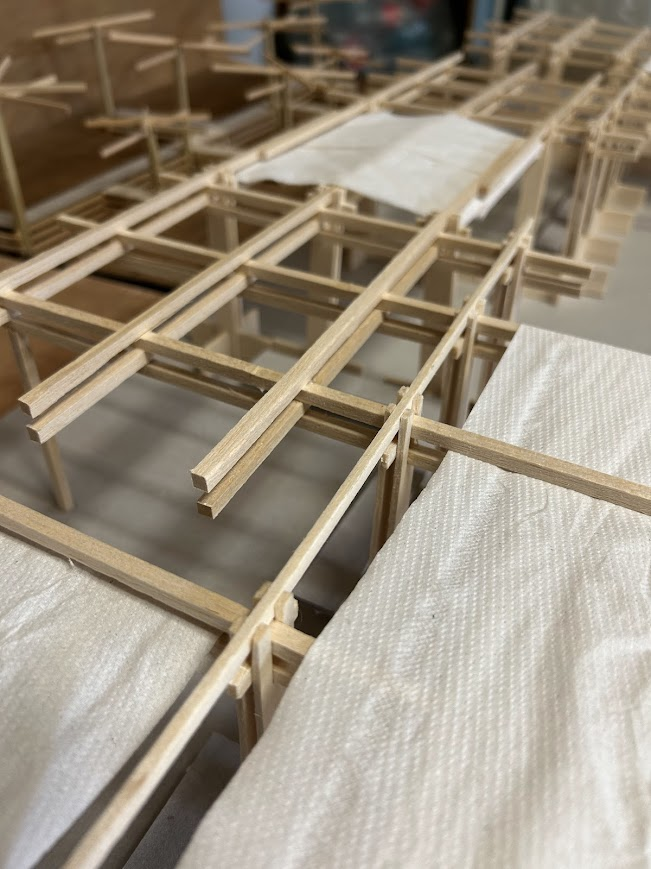
The overall shape echoes that of the benches while incorporating openings of different sizes to encourage residents to pass through the structure. Some of the wooden assemblies are covered with fabric to provide additional shade.
Thus, the project relies heavily on existing elements to create a space for movement and social interaction. Ultimately, the goal is to develop functional spaces that are open to everyone.