


 ferraro_perrotti
Dom, 26/04/2015 - 13:02
ferraro_perrotti
Dom, 26/04/2015 - 13:02
PART1
- 1Step: Run the Program

- 2Step: Open the previous Project
Open the previous Project in order to work on it.
in thic case Vigna ciollo.rvt;

It will open the previous project, so we are ready to work on it;

- 3Step Preparing the project in order to draw on it
First of all we have to put the different levels at the right odds to draw correctly the balconies and windows.
Clicking on evry single level we modify the elevation;

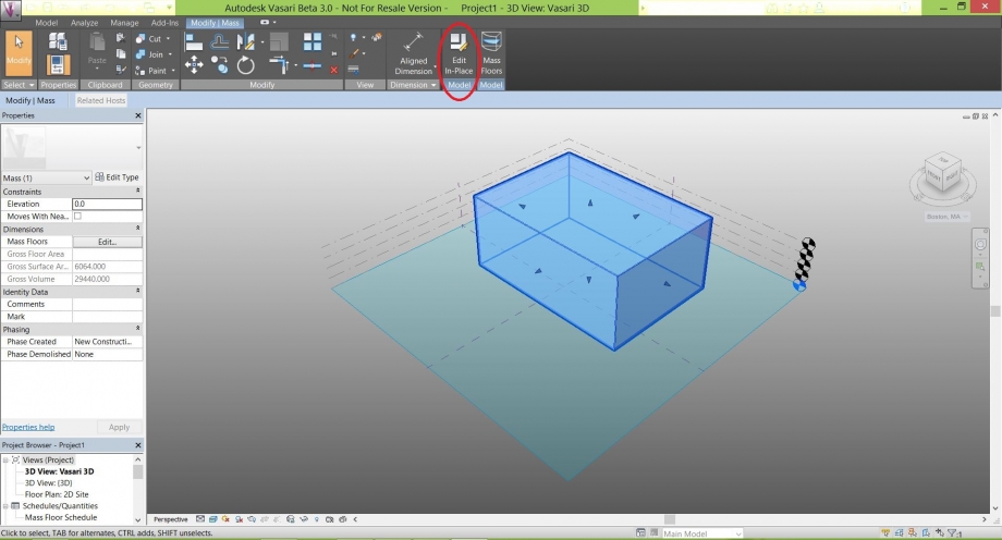
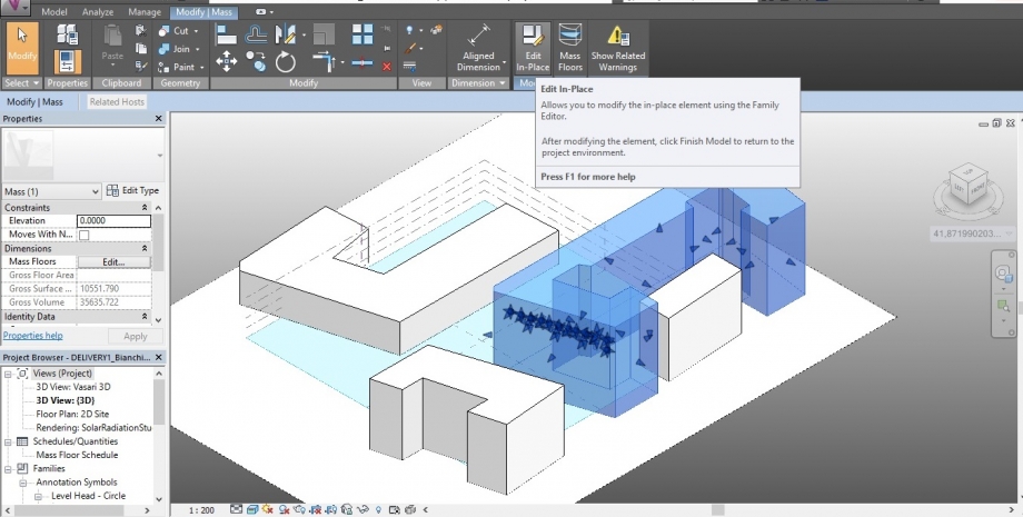
After that we have to select all the buildings as in the figure;

Go to Mass Floor and Click on it.

It will open a table with all the Mass Floors;
In this case with 5 Levels;
We have to show all the Levels to have the visible elevation on the project , so we can start to draw on it;
Click on all the Levels, than Click OK;

Now the orange lines identify the different elevations;

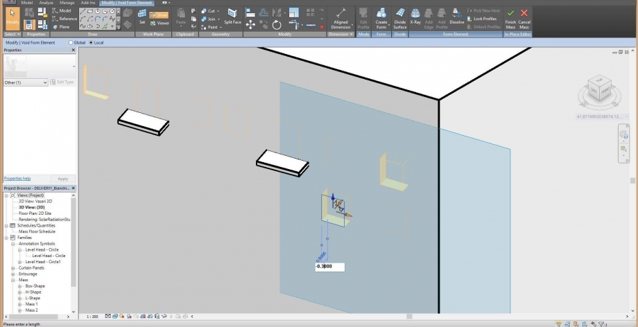
- 4Step Draw windows and Balconies
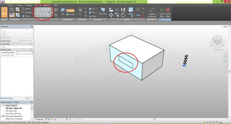
Select the first building;

To work on it Go to Edit In Place;

Now we are ready to draw all the windows and Balconies;
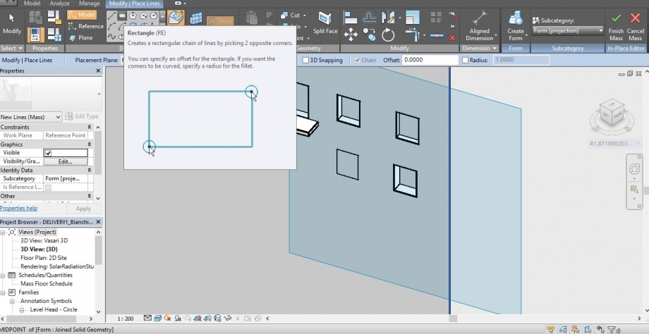
Select one face;

Go to Modify Place Lines and Click on Rectangle in order to draw the balconies;

Draw the floor of the balcony;

Modify thw two dimensions with the right measures;


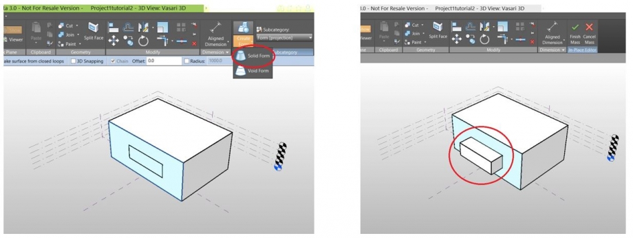
Select the Rectangle and Drag to make the 3D extrusion;

Now, as we can see, we have obtain the first balcony;

We use the same passages to Draw the other balconies;

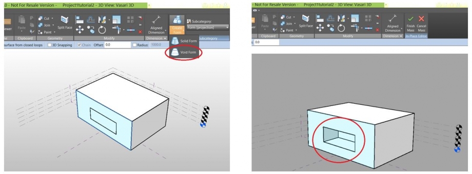
Draw the windows Go to Model, Rectangles and Draw the window;

Select the Rectangle, Go to Create Form and Click on Void Form and you will have the window;
 Repeat the same passages to Create the rest of the Windows;

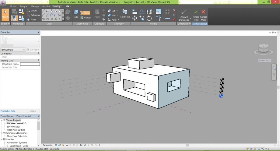
Draw the Balconies on the other building;

Draw just two Windows also on the other building;

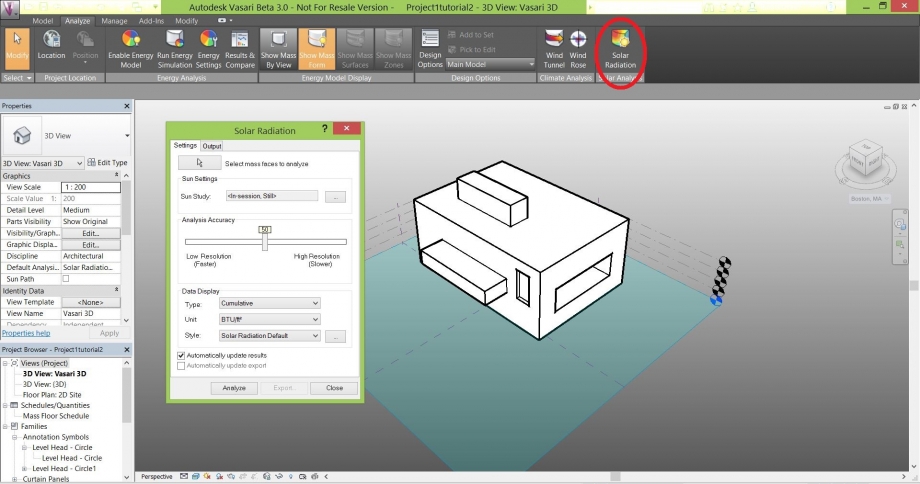
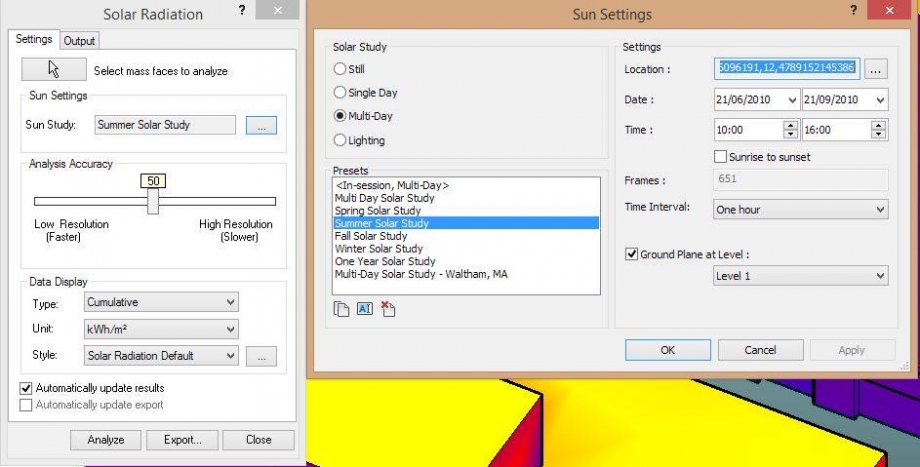
- 5Step Solar Radiation
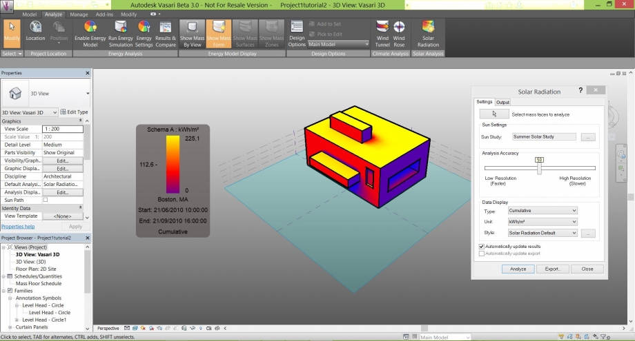
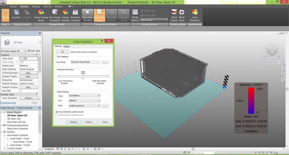
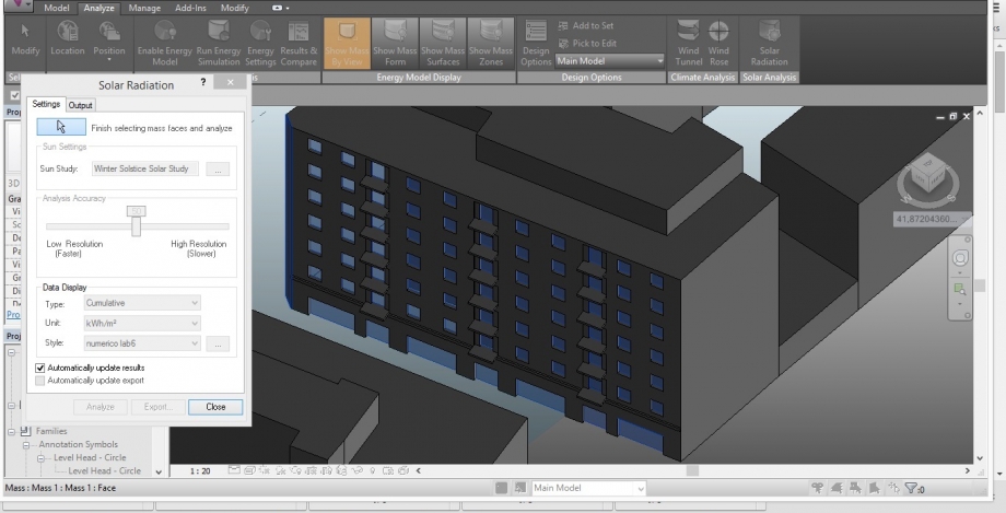
Finish the Mass form and clicl on Solar Radiation;

It will open a table of Solar Radiation that it has to be modified;

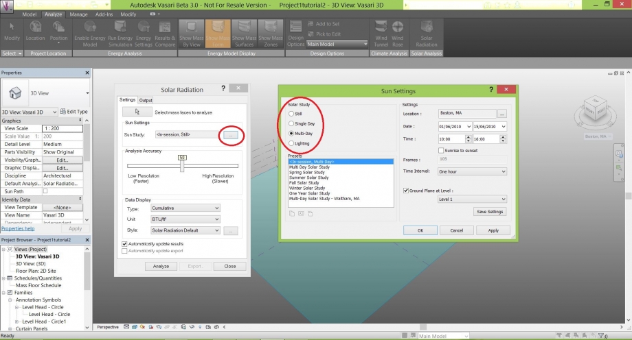
Click on ... at the right of Spring Equinox;

Modify the solar Study click on Multi-Day ans Summer Solstice, for example;

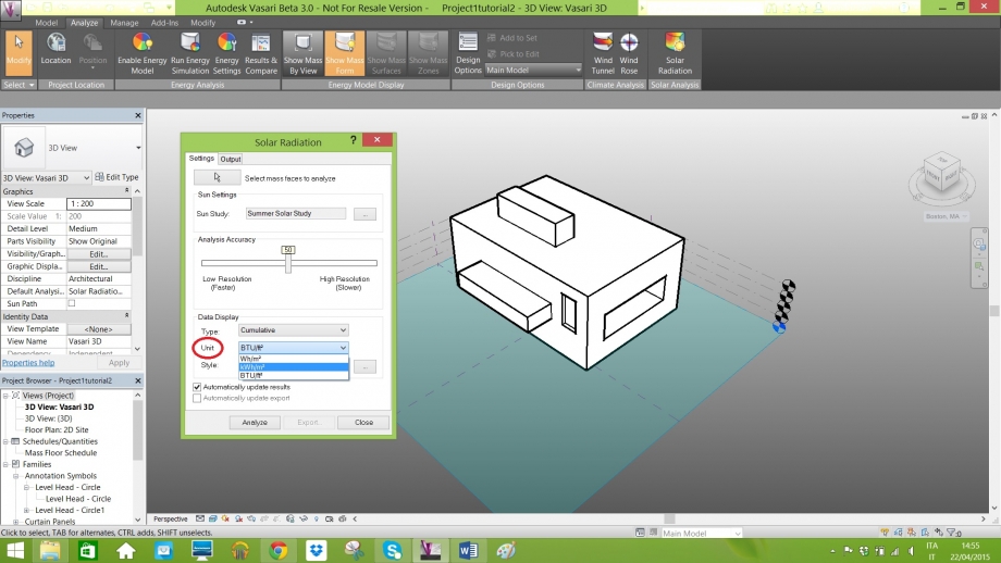
Click on Unit and change in kWh/m^2;

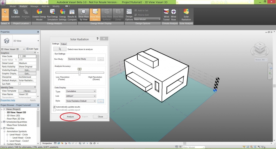
Click on Analyze to start the Solar Analysis;

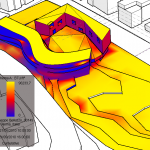
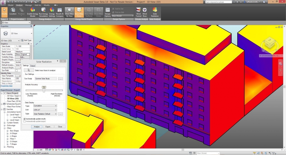
It obtains this Solar Analysis;

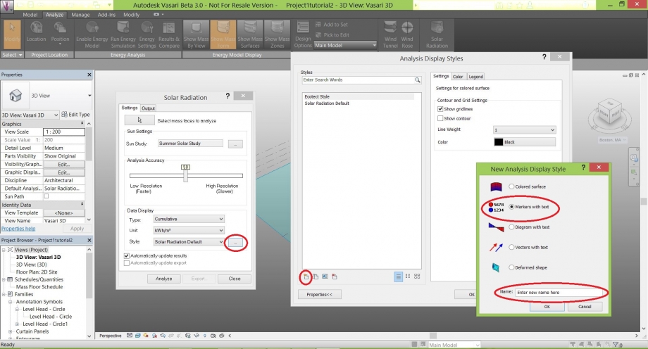
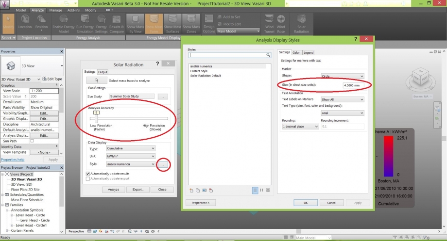
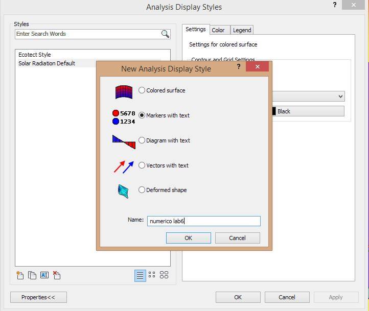
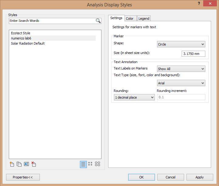
Click on ... at the Right of Solar Radiation Default;

Click on New in ordert to Creat also a numeral Analysis;

A table with a new Analysis Display will open and Select Markers with text;

Name the New Analysis and Click Ok;

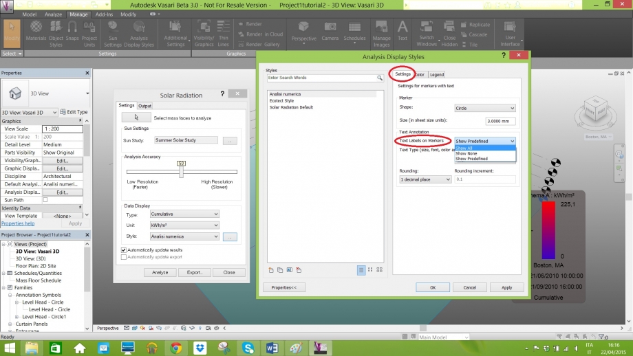
Go to Text Type and Click on Show All;

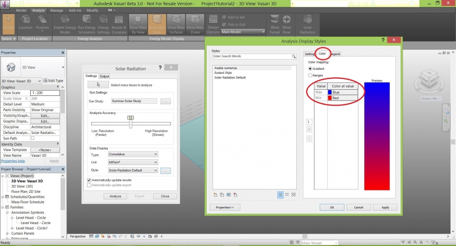
Contoll on the window of color if you are using Blue as a Max and Red as a Minimum and Click OK;

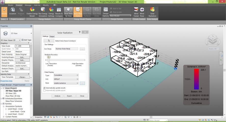
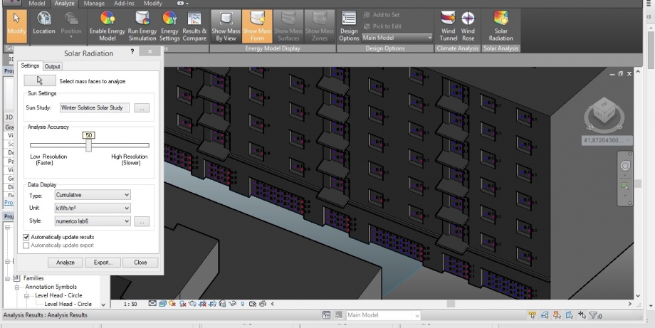
Now it obtains somethingh like that;

In order to Read better the number Change the Accuracy of the Analysis, in this case, putting 3;

This will be the result;

It has been done also the Solar Radiation in the Summer, Spring, Fall and Winter;


It has been done also the Solar Radiation with Ecotect Style in the Summer, Spring, Fall and Winter;


It has been done also the Solar Radiation with the numerical analysis in the Winter, Spring, Summer and Fall;


- 6Step Considerations
We analyzed the East front beacuse ther are balconies and we wanted to see what effects had on hand under the balconies where the basement and on the East front are the bedrooms and even if the facade is mostrly sunny in the morning only in all seasons roof absorbs heat all day and the rooms are never refreshed also there is some water infiltration on the front.
PART 2
Sun Path and Shadows Analysis of Site Project
The Area is located in Rome, exactly between Via del Porto Fluviale and Via del Commercio;

- 1Step Draw the Context and the Project
Using the same steps as the first exercise, we draw the context and the project still to be defined in the request area;

- 2Step SunPath and Shadows On
Click on SunPath and Click SunPath on;


Click on Shadows On;


- 3Step Select the different times and the different dates in order to see the Shadows
On 21 of March 2015 at 10:00 AM;


On 21 of March 2015 at 4:00 PM;


On 21 of June 2015 at 10:00 AM;


On 21 of June 2015 at 4:00 PM;


On 23 of Septmber 2015 at 10:00 AM;


On 23 of Septmber 2015 at 4:00 PM;


On 21 of Dicember 2015 at 10:00 AM;


On 21 of Dicember 2015 at 4:00 PM;


Considerations:
From these analysis we think that the project could be work.
Dom, 26/04/2015 - 13:40
 BOZZATO_ROLLI
Dom, 26/04/2015 - 01:13
BOZZATO_ROLLI
Dom, 26/04/2015 - 01:13
Scopo di questa esercitazione è analizzare la radiazione solare che subisce l’edificio da noi scelto sito in Via Vitaliano Brancati, zona E.U.R. a Roma. Per avere uno studio più dettagliato e affidabile apportiamo delle modellazioni (baconi, logge, finestre ecc.) al solido di partenza. Questo tipo di analisi aiuta il progettista a tenere conto di molti più dati per migliorare le caratteristiche dell'edificio sotto tutti i punti di vista. Arriveremo al nostro risultato finale spiegando schematicamente come impostare la nostra area di lavoro ideale per procedere all’analisi in questione e inserire le relative considerazioni.
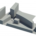
Partiamo da una situazione simile:
Cosa importante è assicurarsi che qualsiasi modellazione che andremo ad effettuare faccia parte della stessa massa iniziale e per ottenere questo risultato:
- Selezioniamo la massa cliccandoci sopra
- Selezionare “Edit In-Place”
Ogni faccia che compone la massa è intesa come piano di lavoro sul quale, una volta selezionato, andiamo a porre le nostre modifiche:
- Selezioniamo “Set”
- Selezioniamo la faccia del solido sulla quale vogliamo lavorare
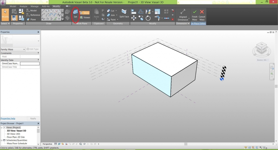
- Selezionare un opzione di disegno
- Disegnare sulla superficie selezionata la forma desiderata
- Selezionare “Create form”
- Selezionare “Solid form” (se si vuole aggiungere un corpo solido alla massa)
- Selezionare “Create form”
- Selezionare “Void form” (se si vuole creare un vuoto nella massa)
A questo punto possiamo arrivare una situazione simile:
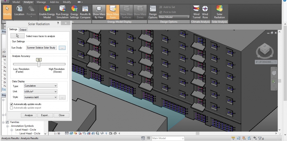
- Selezionare “Solar Radiation” nel menù “Analyze”
- Selezionare il comando “…” nella voce “Sun Settings”
- Impostare l’arco temporale che preferiamo per l’analisi
- Attivare il menù a tendina della voce “Unit”
- Selezionare l’unità di misura “KWh/m²
- Selezionare il comando “Analyze”
A questo punto dovremmo avere una situazione simile:
Possiamo ottenere due tipi di analisi della radiazione solare, quella che abbiamo appena ottenuto basata sui colori e un’altra numerica. Per ottenere quest’ultimo tipo di analisi procediamo in questo modo:
- Selezionare il comando “…” della voce “Style”
- Selezionare l’icona contrassegnata per aprire il menù “New Analysis Display Style”
- Selezionare “Markers with text”
- Inserire il nome dell’analisi alla voce “Name”
- Selezionare “OK”
A questo punto ci troveremo nella situazione in cui nel menù “Analysis Display Style” è selezionata il tipo di analisi che abbiamo appena creato, in questo caso “analisi numerica” :
- Selezioniamo la voce “Settings”
- Aprire il menù a tendina della voce “Text Labels on Markers”
- Selezionare “Show All”
- Selezioniamo la voce “Color”
- Invertire i colori dei valori “max” e “min” (facoltativo)
- Selezionare “OK”
- Selezioniamo “Analyze”
A questo punto avremo una situazione simile:
Per avere un’analisi più chiara:
- Portare il cursore dell’ “Analysis Accuracy” verso “Low Resolution”
- Selezionare il tasto “…” della voce “Style”
- Selezionare la dimensione dei caratteri nella voce “Size (in sheet size units)
Regolandosi tra questi due comandi possiamo arrivare ad avere una situazione simile a questa:
ESERCITAZIONE:
Passiamo ora all'analisi della radiazione solare mirata al nostro edificio preso in esame. Autodesk Vasari permette lo studio della radiazione solare anche su un lungo arco di tempo, opzione che permette di avere sicuramente maggiore sicurezza sulle eventuali scelte progettuali. Nel nostro caso in particolare imposteremo lo studio su l'arco di tempo di un anno ricordando di fare attenzione alla data non appena si spunta l'opzione "Sunrise to Sunset".
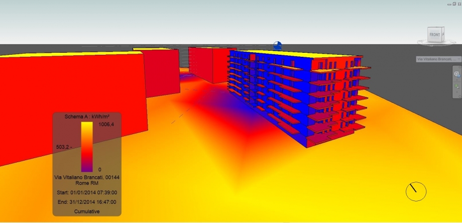
In base a quanto riportato dall'analisi della radiazione nell'arco di tempo di un anno, possiamo subito osservare come l'intera zona dove è situato l'edificio preso in esame, è soggetta a una notevole quantità di radiazione solare, questione che può essere vista da un punto di vista abbastanza negativo se consideriamo la notovele quantità di calore che può emettere il manto stradale, sotto forte irraggiamento, soprattutto nei periodi estivi. Bisogna notare anche come la più che sufficiente distanza degli altri edifici da quello preso in esame, aiuti a non causare ulteriori problemi permettendo una notevole ventilazione e una quantità di radiazione solare maggiore anche nelle zone più sacrificate.
L'involucro dell'edificio è caratterizzato principalmente da sequenze di balconi posti su ogni facciata i quali mettono in evidenza dove l'irraggiamento del sole fa il suo effetto maggiore. Per questo, tolta la facciata rivolta a Sud, il resto delle pareti dell'intero edificio risultano essere abbastanza esenti da valori alti di radiazione. Questa condizione porta a una conseguenza positiva riguardo al mantenimento di una temperatura piuttosto accettabile all'interno degli appartamenti soprattutto in estate, ma porta anche una conseguenza negativa per quanto riguarda la conservazione delle facciate. Durante le precipitazioni le facciate si bagnano e uno scarso irraggiamento permette all'acqua di intaccare le pareti lasciando aloni sulle superfici e rapidi degradi dei materiali che compongono gli infissi. Questa situazione può portare anche il rischio di formazioni di muffe anche se al momento la buona amministrazione dell'edificio scongiura sistematicamente il problema.
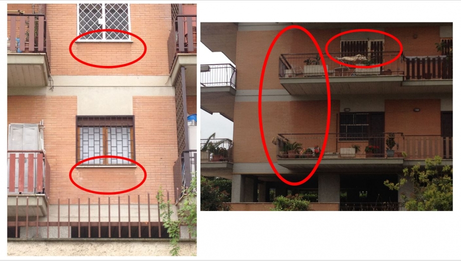
Esempi dei tipi di degrado più evidenti e presenti in tutto l'edificio. La parte di facciata compresa tra i due balconi presenta una colorazione differente dal resto e questo si nota attraverso una separazione abbastanza netta dovuta in alcuni tratti dagli aloni dati dal calcio dell'acqua piovana che contribusce a sua volta all'erosione dei vari materiali che compongono gli infissi.
Adesso andiamo a prendere in esame uno studio della radiazione solare su un arco di tempo più limitato, ad esempio il periodo estivo e quello invernale :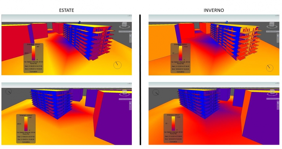 Notiamo come il comportamento dell'irraggiamento solare sulle superfici dell'edificio non cambia in maniera sensibile nonostante la diversità climatiche che comportano queste due stagioni. Possiamo affermare con certezza che i balconi sono la parte dell' edificio che più risente della radiazione solare e di conseguenza in un certo qual modo "proteggono" l'involucro da temperature elevate con eventuali conseguenze già analizzate.
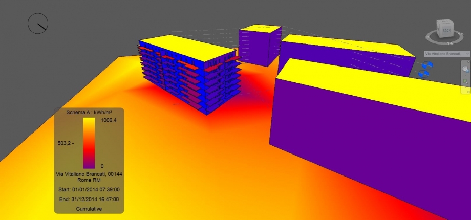
Attraverso l'analisi numerica della radiazione solare possiamo renderci conto ancora meglio del valore dell'irraggiamento che subiscono sia gli spazi intorno all'edificio che l'edificio stesso, in questo caso, nell'arco di tempo di un anno :
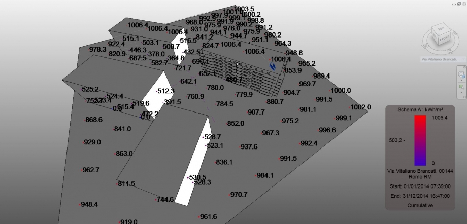
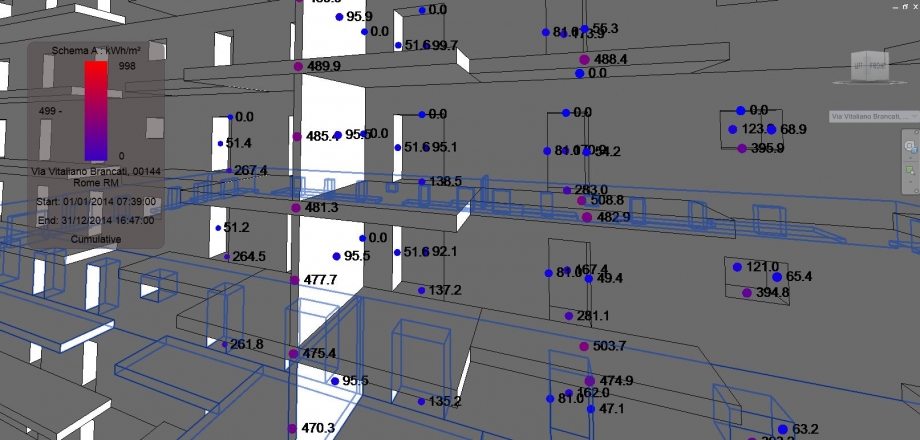
Troviamo valori piuttosto alti soprattutto sulla copertura e negli spazi circostanti l'edificio mentre i valori in dettaglio sulla facciata si abbassano notevolmente mentre quelli posti sui balconi denotano come quest'ultimi sono esposti maggiormente, confermando le impressioni avute attraverso l'analisi con i colori effettuata prima.
Abbiamo riscontrato notevoli difficoltà tecniche per poter completare la consegna analizzando il nostro progetto in via Aslago a Bolzano. Spesso quando andiamo ad aprire il file contenente la montagna, il programma ci segnala questo errore:
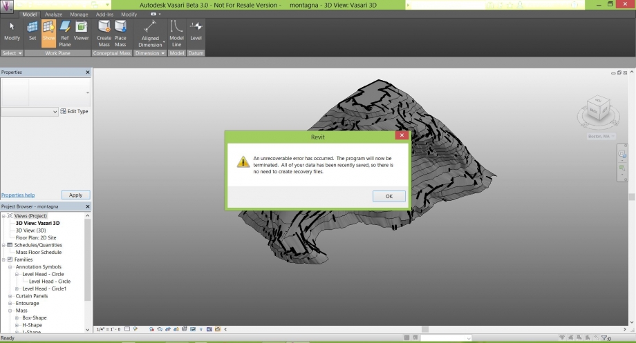
Selezionando "OK" il programma si chiude automaticamente. Le poche volte in cui si apre normalmente è comunque impossibile lavorarci.Fino all'ultimo abbiamo provato a risolvere il problema anche attraverso pc più "potenti" ma niente.
Dom, 26/04/2015 - 02:21
 Bianchi_Cinotti
Sab, 25/04/2015 - 20:30
Bianchi_Cinotti
Sab, 25/04/2015 - 20:30
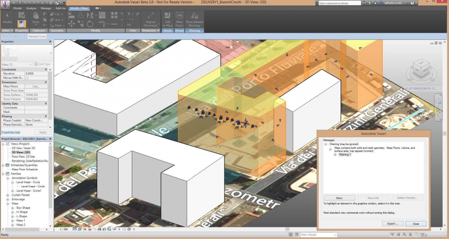
Non riusciamo ad avviare l'analisi della radiazione solare (pur avendo risolto il problema dei plug in) perchè deve esserci un problema con il solido del nostro edificio in quanto compare questa finestra (in basso a destra) se clicchiamo su Show Related Warnings!
Il fatto che non riusciamo ad avviare l'analisi dipende da questo?? Abbiamo avuto molti problemi nella creazione dei void solid delle finestre
 Farruggia_Giannini
Sab, 25/04/2015 - 15:54
Farruggia_Giannini
Sab, 25/04/2015 - 15:54
TUTORIAL
Il comando Solar Radiation è utilizzato nello studio dell'impatto termico che la radiazione solare ha sulle aree urbane e sulle opere architettoniche.
Partendo da un file nel quale già sono stati modellati degli edifici, il procedimento da seguire per ottenere l'analisi solare ha i seguenti passaggi:
1) Selezionare dal menù Analyze il comando Solar Radiation, che farà aprire una finestra di impostazioni che invierà ad altre finestre;

2) impostare la data e l'orario che si vogliono studiare;


3) impostare l'unità di misura nella quale si desidera ricevere i dati dell'analisi (kWh/mq);

4) impostare lo stile di visualizzazione dell'analisi solare da effettuare;

- Dalla finestra Analysis Display Styles si impostano tutti gli aspetti grafici con i quali saranno visualizzati i dati dell'analisi solare; a sinistra si vede l'elenco degli stili utilizzabili (Vasari ne fornisce due di default, ma è possibile crearne altri cliccando sull'icona in basso a sinistra della finestra) e a destra si vedono le caratteristiche dello stile selezionato che possono essere modificate.

4.1) selezionare tra gli stili Solar Radiation Default;
4.2) nella tendina Color selezionare Gradient come tipologia di color mapping ed impostare, dalla colonna Color at value, i colori da attribuire al valore massimo e al valore minimo che saranno visualizzati dall'analisi solare;

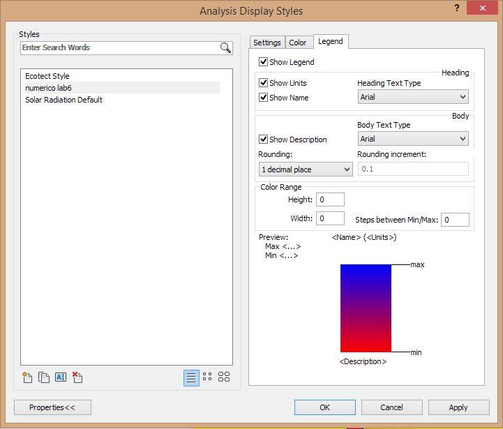
4.3) nella tendina Legend spuntare le opzioni Show Legend, Show Units, Show Name e Show Description, specificare dal menù Rounding il grado più opportuno di approssimazione dei valori di radiazione, indicare le dimensioni che dovrà avere la legenda ed infine cliccare su Apply eppoi OK (così si chiuderà la finestra Analysis Display Styles);

5) Cliccare nella finestra Solar Radiation su Analyze e in ultimo scegliere, dalla finestra che comparirà sullo schermo, se analizzare tutte le facce delle masse presenti nella vista, o procedere in una selezione di quelle che interessano maggiormente;
5.1) per far aggiornare automaticamente l'analisi effettuata nel caso in cui vengano modificate delle impostazioni, spuntare l'opzione Automatically update results;


Il risultato:

Nel caso in cui si voglia visualizzare l'analisi in forma numerica:
- ripetere i passaggi 1, 2 e 3;
nella finestra Analysis Display Style
- scegliere di creare un nuovo stile cliccando sull'icona in basso a sinistra;
- nella finestra che appare, selezionare Markers with text, rinominare lo stile e cliccare su OK;

- procedere come per i punti 4.1, 4.2 e 4.3 .

Il risultato:

ANALISI SPAZI ESTERNI_Casa in via Alipio

Nella precedente esercitazione è stato analizzato uno spazio di servizio compreso tra due edifici in via Alipio (Roma). Considerando lo studio dell'ombreggiamento, si è potuto concludere che le funzioni attribuite a questa piccola area sono adeguate al suo livello di fruibilità; restando in ombra per maggior parte della giornata, infatti, è ragionevole utilizzarla come area di passaggio più che come uno spazio di aggregazione. Con l'analisi della radiazione solare si è pressoché confermato quanto intuito dall'esercitazione precedente: lo spazio di cui si sta parlando, nei mesi invernali non è sufficientemente riscaldato dai raggi solari, per immaginare un'ipotetica ulteriore destinazione d'uso; mentre nella stagione primaverile e in quella estiva (particolarmente afose a Roma), questo stato di ombra potrebbe portare dei notevoli benefici, soprattutto nelle ore pomeridiane più calde (dalle 15.00 alle 18.00). Come si evince dai dati forniti da Vasari, il valore di radiazione massimo raggiunto il 21 dicembre è di 0.12 kWh/mq, quello del 21 giugno è invece di i 0.78 kWh/mq (in entrambi i casi ci si riferisce alle ore 12.00), ma lo spazio preso in esame non risente di tali valori allo stesso modo; infatti, a dicembre non arriva mai a ricevere il massimo della radiazione solare, come invece accade in estate nelle ore mattutine fino alle 12.00/13.00.


Per la stagione primaverile il discorso risulta essere più articolato, perché la mattina le temperature sono ancora abbastanza basse, mentre possono alzarsi anche notevolmente nelle ore pomeridiane; in più a Roma le temperature cominciano ad essere elevate già dalla fine di aprile, rendendo maggiormente necessaria la presenza di luoghi freschi. Lo spazio studiato in questa logica presenta dei vantaggi, perché risulta essere parzialmente irraggiato fino alle 12.00, per poi restare in ombra fino a fine giornata; questa caratteristica, in un mese come quello di marzo, ancora non è completamente apprezzabile, ma lo diventa pienamente con l'arrivo di maggio. Pur presentando degli aspetti positivi, l'area analizzata non sarà mai come una piazza o un giardino pubblico, dati il contesto urbano e la destinazione d'uso, ma è probabile che prevalentemente nelle stagioni calde, sia vissuta dai condomini dei due edifici come un luogo sufficientemente piacevole, per chiacchierare qualche minuto. Anche la minima presenza di vegetazione rende questo spazio più gradevole, rispetto ad un semplice parcheggio di pertinenza, ed ingentilisce l'accesso agli edifici che comunque è spesso utilizzato come un punto di incontro temporaneo.
ANALISI SUPERFICIE VETRATA
Ore 9.00 del 20/04

Come visto nella prima esercitazione, la facciata sulla quale si trova la finestra analizzata è rivolta a sud e risulta essere mediamente soleggiata in tutto l'arco dell'anno (eccetto i piani inferiori). La superficie vetrata, trovandosi al terzo piano, riceve luce diretta per la maggior parte della giornata. Secondo i valori della radiazione solare riferiti al periodo estivo, la finestra studiata è eccessivamente irradiata, quindi in una successiva modellazione è stata arretrata di 50 cm rispetto al piano della facciata; così facendo si garantisce un irraggiamento adeguato, che combina l'ombra derivata dall'arretramento e dalla sporgenza del cornicione.
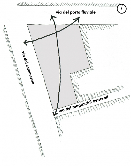
ANALISI AREA DI PROGETTO_Via del Porto Fluviale

DICEMBRE

MARZO

GIUGNO

L'area di progetto si trova in una zona con un edificato disomogeneo e in alcuni punti diradato, risultando sempre quasi totalmente soleggiata. Per questo sarà la morfologia del progetto a garantire la vivibilità dello spazio. L'intervento avrà il fine di creare spazi pubblici soleggiati il più possibile in inverno e ombreggiati in estate, sfruttando la volumetria degli edifici e soprattutto la sistemazione del verde. In base alla volumetria già progettata, la porzione più critica del lotto è quella centrale, sulla quale si è scelto di non costruire. Come si poteva immaginare, le facciate che avranno bisogno di maggior protezione sono quelle rivolte ad ovest, ma inaspettatamente si è scoperto che anche quella rivolta a nord potrebbe presentare dei problemi durante la stagione estiva, poiché il sole delle 18.00 ne illumina totalmente la superficie.
DICEMBRE

MARZO

GIUGNO

Foto dell'attuale fronte NORD da via del Porto Fluviale (11 marzo ore 17.00)

Foto dell'attuale fronte Ovest da via del Porto Fluviale (11 marzo ore 17.00)

Foto dell'attuale fronte Sud da via del Commercio (11 marzo ore 17.00)

Sab, 25/04/2015 - 19:51
 Bianchi_Cinotti
Sab, 25/04/2015 - 17:33
Bianchi_Cinotti
Sab, 25/04/2015 - 17:33
ANALISI RADIAZIONE SOLARE
a)MODELLAZIONE DELLA FACCIATA
1. Seleziona il modello >> Modify | Mass >> Edit In-Place >> Set >> seleziona il piano su cui lavorare
2. Crea la finestra in 2d >> Modify | Place Lines >> Rectangle >> disegna in facciata il 2d della finestra
3. Crea la finestra in 3d >> seleziona il rettangolo prima disegnato >> Modify | Form >> Create Form>> Void Form>> inserisci il valore di estrusione
b) ANALISI DELLA RADIAZIONE SOLARE
1. Seleziona la facciata su cui effettuare l'analisi
2. Setta il periodo di analisi : Multi-Day>> Summer Solar Study oppure Winter Solar Study >> stabilisci luogo, data e ora.
3. Adesso bisogna settare i parametri in Data Display, quindi scegli : Type >> Cumulative, Unit >>KWh/m^2, Style >> Solar Radiation Default
Analisi Invernale
La facciata su via del Gazometro da noi analizzata gode di un irraggiamento medio basso probabilmente a causa della vicinanza dell'edificio antistante che la oscura quasi totalmente. Si nota infatti come, nella parte in basso a sinistra che nella precedente esercitazione risultava quasi sempre in ombra, emerge una colorazione blu che indica appunto uno scarso irraggiamento. Inoltre notiamo come i balconi della prima colonna a destra creino un area totalmente ombreggiata e quindi scarsamente irraggiata.
Analisi Estiva
Allo stesso modo, in estate, la facciata di via del Gazometro è ancora più ombreggiata, presentando quindi un valore di irraggiamento decisamente basso.
ANALISI DELLA RADIAZIONE DELLE SUPERFICI VETRATE
Selezionare DATA DISPLAY in Styles e creare un nuovo stile in cui verrà effettuata una analisi per punti scegliendo MARKERS WITH TEXT:
Settare le impostazioni, i colori e la Legenda:

Adesso una volta creato il nuovo stile, scegliere OK e selezionare le superfici vetrate della facciata dove si vuole effettuare l'analisi:
effettuare sia l'analisi invernale che estiva selezionando il periodo come fatto in precedenza da Sun Study >> Winter solar study
WINTER SOLAR STUDY
SUMMER SOLAR STUDY
Laboratorio di Progettazione Architettonica e Urbana
Valutazione del Planovolumetrico di progetto:
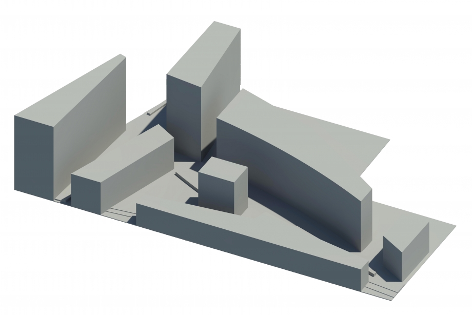
La nostra area di progetto si trova nel cuore del quartiere Ostiense, proprio tra Via del Porto Fluviale, Via del Commercio e Via dei Magazzini Generali. Il programma edilizio prevede la realizzazione di un complesso residenziale e commerciale di 7100 mq (di cui 6000 per residenze e 1100 per negozi e ateliers) rispetto ai 4730 mq di estensione dell'intero lotto. L'insediamento è avvenuto tramite due direttrici principali, la prima che da via del Porto fluviale attraversa l'area, sbucando su via del commercio, e l'altra che partendo sempre da via del Porto fluviale lo attraversa longitudinalmente fino a via dei Magazzini generali. L'obiettivo è quello di creare degli spazi aperti pubblici e privati giocando sull'ambiguita di oggetti distaccati tra loro: ne deriva un impianto planimetrico frammentato.
Nella redazione dell'impianto ci è stato di grande utilità il software Vasari, che ci ha permesso di studiare durante i vari periodi stagionali l'impatto solare sulle facciate dei nostri volumi, soprattutto in prossimità degli spazi pubblici. Avendo infatti, il nostro lotto, un orientamento longitudinale nord/sud, abbiamo cercato di insediarci garantendo alle residenze una doppia esposizione, con dei corpi ad orientamento est/ovest, in modo da garantire un buon comfort ambientale durante tutto l'arco della giornata: zona notte ad est / zona giorno ad ovest. Sul fronte nord, ovvero su via del Porto Fluviale, una strada fluida interquartiere molto trafficata e ricca di attività commerciali, abbiamo pensato a tre oggetti in linea come quinte di una piazza interna al lotto in cui concentrare la maggior parte di attività commerciali di ristoro. In questo modo l'esposizione a nord incide positivamente, poichè durante le stagioni più calde è possibile vivere i luoghi esterni evitando pensiline ed altri oggetti di ombreggiamento. Le altezze degli edifici non sono ancora quelle definitive, ma l'assetto generale dovrebbe essere il seguente: i corpi su porto fluviale più alti (altezza massima 28 m rispetto ai 30 dell'edicifio esistente più alto in prossimità dell'area), tutti gli altri di altezza inferiore ai 28m per evitare ombreggiamenti violenti degli ambienti esterni.
ANALISI SOLARE H:13,00
EQUINOZI
Come si vede, durante i periodi autunnali e primaverili l'area nord è quasi totalmente ombreggiata e quindi è possibile sviluppare all'interno della piazza che si va a creare su via del porto fluviale una serie di attività commerciali all'aperto: ristorianti, bar, bistrout con propria pertinenza esterna. Di conseguenza, le facciate degli edifici esposti a sud saranno dotati di sistemi di ombreggiamento integrati nell'involucro della facciata.

SOLSTIZIO D'ESTATE
Anche d'estate alle ore 13 l'area nord presenta un buon ombreggiamento della piazza. Negli altri spazi pubblici, sarà pensato un progetto del verde articolato poichè, come detto in precedenza in questa fascia si è data priorità all'esposizione est/ovest dei volumi.
SOLSTIZIO D'INVERNO
