 anaolmosd
Lun, 03/05/2021 - 18:34
anaolmosd
Lun, 03/05/2021 - 18:34
Per questo assamblagio ho fatto un modulo di base 1x1 e altezza variabile.
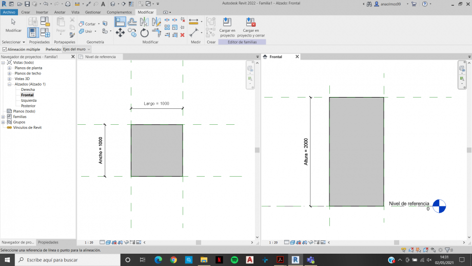
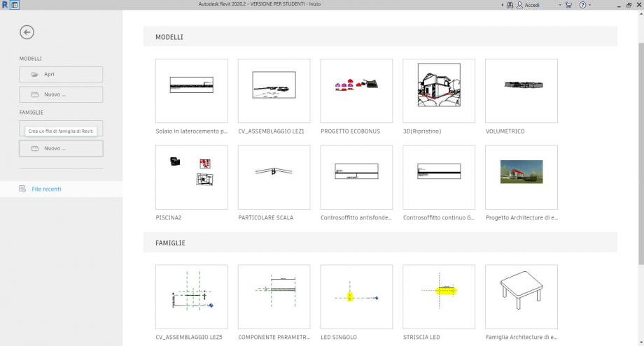
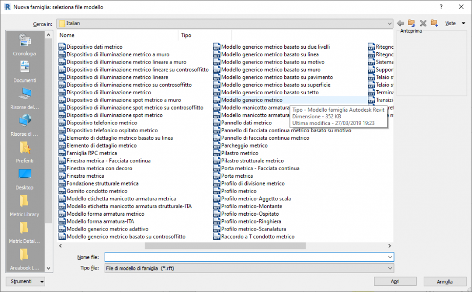
Inizio creando una nuova famiglia, selezionando "Modelo generico metrico".
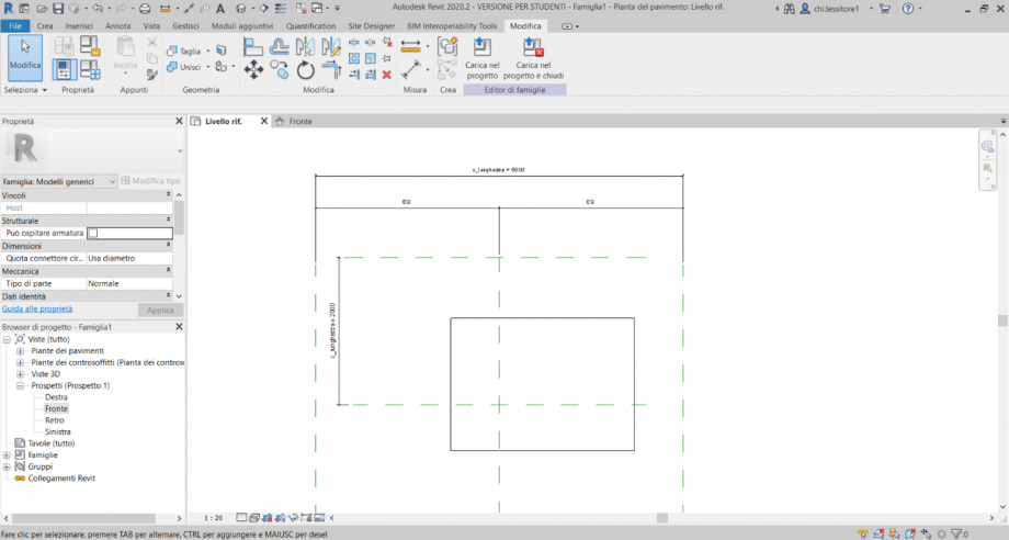
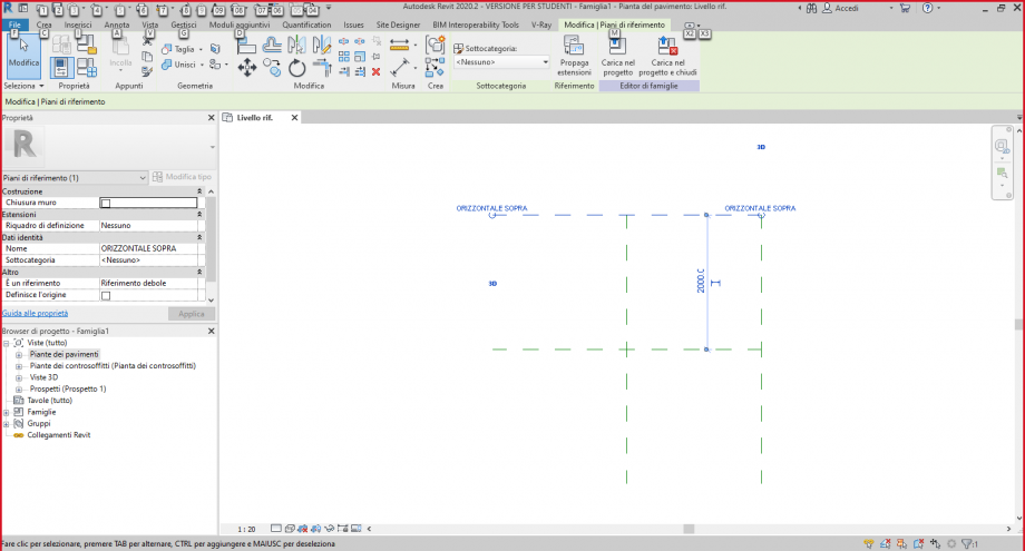
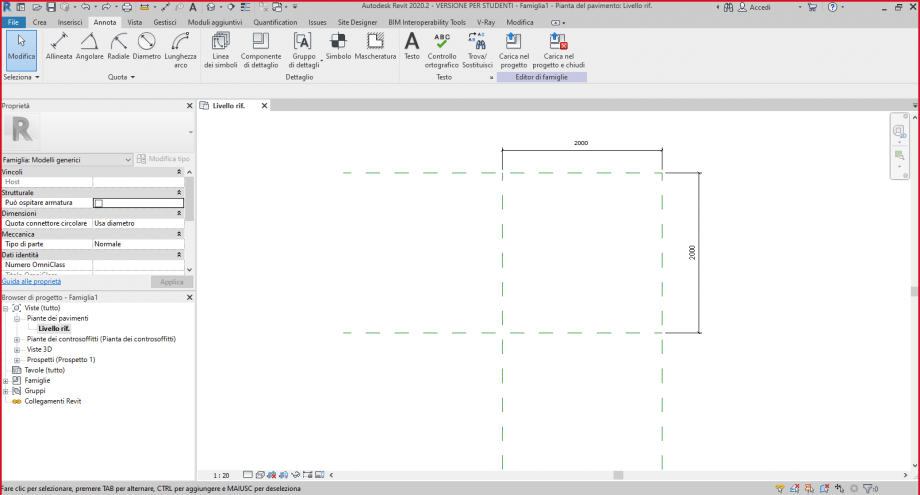
Aggiungo due piani di riferimento oltre ai due del modello e li quoto orizzontalmente e verticalmente.
Creo un rettangolo fissato agli piani de riferimento, vado alla vista frontale, creo un altro piano di riferimento e alineo e blocco il volume. Quoto la altezza.
Assegno parametri alle quote e creo vari tipi di famiglia. Salvo la familia.
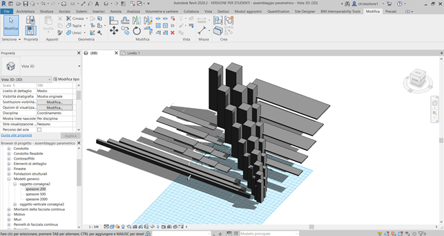
Apro un nuovo progetto. Carico la famiglia precedentemente realizzata.Creo una griglia di piani di riferimento dove staranno i oggeti.
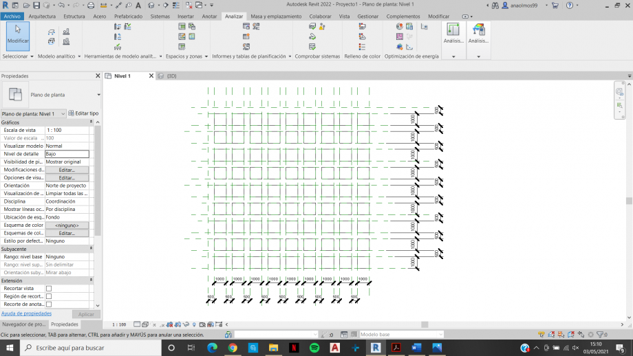
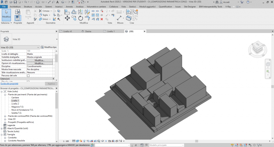
Insero i componenti parametrici da diversi tipi creando una geometria.
Creo un filtro di visualizzazione per avere un colore per ogni tipo.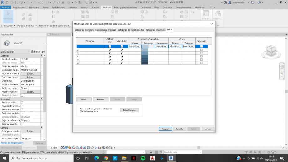
Apro la vista 3d e salvo la vista.

 Chiara Tessitore
Lun, 03/05/2021 - 16:44
Chiara Tessitore
Lun, 03/05/2021 - 16:44
Ho cominciato il mio progetto creando gli elementi della famiglia.
File >> Famiglie >> Nuovo >> Modello generico metrico.
Procedo creando dei piani di riferimento (sia in pianta che nella vista frontale), cui successivamente allineare e vincolare gli spigoli del mio oggetto.
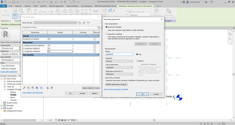
Creo i parametri da assegnare al mio oggetto.
Tipo di famiglia >> icona corrispondente a “nuovo parametro”, in basso a sinistra.
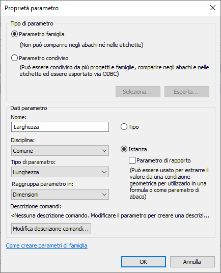
Creo i parametri condivisi “c_altezza da terra”, “c_larghezza” e “c_lunghezza” spuntando la categoria “parametro condiviso” e creando un nuovo gruppo “consegna2” in cui salvare tali parametri: questi saranno parametri d’istanza, poiché voglio che le dimensioni varino. Salvo il file .txt nella cartella relativa al corso.
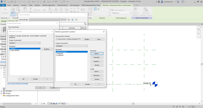
Dopo aver inserito i parametri d’istanza creo il parametro “spessore”, che decido di definire per tipo, quindi uguale per ogni elemento creato.
Ora che ho i parametri inserisco le quote.
Annota >> Allineata o (DI)
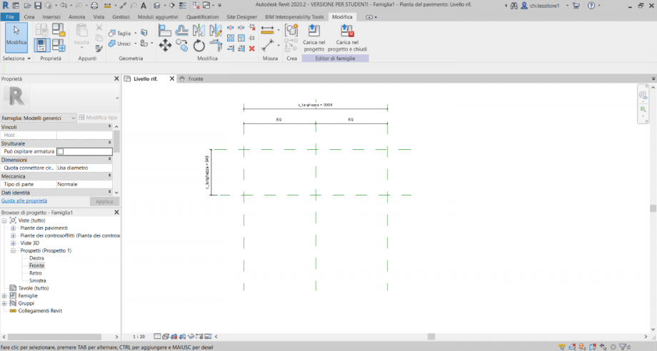
Volendo avere il punto d’inserimento dell’oggetto sull’asse di simmetria verticale, inserisco le quote in modo da rendere equidistanti i piani verticali (rispettivamente a destra e sinistra di quello preimpostato), mentre lascio che tale punto resti sull’asse orizzontale di riferimento.
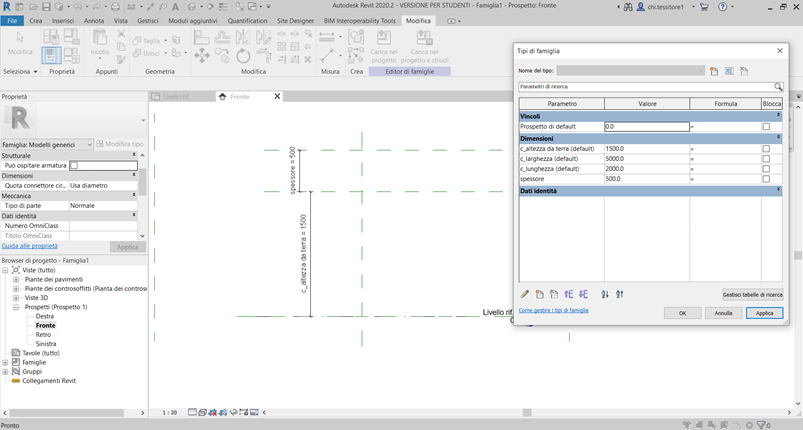
Inserisco le quote anche nella vista frontale, facendo attenzione a selezionare il piano orizzontale di riferimento e non il livello 0 (comando TAB per alternare elemento selezionato).
Associo alle quote i parametri creati: seleziono la quota >> Modifica | Quote >> Quota etichetta >> assegno l’etichetta del parametro corrispondente.
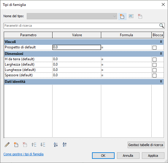
Verifico la correttezza dei parametri provando ad assegnare vari valori agli stessi dal pannello “Tipo di famiglia”.
Creo la mia estrusione: Crea >> Estrusione >> Disegna (Rettangolo) >> Modalità (green tick). Non mi preoccupo del dimensionamento né della posizione.
Modifico la visualizzazione grafica in “ombreggiato”, in basso a sinistra, in modo da distinguere più facilmente il mio elemento.
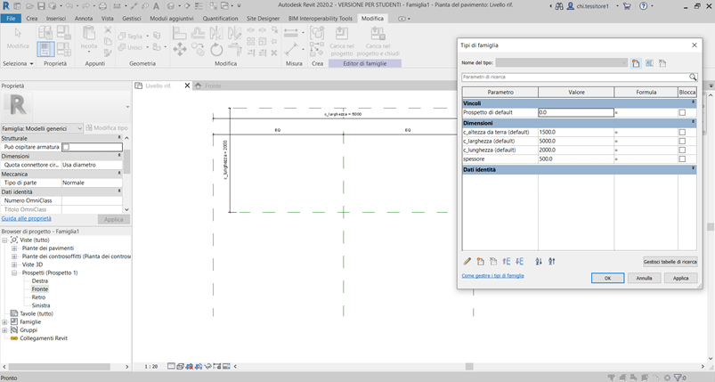
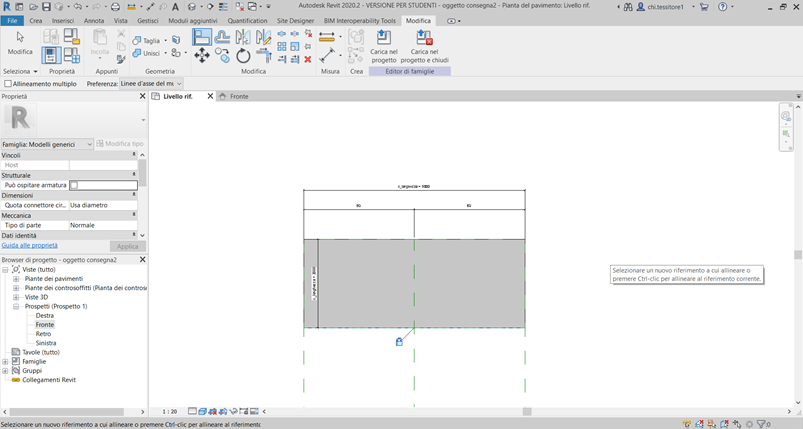
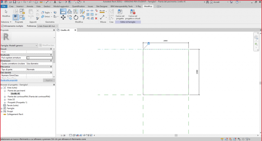
Dal pannello “Modifica” seleziono il comando Allinea per procedere ad allineare gli spigoli del mio solido agli assi corrispondenti ai piani di riferimento creati. Nel fare questo, mi assicuro di chiudere il lucchetto, facendo in modo di vincolare ogni spigolo alla corrispondente quota. Procedo sia in pianta che in vista frontale.
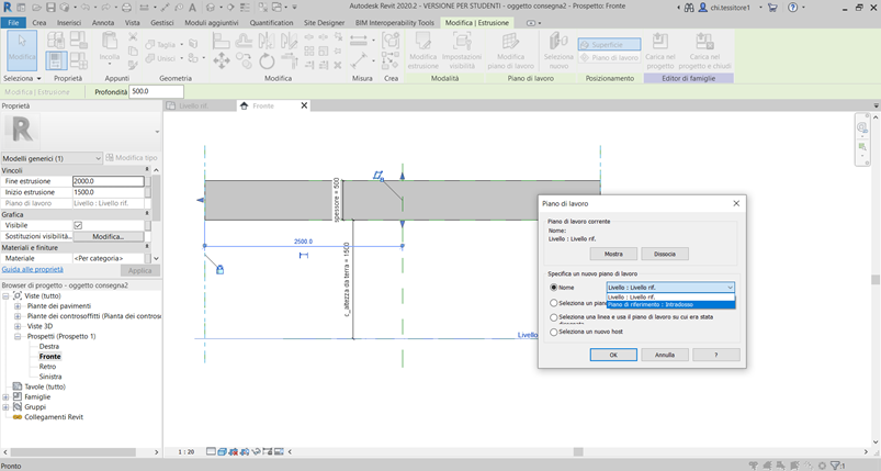
A questo punto voglio modificare il piano su cui giace il mio elemento: prima di tutto assegno un nome al piano che intendo usare, e lo chiamo “intradosso”, poi seleziono il mio oggetto e vado nel pannello “Modifica | Estrusione” >> Piano di lavoro >> Modifica piano di lavoro e seleziono il piano “intradosso” come nuovo host.
Adesso procedo con l’assegnare un rapporto di proporzionalità tra i valori corrispondenti ai parametri “c_altezza da terra” e “c_larghezza”. Inserisco “c_larghezza / 3” nella formula relativa all’altezza da terra, e verifico la correttezza della funzione inserendo alcuni valori.
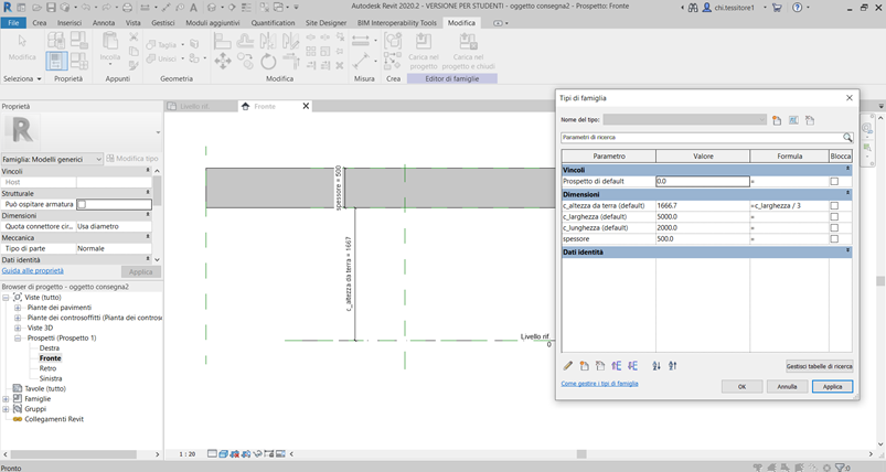
A questo punto ho terminato di definire il mio elemento base, e procedo con l’assegnare i valori relativi alle dimensioni dei parametri, ricordando che quelli condivisi non saranno vincolati dal tipo.
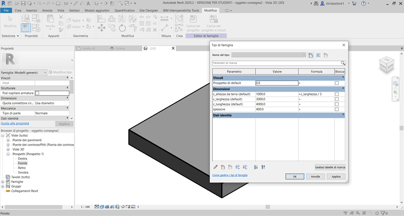
Creo altri elementi appartenenti alla stessa famiglia, che distinguo modificando la dimensione dello “spessore”.
Procedo creando un nuovo elemento: in questo caso lo chiamo “oggetto verticale” e modifico i valori e le formule dei parametri.
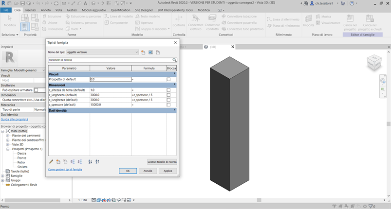
Rendo anche il parametro “spessore” un parametro condiviso e d’istanza; rendo i parametri condivisi di larghezza e lunghezza corrispondenti ad 1/5 dello spessore.
Adesso creo un nuovo modello.
File >> Nuovo >> Progetto.
Torno su una scheda appartenente ad ogni famiglia creata e vado su Modifica >> Editor di famiglie > Carica nel progetto.
Inserisco le due famiglie nel file di assemblaggio e modifico la visualizzazione in “ombreggiato”.
Inizio la mia composizione inserendo i piani di riferimento e le quote, in modo da creare uno schema da seguire nella disposizione dei miei oggetti.
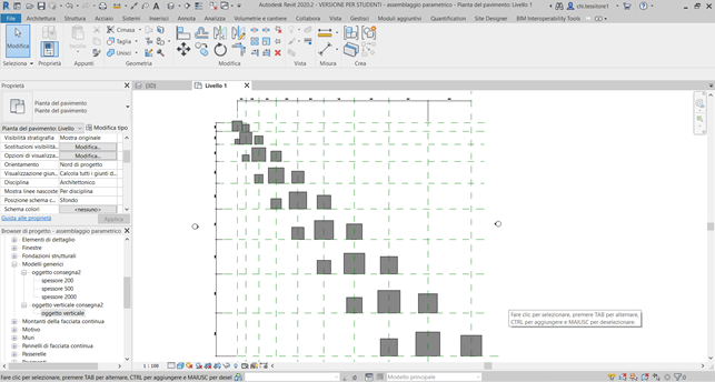
Inserisco gli oggetti appartenenti alla seconda famiglia:
Browser di progetto >> Modelli generici >> oggetto verticale consegna2 >> oggetto verticale
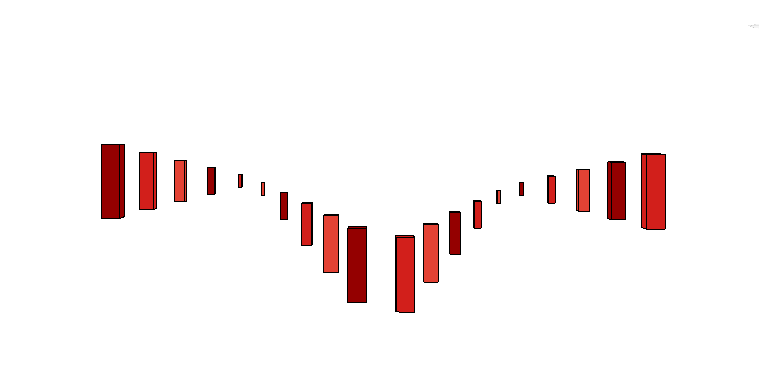
Creo una griglia di piani di riferimento in modo da incrementare le dimensioni di 1 metro verso destra e verso il basso; in corrispondenza della diagonale, costituita da quadrati, posiziono gli oggetti verticali in corrispondenza dell’asse di simmetria dell’elemento. Ne gestisco le dimensioni stabilendo una progressione regolata sull’aumento dello spessore di 2 metri (larghezza e lunghezza sono 1/5).
Utilizzo gli stessi elementi anche nelle diagonali rispettivamente a destra e a sinistra di questa centrale, iniziando con dimensioni di spessore più basse in modo da ottenere un’altezza inferiore rispetto agli elementi intermedi e da non farli intersecare tra loro.
Inserisco gli oggetti “spessore 2000” in corrispondenza di alcuni incroci sull’ultima riga e ultima colonna, dimensionandoli in modo da far corrispondere all’aumento di 5 m della lunghezza un aumento di 1 m della larghezza (e viceversa, a seconda dell’asse di appartenenza; la variazione di questi dati comporta anche la variazione dell’altezza da terra).
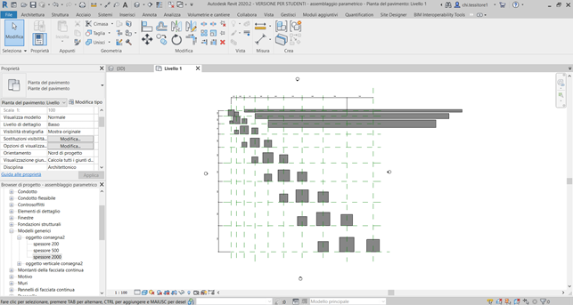
Procedo con l’allineare e vincolare gli spigoli ortogonali e riferiti verso l’interno della composizione al secondo asse verticale libero dopo quello che ospita elementi verticali. Data la natura dell’oggetto, vedo che non trasla ma si modifica nelle dimensioni.
Inserisco 3 elementi “spessore 500” in corrispondenza della diagonale ancora più esterna e ne modifico le dimensioni; man mano che mi allontano dell’angolo nord est aumento la larghezza di 5 m partendo da 20m e la lunghezza di 2m partendo da 4m. Ciò comporta un aumento di altezza da terra.
Inserisco gli elementi “spessore 200” e ne codifico la larghezza con incremento di 2 m, e la lunghezza di 4 m.
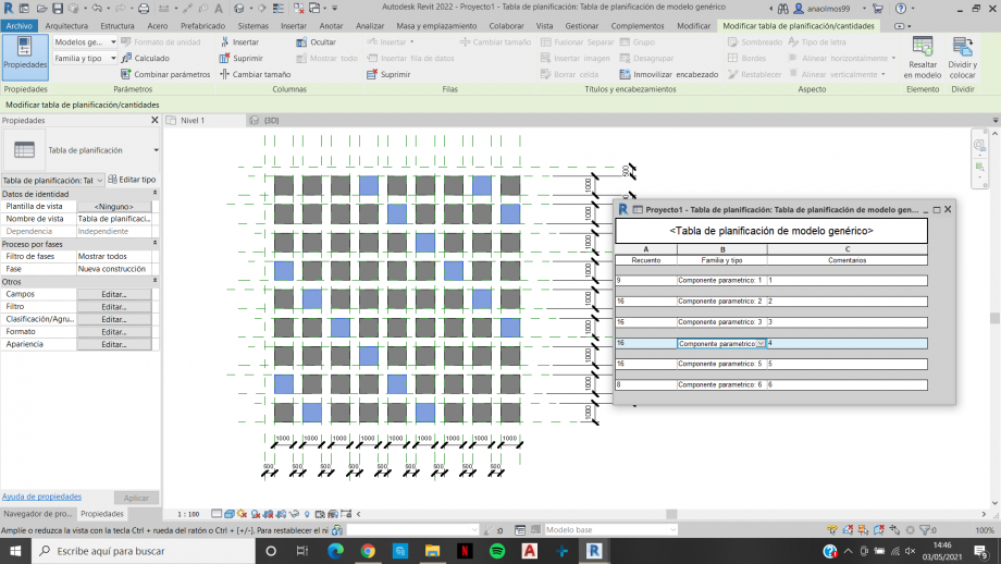
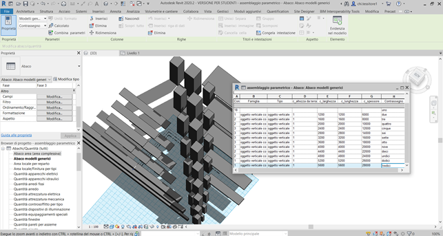
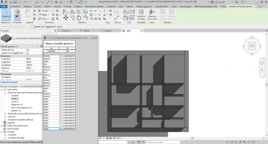
Per conoscere le quantità degli elementi inseriti apro un abaco:
Vista >> Abachi >> Abaco/Quantità >> Modelli generici
In “Campi” seleziono le voci corrispondenti ai miei parametri.
In Proprietà abaco >> Ordinamento/Raggruppamento tolgo la spunta a “Elenca ogni istanza” ed ordino in base allo spessore.
Voglio aggiungere dei “contrassegni”, in modo da poterli utilizzare per impostare dei filtri.
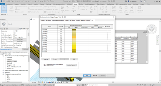
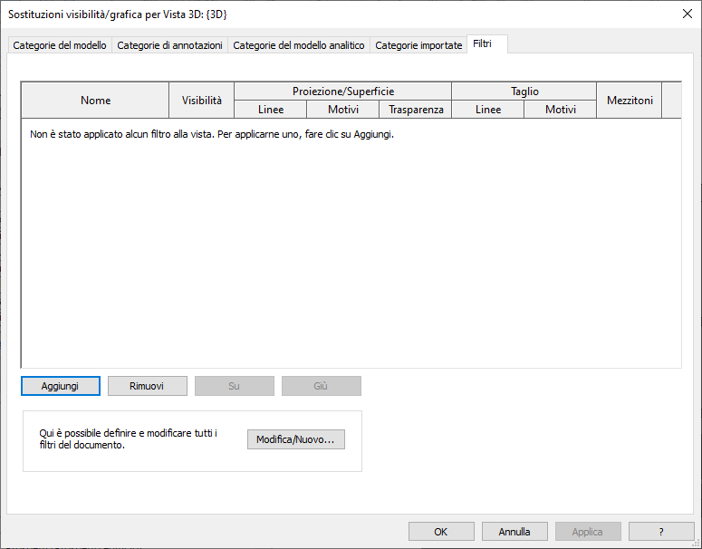
Duplico la pianta e la rinomino “colors”; seleziono la pianta e vado su Proprietà >> Grafica >> Sostituzione visibilità/Grafica
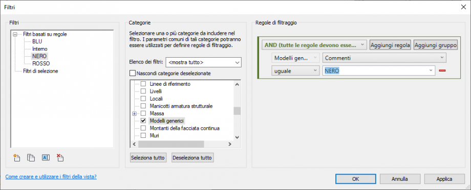
Filtri >> Aggiungi >> Filtri basati su regole >> modifica/nuovo >> nuovo filtro >> lo nomino “colore *numero del colore corrispondente al contrassegno” >> spunto i modelli geometrici >> regole di filtraggio >> contrassegno >> “uguale” >> *nome del contrassegno”. Aggiungo il filtro all’elenco e ne cambio il “motivo”.
Ripeto l’operazione fino ad assegnare un colore ad ogni contrassegno.
A questo punto il mio assemblaggio parametrico è concluso.
 Camilla d'Harmant
Lun, 03/05/2021 - 17:02
Camilla d'Harmant
Lun, 03/05/2021 - 17:02
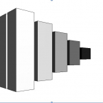
Consegna 02_Assemblaggio di variazioni
PDF in allegato
Lun, 03/05/2021 - 17:13 sofia.trimarchi
Lun, 03/05/2021 - 16:41
sofia.trimarchi
Lun, 03/05/2021 - 16:41
1 - Creo un nuovo file di famiglie, scegliendo come base “Modello Generico Metrico”.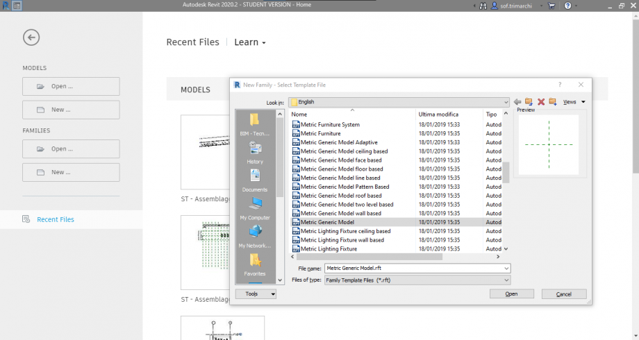
2 - Inizio a creare dei piani di riferimento digitando RP da tastiera (o da Crea>Piano di Riferimento) e li quoto tramite il comando Quota Allineata (o digitando da tastiera DI). 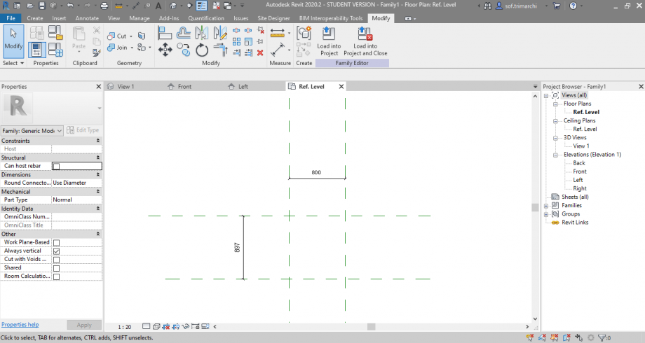
3 - Creo dei nuovi parametri da assegnare alle quote (Modifica>Tipi di Famiglie>Nuovo Parametro), denominandole “Larghezza” e “Lunghezza”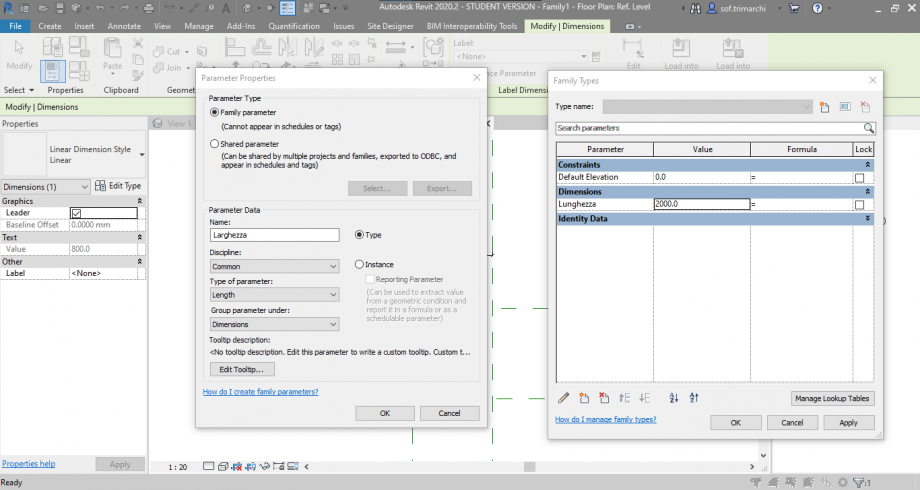
4 - Dopo aver selezionato singolarmente le quote, assegno loro i rispettivi parametri dal comando Etichetta.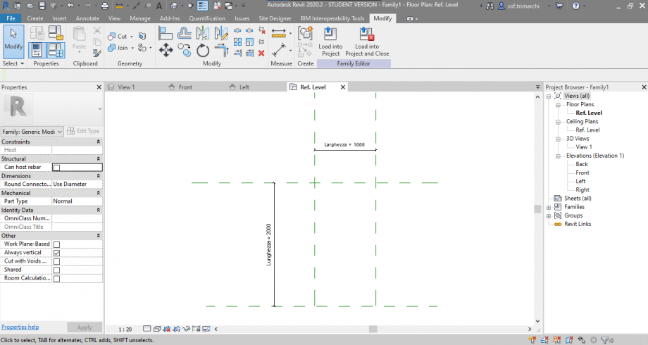
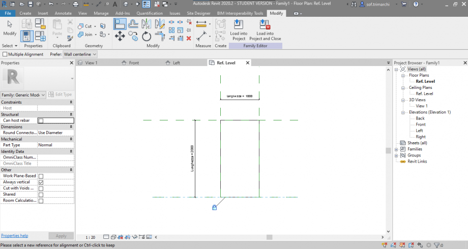
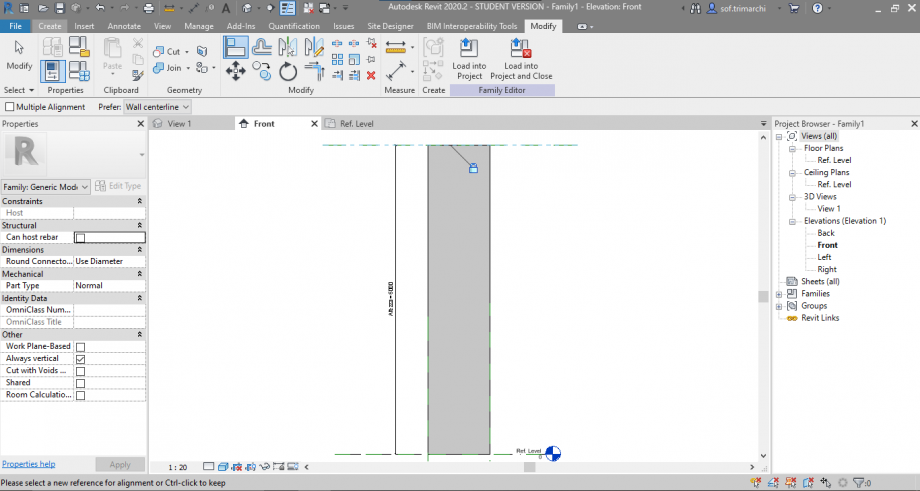
5 - Creo un’estrusione (Crea>Estrusione) che successivamente allineo e vincolo ai piani di riferimento precedentemente creati.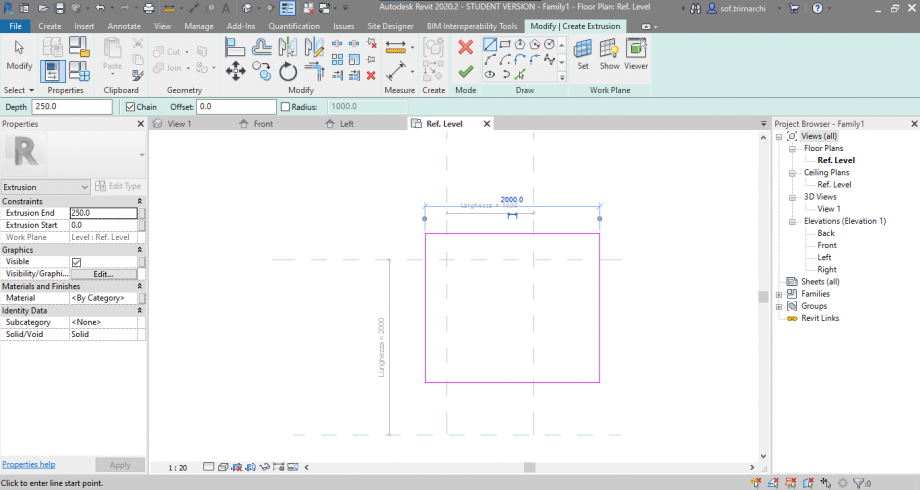
6 - Mi sposto sulla vista frontale e cambio la visualizzazione in “Ombreggiata”, dalle opzioni in basso a sinistra.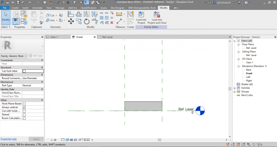
7 - Per poter definire l’altezza del solido creo un nuovo piano di riferimento; lo quoto e creo un nuovo parametro, che gli assegno. Successivamente, allineo il solido al piano e lo vincolo.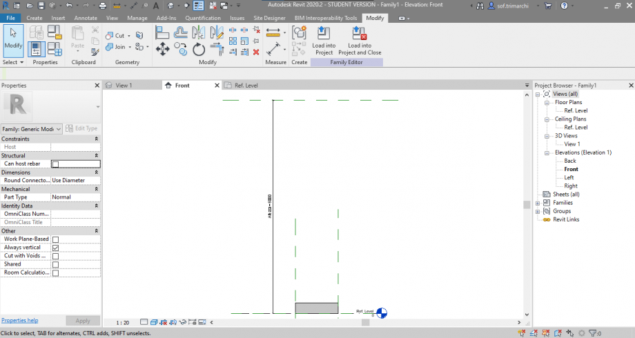
8 - In un secondo momento, modifico i parametri di “Altezza” e “Larghezza” in funzione della “Lunghezza”, assegnandogli delle formule.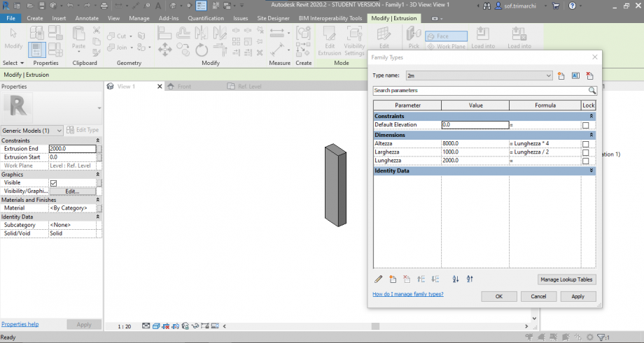
9 - Creo altre varianti della famiglia, modificando semplicemente la “Lunghezza”.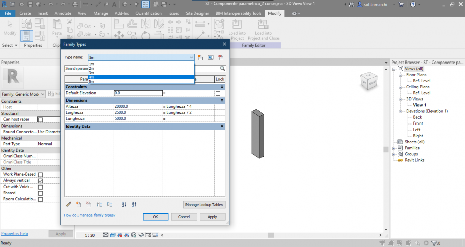
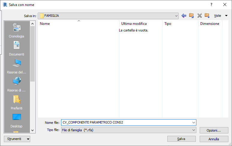
10 - Salvo la famiglia con il nome “ST-Componente parametrico_2 consegna”.
11 - Da File creo un nuovo Progetto. Subito dopo, nascondo le frecce che indicano il piano dei prospetti (tasto destro>nascondi nella vista>categoria).
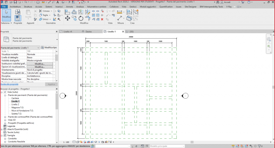
12 - Inizio col creare una serie di piani di riferimento su cui andare ad allineare il mio componente parametrico. Dopo, li quoto e scelgo di selezionare l’opzione per metterli equidistanti; inoltre, aggiungo un paio di quote ‘singole’ (tra due piani in orizzontale e tra due piani in verticale) per poter definire in un secondo momento le distanze effettive.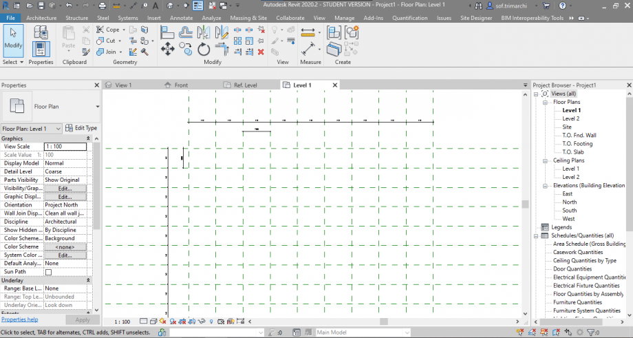
13 - Inizio, quindi, ad inserire i vari componenti parametrici all’interno della griglia precedentemente creata. Avendo necessità di allinearli secondo la semilarghezza, modifico la famiglia creando un nuovo parametro (“Semilarghezza”, che ha come formula “Larghezza” / 2) e un nuovo piano di riferimento quotato ed etichettato. Salvo la famiglia e la ricarico quindi nel file di progetto. Re-inserisco quindi i componenti parametrici nella griglia, li allineo e vincolo ai vari piani.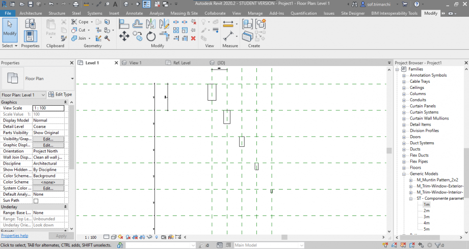
14 - Apro la vista Est e inizio a creare dei nuovi piani, in modo da potervi allineare i componenti parametrici e quindi “sfalsarli”.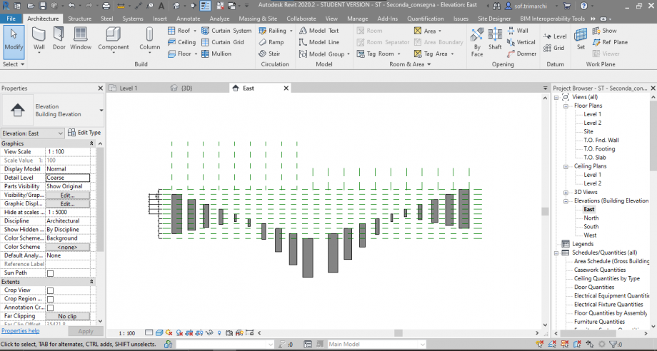
15 - Creo un abaco dove aggiungo i campi “Tipo”, “Commento” e “Conteggio”; assegno a ogni elemento un commento (A, B, C).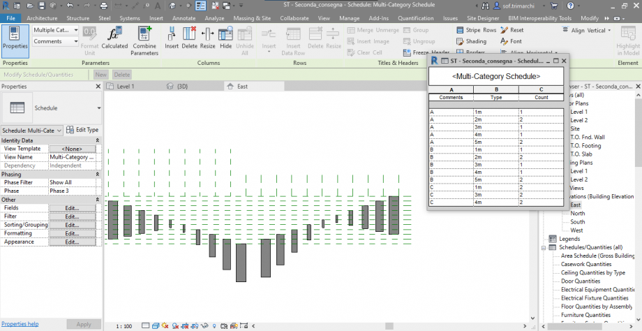
16 - Da “Visibilità/Grafica” nel pannello Proprietà creo tre nuovi filtri, uno per ogni commento. Successivamente, li carico nella scheda dei Filtri e da lì assegno un colore.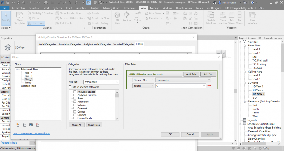
 Centonze Valerio 2
Lun, 03/05/2021 - 15:38
Centonze Valerio 2
Lun, 03/05/2021 - 15:38
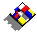
Gruppo: BACCHINI – CENTONZE_Consegna 2
Passaggio 1: Creo una nuova famiglia parametrica di Revit tramite il comando “Nuovo” e poi scelgo “Modello generico metrico”.
Passaggio 2: Disegno due nuovi piani tramite il comando “Piano di riferimento”. Un piano lo chiamo “VERTICALE DESTRA” e l’altro “ORIZZONTALE SOPRA”.
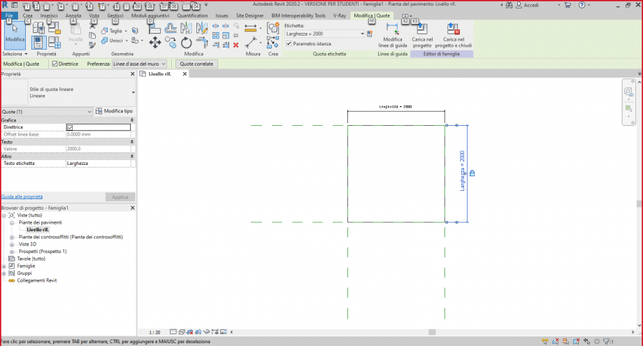
Passaggio 3: Tramite la casella “Annota” scelgo il tipo di quota e misuro la distanza dei due piani precedentemente creati rispetto a quelli originali della famiglia.
Passaggio 4: Tramite la casella “Crea” e il comando “Estrusione” realizzo un solido, e successivamente lo allineo e lo vincolo a tutti i piani di riferimento.
Passaggio 5: Tramite la casella “Tipi di famiglia” vado ad aggiungere i parametri della nuova famiglia. In particolare aggiungo 4 parametri di “Istanza” (Larghezza, Spessore, Lunghezza, H da terra).
Passaggio 6: Nella vista “Livello rif.” del “Browser di progetto” , seleziono le quote precedentemente create, e gli asssegno i parametri di istanza Lunghezza e Larghezza precedentemente creati.
Passaggio 7: Tramite il Browser di progetto, mi sposto su uno dei Prospetti, in particolare il prospetto denominato “Destra”. Mi creo un nuovo piano di riferimento chiamato “SOLE”, parallelo al Livello rif.
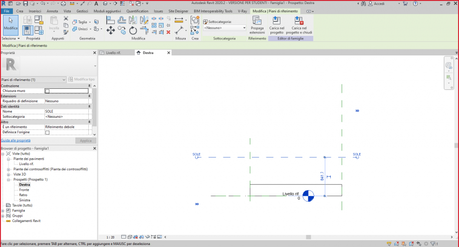
Passaggio 8: Quoto come già fatto in precedenza, il piano appena creato con il piano originale. Dopodiché, seleziono l’oggetto estruso, e gli modifico il piano di riferimento impostandolo sul piano SOLE tramite il comando “Modifica piano di lavoro”.
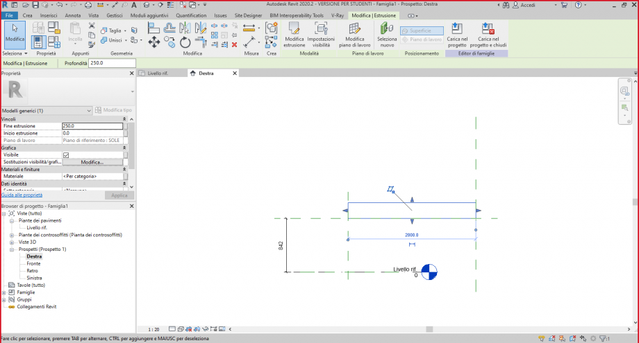
Passaggio 9: Creo un ulteriore piano parallelo al piano “SOLE”, che poi andrò a quotare rispetto allo stesso, per poi rendere la quota un parametro di istanza (Spessore), come fatto in precedenza per Larghezza e Lunghezza.
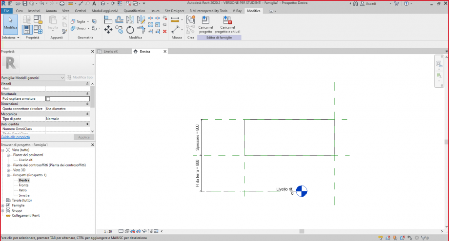
Passaggio 10: Salvo con nome la nuova famiglia in base alle convenzioni stabilite in Aula.
Passaggio 11: Aprire un nuovo progetto e successivamente caricare la famiglia appena creata, tramite la casella “Inserisci” e il comando “Carica famiglia”. Il componente parametrico si troverà tramite il browser di progetto alla voce “Famiglie” -> “Modelli generici”.
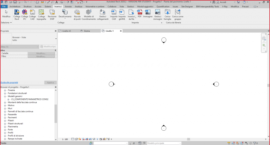
Passaggio 12: inserisco la famiglia nel progetto.
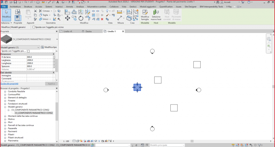
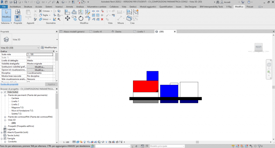
Passaggio 13: Creo una griglia di piani di riferimento, per realizzare la composizione architettonica voluta.
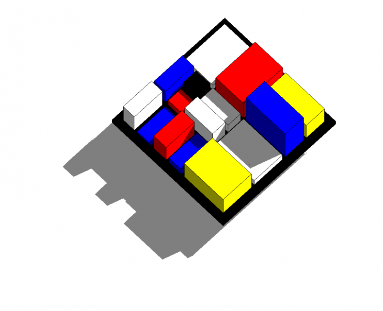
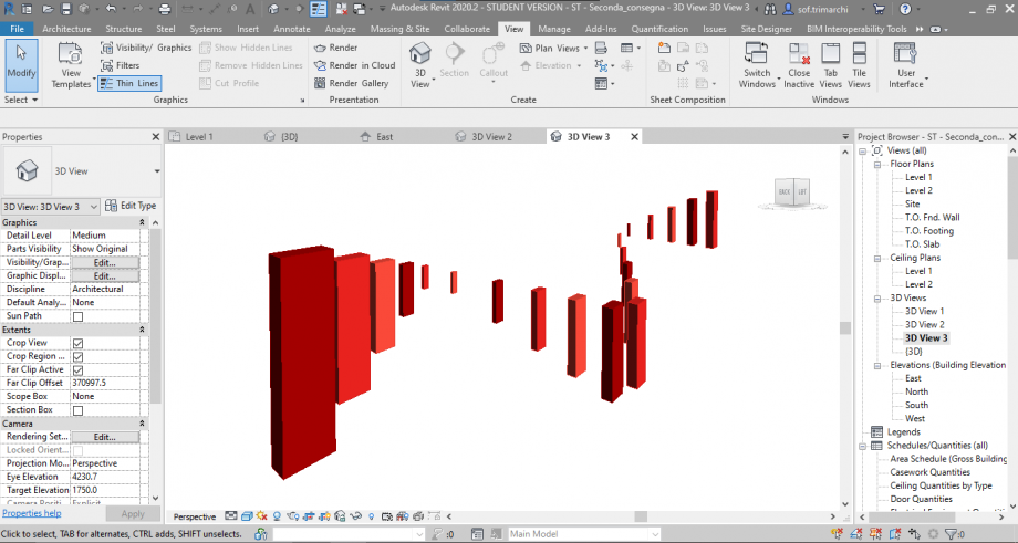
Passaggio 14: Modifico la famiglia tramite i parametri di istanza precedentemente scelti, in modo da poter variare le dimensione di uno stesso oggetto, in maniera indipendente. Inoltre cambio visualizzazione, passando dal quella piana a quella tridimensionale, impostando lo “Stile di visualizzazione” su “Colori omogenei” e inserendo le ombre tramite i due comandi nella barra inferiore dello schermo.
Passaggio 15: Vista l’idea da cui siamo partiti, il passo successivo è stato quello di rendere il tutto più vivace, attribuendo ai vari componenti un colore. Per fare ciò, ho dovuto creare un abaco dei modelli generici tramite la casella “vista” -> “Abachi”.
Passaggio 16: Per poter inserire i colori egli oggetti, devo creare Dei filtri nella vista 3D. Per fa ciò devo andare nella sezione “Sostituzione visibilità/grafica per vista 3D” -> “Filtri” -> “Modifica/Nuovo filtro” e poi impostare i nuovi filtri in base al commento precedentemente inserito nell’abaco.
Passaggio 17: Una volta creati e impostati i filtri, li aggiungo e sotto alla casella “Motivi” Assegno il colore che ho scelto.
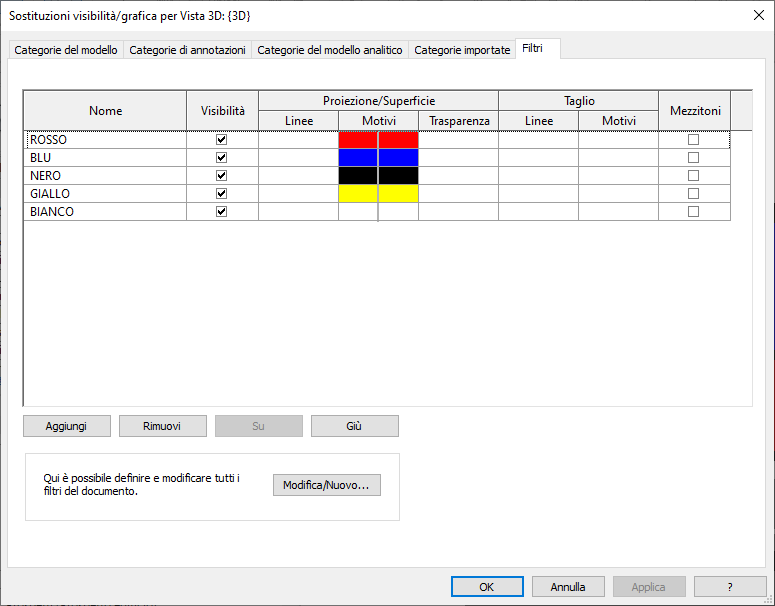
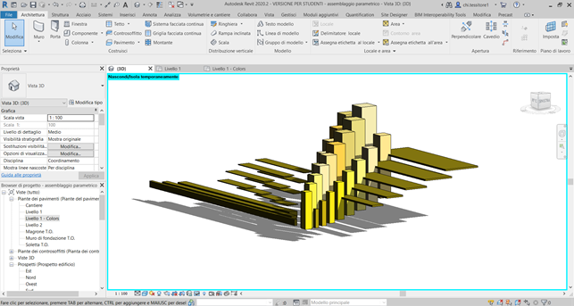
Passaggio 18: Una volta impostati i filtri, premo il pulsante “Applica” per vederli visualizzati poi nella vista.
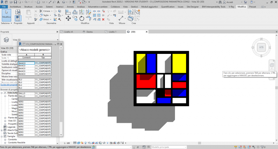
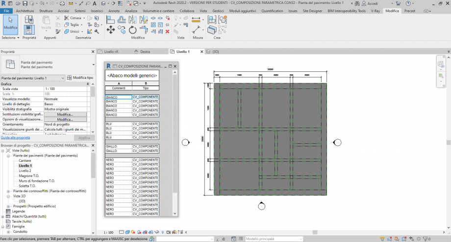
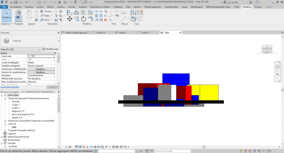
Passaggio 19: Confronto la visualizzazione 3D con la visualizzazione in pianta, e noto subito che in quest’ultima i colori non sono cambiati, proprio perché precedentemente ho modificato soltanto le impostazioni della vista tridimensionale.
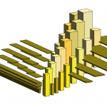
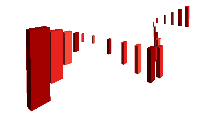
Passaggio 20: Visualizzo il progetto da varie angolazioni sempre nella vista 3D.
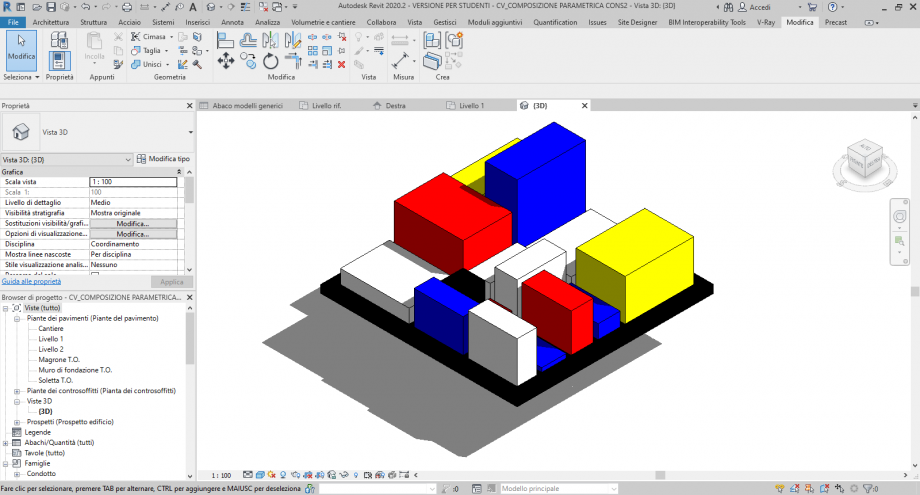
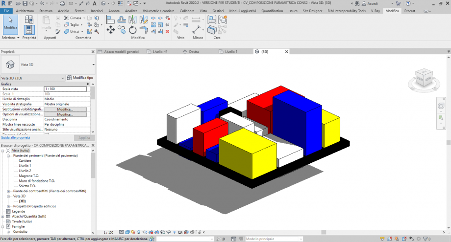
Passaggio 21: In conclusione si è scelta questa immagine poiché rappresenta al meglio ciò che si voleva esprimere. L’idea parte da una geometria bidimensionale ed arriva ad una geometria tridimensionale che non è collocabile all’interno di una precisa funzione/identità ma piuttosto che essa gli venga attribuita dai bisogni dell’osservatore.