 Nicola Moscheni
Dom, 01/03/2015 - 15:37
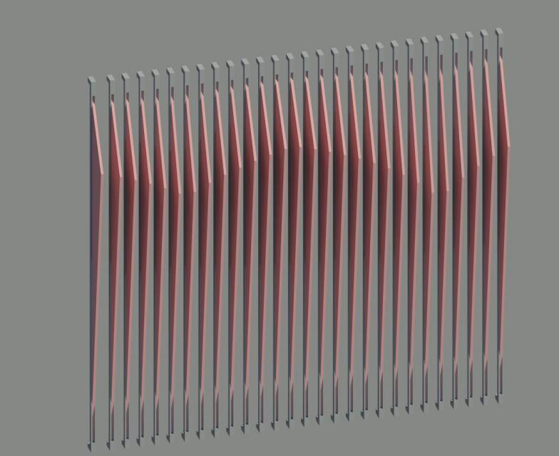
My first curtain wall is a facade with a sunshading system made by wood board (with a defined orientation).
I have to manage different parameters, in different family templates. A long process with a precise order. To explain it I will describe how to prepare curtain panel and how to "bring" the orientation parameter from the first family to the final project.
Here the two components of the sunshade: a wood board and a steel support.
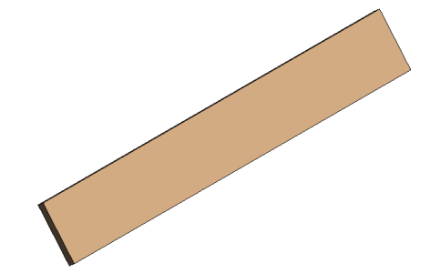
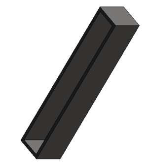
About inclination of the elements. The components' families have reference planes for the extrusion with two reference angles. They ensure to manage the inclination of the elements maintaining the mutual positioning of the planes. (Without the correspondence of the two angles the "constraints are not guaranted").
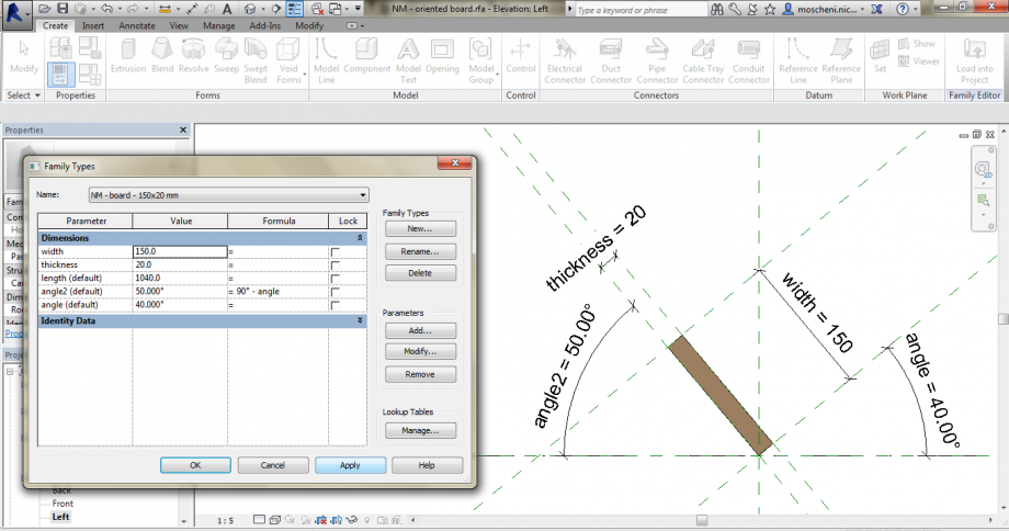
I load the families in a single "mother", the sunshade component. This family has two paramers, the length of the component (that rules also the boardlength) and the inclination of the component. The parameter "angle" of the elements (in the Properties Panel) are associated to the family parameter "inclination" . The "length" parameter of the board (in the Properties Panel) is associated to the "boardlength" parameter of the mother family (depending by the "length" family parameter).
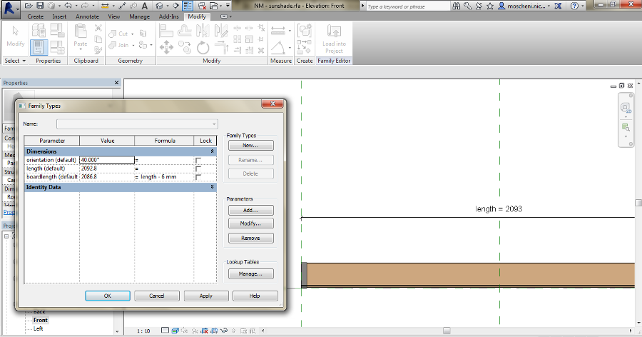
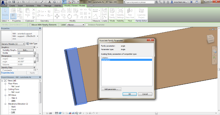
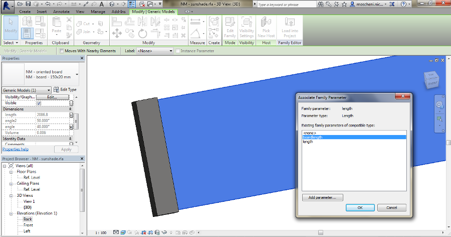
Now I load the family in a new one, where I run the array of the sunshades.
First I make the array of the element with a defined numer (with an associated "#boards" parameter).
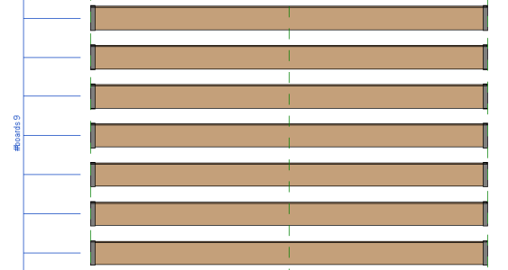
The family has also other parameters that will allow me to modify the "arraylength" and "arrayheight". Also, the "sunshadeorientation" rules the "orientation" property parameter of the single component.
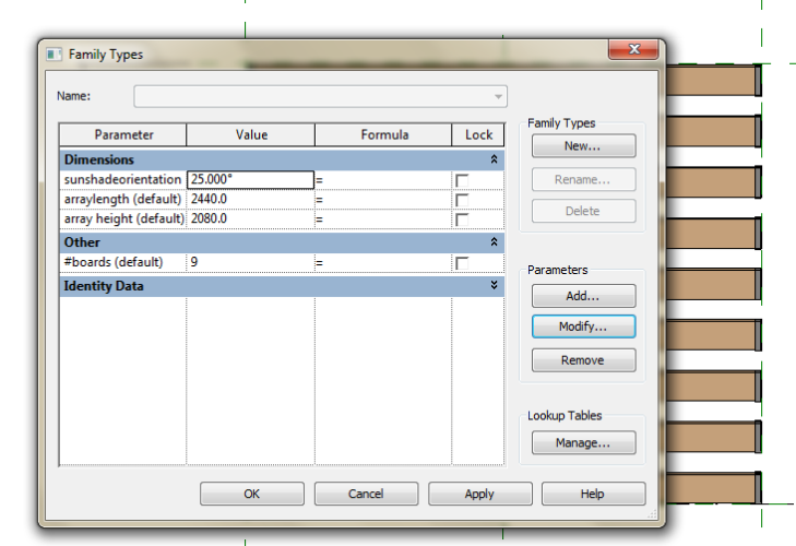
Notice: about the Alignment. For the length I aligned the signle component to the center axis (!) and matched the "sunshadelength" property parameter of the component to the "arraylength" family parameter. Then I align the array top/bottom and left/right parts to the family top/bottom and left/right axis.
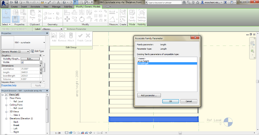
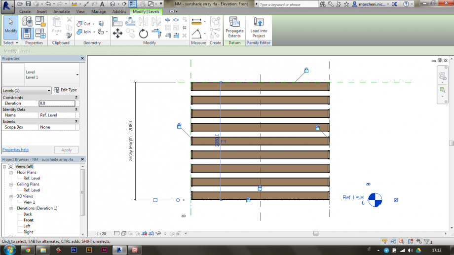
I load the array family in a Curtain Panel family and I align the array element with the main axis of the template (that have their own parameters).
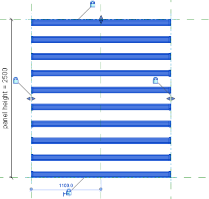
The orientation of the sunshading system (the "sunshadeorientation" property parameter) is matched with the "sunshadeangle parameter". This way, when I select the single panel in the Curtain Grid I can modify the angle in the Properties.
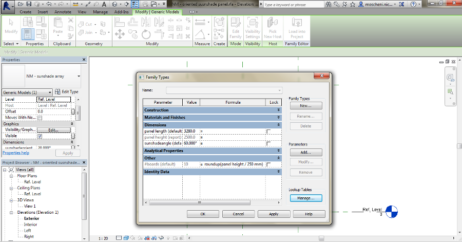
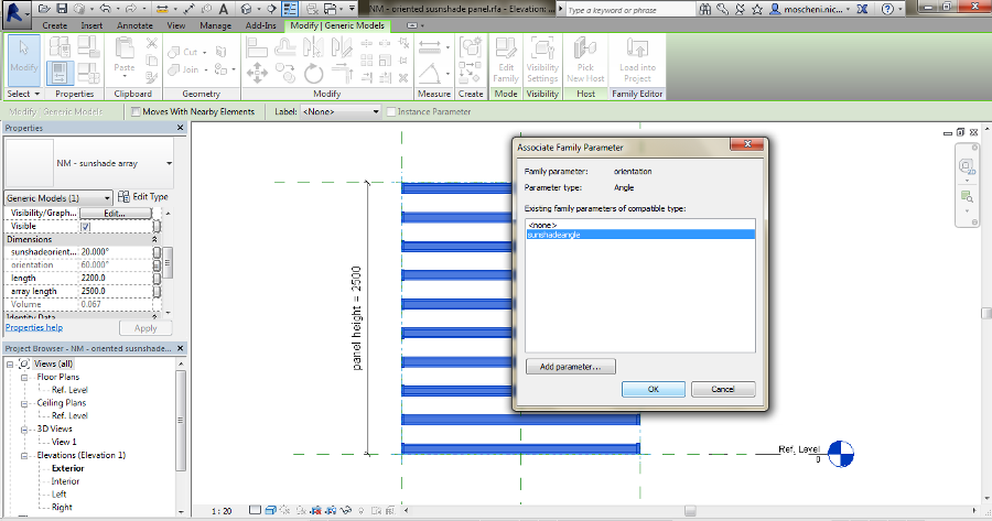
The panel is ready. (I know it seems I make a redundant step making a family only for the array but without this in the final curtain wall the dimension were not respected!)
If you want try it out check the attachement.
Dom, 01/03/2015 - 18:13
 laura.vellucci
Dom, 01/03/2015 - 15:07
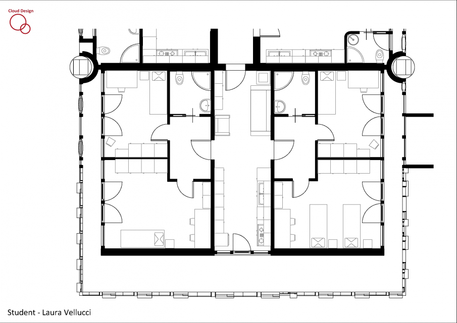
Pianta
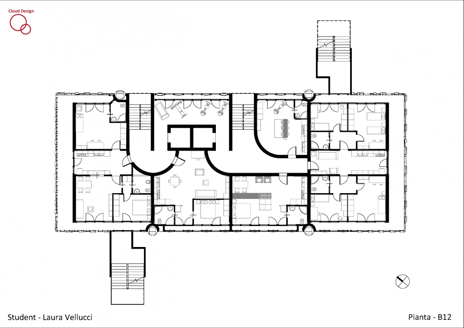
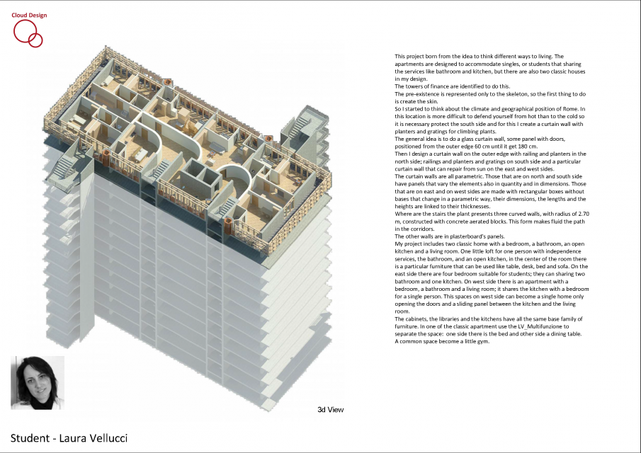
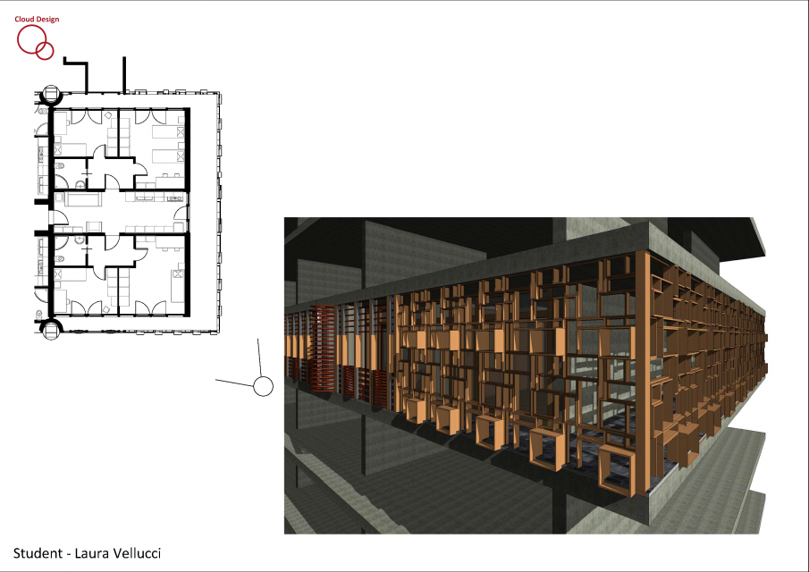
Tavola 2 con descrizione
 Tav 3 stralcio pianta in scala 1:50
 Particolare Curtain Walls
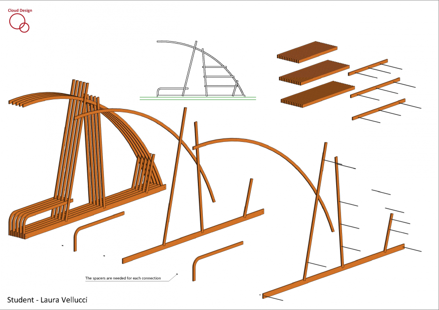
 Schedule

spaccato assonometrico
 lais efstathiadis
Sab, 28/02/2015 - 17:29
The main idea for this work was to create a Brise-Soleil made of wood segments that, by changing the angle of each one, could creat a smooth movement that reminds of a curve.
First part: create the wood segment.
Open a new family GENERIC MODEL FACE BASED and draw an extrusion on the view ELEVATION FRONT.
Add 2 parameters: LUNGHEZZA and ANGOLO. The parameter ANGOLO is the key parameter to create the movement of the Brise.
After drawing the extrusion, create different types of segments that variates on the angle:
Second part: create the aluminium structure.
Open another family GENERIC MODEL FACE BASED to create the basis structure of each segment of the brise and draw an EXTRUSION on the view ELEVATION FRONT.
Creat the parameters LUNGHEZZA, SPESSORE e BRACCIO.
Its also necessary to make a void on the extrusion that is going to be the fit for the wood segment:
Part 3: open a new mother family on GENERIC MODEL FACE BASED to join the 2 segments of the brise. In this part i joined the different angle wood segments with the aluminium structures.
With this structure you can create different shapes and draws.
 Alicia de la Torre
Sab, 28/02/2015 - 11:54
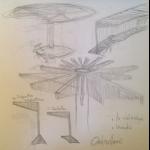
Dopo l'idea di partenza che, effettivamente era troppo modulare, ho cercato di tradurrla in chiave parametrica.
I pezzi elementari saranno assemblati (ancora devo pensare il meccanismo), una vicino all'altra seguendo una generatriz lineare o di rivoluzione.
Variazione nella longitudine dei pezzi triangolari superiori che lanciano ombra.
Variazione anche nei pezzi inferiori di supporto, in longitudine ed orientazione secondo la funzione ad albergare: supporto pubblicitario o seduta.
 Nicola Moscheni
Ven, 27/02/2015 - 05:27
Buildings (=components) = Data
In parametric desing every single element it's a data collector. I don't draw, I model. I don't simulate reality, I see it in different view.
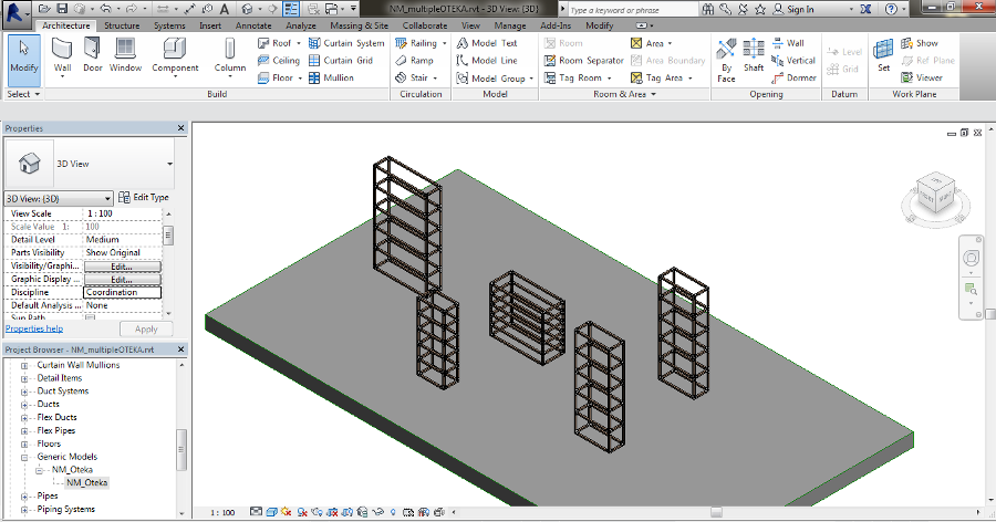
In this post I want to collect data from the OTEKA project. First of all I Load OTEKA family in a new project (with a floor, since it's a Metric model floor based, you see...reality, nothing flies). I have five OTEKA on the floor, with different dimensions (instance parameters of the family).
I need to make the order for the purchase of the furnitures and I want to do that with only one phone call to my supplier. I just need to provide him a list of components.
To prepare the list, or better the Schedule and I need Shared Parameters to do that.
In the family OTEKA I change the Family Parameters in Shared Parameters (Family Type> choose the parameter > Edit > change in Shared Parameter). I create a Shared Parameter File, a text file with all the information the project needs to share data. Inside it, there is a Parameter Group called "Dimensions" that contains "S_side1", "S_side2", "S_shelf_height" (S is for Shared). Remember to re-load the family in the project.
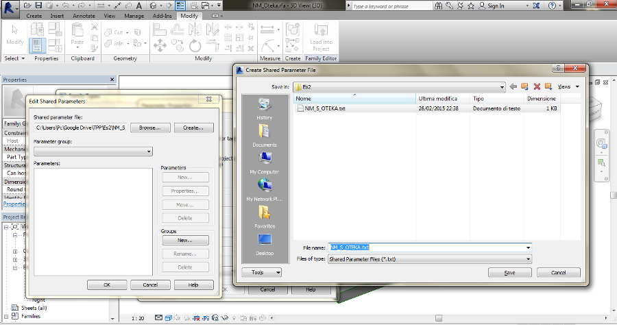
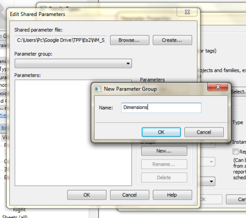
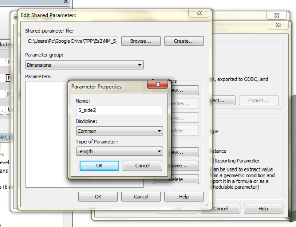
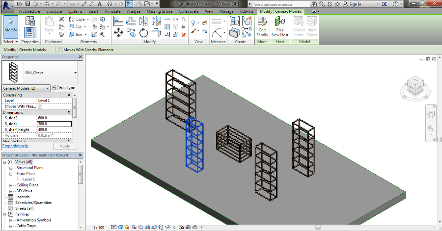
Now, it's time to share components' entity and properties.
First of all I need to check the nested families of OTEKA are "Shared". Inside the Family Category panel I flag the "Shared" cell. By this way, families and types become shared data. (check also the Family Category to make order in your project, I choose Furniture category).
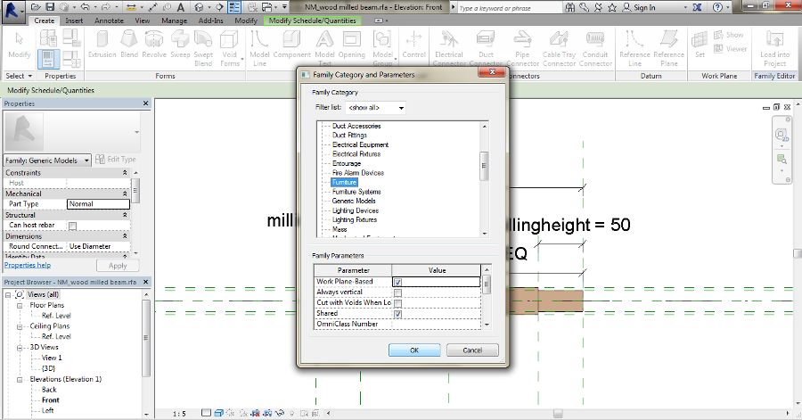
Now, I want also some parameters of the families become Shared ones. Like before I have to change the parameters, but inside my previous sharing file I add a new Group "components". The group contains the wooden beam's length for example.
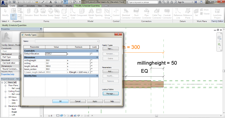
And now an example for Cost scheduling. Imagine you want to now the Total Cost of all the joints are present in the project. But joints, in this case are different types, so I need to generate a Type Parameter about cost. In the Family Types panel I add a shared (type) parameter "SjointCOST". The value changes according to every joint type. After that, I make the "Cost" parameter in "Identity Data" equal to "SjointCOST".
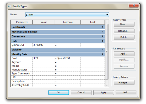
Notice: "Identity data" are type parameters so you can equal only type parameters!
Schedule creation
In "View" panel there is the Schedule tab. View, interesting. The schedule it's another way to SEE the project. Data are part of the components, sometimes an easier way to manage elements and informations that can really change the project. For example, if you modify a dimension in the schedule, it will change for "real" also in the project.
1- Choose the Category for the Schedule, the same choosen for the families.
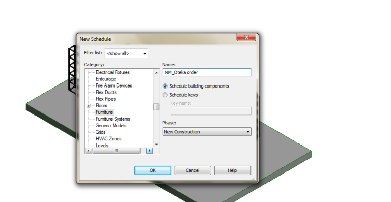
2- Select the Fields. "Family and Type" shows all the components. "Count" calculates the the quantities. "Cost" insert the price of the elements, when available in the family/material properties. You can also Add Parameters (from the shared ones).
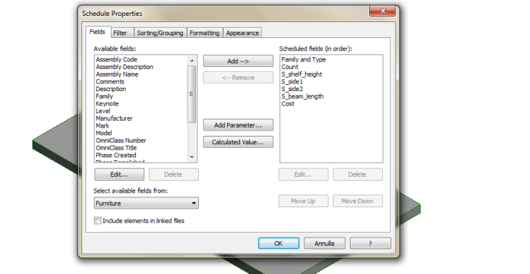
3- Insert a "Calculated Value". For example to know the Total Cost of elements. In Formula you can add a parameter.
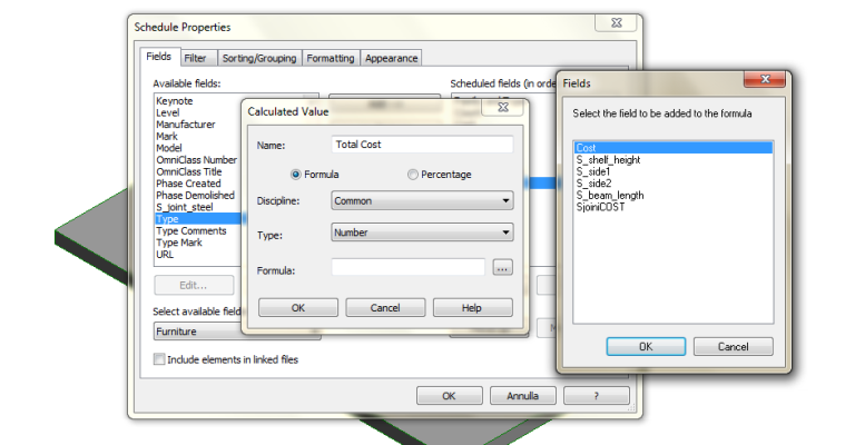
4- Sort the field to order and group them. Flag "Gran Totals" to calculate total quantities. Unflag "Itemize every instance" to group equal components.
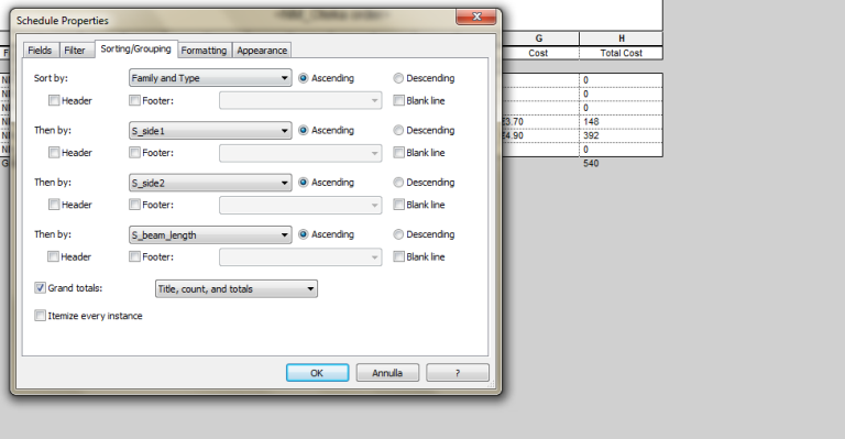
5- Format the fields to change names, to change scale units, to add symbols. For "Total Cost" flag "Calculate Totals".
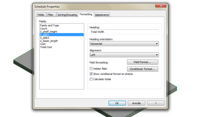
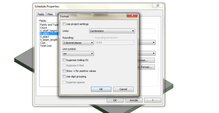
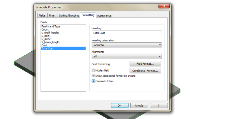
The schedule is ready.
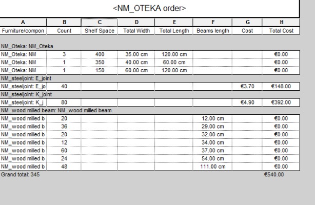
This is the easy list I can use for my phone order. If you want to do that for me, see the excel attachment exported from the schedule.
Ven, 27/02/2015 - 08:48


