


 Lodovica Silva
Gio, 29/01/2015 - 10:16
Lodovica Silva
Gio, 29/01/2015 - 10:16
Nell’ambito dell’architettura contemporanea, assistiamo “ogni giorno” alla realizzazione in forma compiuta delle più particolari fantasie architettoniche dei progettisti.
La ricerca e la sperimentazione di architetture dalle geometrie complesse è diventato al giorno d’oggi una sfida al limite dell’immaginabile.Tutto ciò è stato reso possibile, [senza sminuire la componente intuitivo-creatività del progettista] in percentuale assai rilevante, dalla comparsa dei softwares, attraverso i quali si è formalizzato il processo progettuale in algoritmi che permettono la gestione “matematica” e la generazione di forme architettoniche complesse e, perciò, variabili.
L'architettura digitale si basa su questo: usando le parole di uno dei suoi principali esponenti, Greg Lynn, essa «si serve della cibernetica per generare forme che non sono altro che calcolo» 1.
L’avvento del digitale ha influenzato radicalmente l’approccio dell’architetto verso la progettazione e il modo di concepire la forma architettonica: la ricerca di architetture dalle geometrie innovative e la consapevolezza dei nuovi strumenti a disposizione, ha reso il modello digitale una componente essenziale alla base del processo, non solo progettuale, ma anche costruttivo.
I principali protagonisti sono [oltre ai classici AutoCAD, Rhinoceros] Revit (Building Information Modeling), Catia/Digital Project e Generative Component (per progettare componenti edilizi a geometria variabile).
Questi strumenti informatici consentono «la creazione di modelli, come un insieme di parametri manipolabili» 2 , ed offrono un campo neutrale verso il quale diverse competenze convergono e attraverso il quale dialogano per la realizzazione di un obiettivo complesso.
L’uso di un’unica piattaforma per la gestione di forme e tecnologie costruttive sperimentali-innovative e sempre più articolati, risulta palesemente impossibile: bisogna ricorrere all’interazione fra i diversi software. Perciò, alla base di questa sofisticazione del processo progettuale c’è il dialogo: la collaborazione con i diversi attori del processo edilizio, estrinsecata dall’inte[g]razione dei nuovi strumenti informatici, dove ogni software, lavorando in parallelo con gli altri, «affronta diverse istanze connesse al progetto e dialoga con l’altro attraverso una serie di coordinate comuni» 3.
Questa maniera profondamente nuova di affrontare i temi della progettazione costituisce l’algoritmo alla base della nuova strategia progettuale, ed è applicabile alle diverse scale (dalla gestione di parti all’intero corpo edilizio).
L’evoluzione nel mondo dei software, specialmente dal punto di vista parametrico, ha permesso di sviluppare nuove procedure, più rapide e al contempo più precise [controllate], di definizione di tutti i componenti che collaborano alla formazione del prodotto architettonico complessivo.
Il software parametrico, infatti, permette di progettare forme di varia complessità utilizzando parametri fissi ed altri variabili secondo formule prestabilite dall'architetto. Accanto allo studio puramente qualitativo si affianca quello propriamente quantitativo, reso attraverso schedule/fogli elettronici e nesting, che descrivono la geometria del progetto evidenziando le componenti fisse e variabili, i gradi di variabilità e le relazioni tra i componenti.
In tutto ciò la figura dell’architetto viene liberata del fardello del calcolo quantitativo (anche se solo in parte; ricordo che la produttività di un software dipende dalla capacità del progettista di saperlo gestire e di fornirgli le informazioni corrette). L'architetto diviene, così, un architetto-regista, che dirigendo lo sviluppo computazionale, riesce a modificare il modello inizialmente pensato, ottimizzando la forma e cercando di limitarne i margini di errore e di imprevedibilità nella fase costruttiva.
CITAZIONI:
1 G. Lynn, How calculus is changing architecture, 2009
2 S. Converso, SHoP Works - Collaborazioni costruttive in Digitale, 2008
3 S. Converso, SHoP Works - Collaborazioni costruttive in Digitale, 2008
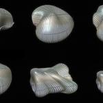
IMMAGINE:
Casa Embriologica di Greg Lynn
Gio, 29/01/2015 - 10:51 Lodovica Silva
Mer, 28/01/2015 - 21:18
Lodovica Silva
Mer, 28/01/2015 - 21:18
1_LA PIANTA (THE PLAN)
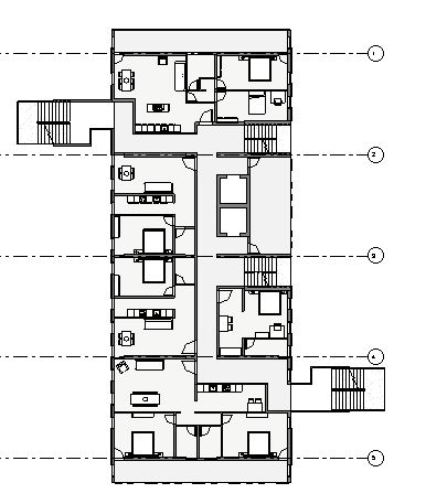
L'obiettivo di questo progetto è di realizzare quattro tipi di appartamenti a diverso taglio (dai 30 ai 92 mq).
Gli interni sono progettati in modo da dare più luce agli ambienti che ne necessitano, rilegando i servizi, ove necessario, nelle parti più interne.
Le facciate nord-sud sono parzialmente chiuse da pannelli in vetro (serigrafati?, ottimizzati?), che in parte schermino senza compromettere la vista verso il laghetto (sud) e l'eur (nord) dai balconcini.
I wanted to create four types of apartments of various sizes (from 30 to 92 square meters).
The interiors are designed to give more light to the rooms that need it the most, locating the services into the innermost parts.
The north-south facades are partially enclosed by glass panels, which partly dividing screens without compromising the view from the balconies to the lake (south) and to the eur (north).

----------------------------------------------------------------------------------------------------------------------------------------------------vista lato sud-est

----------------------------------------------------------------------------------------------------------------------------------------------------dettaglio facciata lati Nord/Sud

----------------------------------------------------------------------------------------------------------------------------------------------------dettaglio facciata lati Est/Ovest
Mer, 28/01/2015 - 21:30 Giovanna Maria M.
Mer, 28/01/2015 - 21:14
Giovanna Maria M.
Mer, 28/01/2015 - 21:14
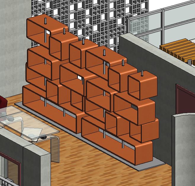
Libreria parametrica
 Mabel Sorrentino
Mer, 28/01/2015 - 17:49
Mabel Sorrentino
Mer, 28/01/2015 - 17:49
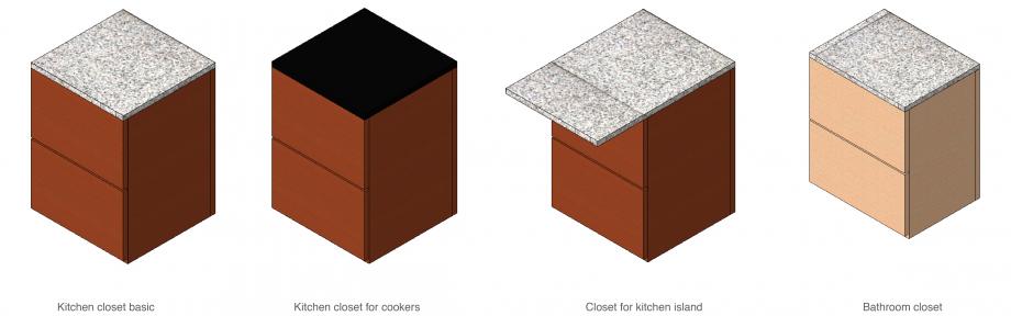
In this post I’ll explain how I shaped my closet family in order to obtain several types and use it to furnish my first flat.
I developed other similar families with the same goal in my mind.
In particular I shaped:
_a closet with drawers and I used it for the kitchen and for the bathroom
_a closet with doors and with this component I added other closets to the kitchen, I used it as a fridge, and as a wardrobe in the bedrooms.
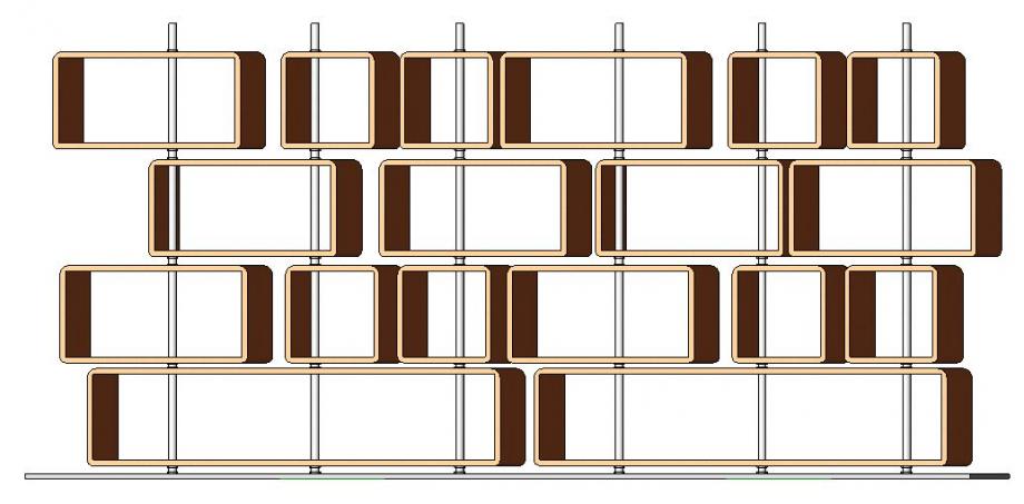
_a bookcase of which I created two different types
_a table that become a stool for the kitchen island
CLOSET WITH DRAWERS
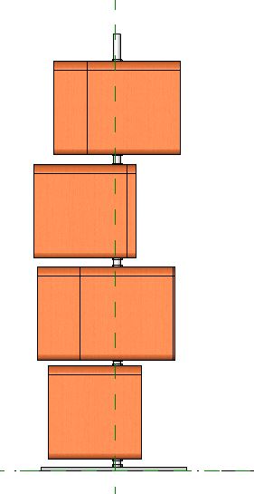
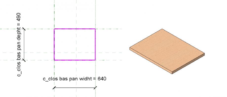
I think it could be useful show the steps for shaping just one of these families, because the others are similar, so it is important understanding the basic workflow.
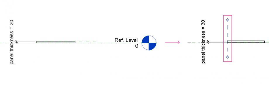
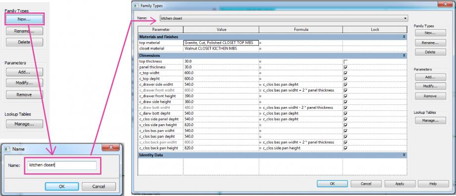
So, I started from an extrusion. I extruded the base of the closet. I assigned to the rectangle reference planes and then the parameters I needed as it is shown in the picture.
Then I needed to shape the other elements composing the closet in the same family. I mean, I previously attempt to shape the single elements of the closet in separated families and then to put them together in a new family, but in that way I wasn't able to vary the furniture as I wanted. So, after several tries I understand that the way to create a sort of series of the same basic closet was to shape all the shelves that composed the closet in the same family. To do this I discover the tool set the plane.
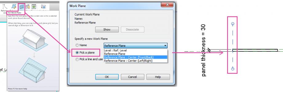 As it is shown in the picture, I drew the plane where I needed to extrude the shelf on, then I went to the create menu > set > in the drop-down menu I choose where I needed the reference plane be oriented > pick a plane > and then I click on the plane previously drawn.
Then I get the extrusion and as I done before I assigned the reference plane and the parameters.
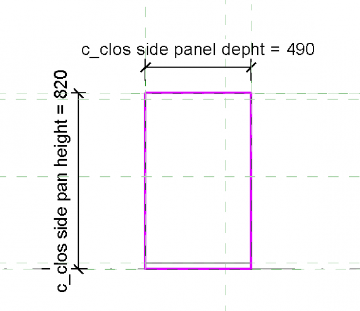
Almost all the parameters assigned were shared parameters, as I wanted to create a series.
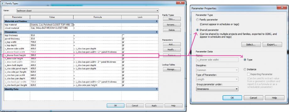 I continued in this way until I shaped all the shelves.
Then I created the types going to properties > family types > new > name of the type > and then I modified the parameters.
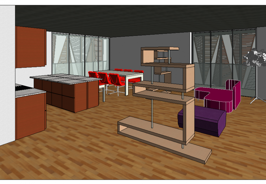
This is the results at the moment. The sofa, the lamp and the chairs are downloaded from the web.
 Mabel Sorrentino
Mar, 27/01/2015 - 21:45
Mabel Sorrentino
Mar, 27/01/2015 - 21:45
In this post I explain how I created personalised curtain walls and architectural walls for my project.
Before starting to show my workflow I want to list which were the elements I introduced to complete the flat.
Curtain walls:
- glazed parapet
- glazed window
- structural wood wall 23 cm
Basic walls:
4. inner wall 13 cm
5. exterior shelf 7 cm
6. interior shelf 3 cm
7. plaster 1.5 cm
So the base to obtain the curtain walls of the first group was the basic curtain wall, in the second group I created the different types of wall starting from a basic wall and then I personalised the layers.
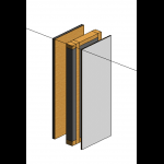
STRUCTURAL WOOD WALL 23 CM
In the project browser go to Curtain walls mullion > rectangular mullion > duplicate > rename. In this way I created a personal wood mullion in order to use it as mullion for the structural wood wall. I assigned to this mullion the material I wanted (GLULAM 28C).

Then I duplicated and renamed a basic curtain wall. Architecture tab > wall > architecture wall > curtain wall. In the curtain panel menu I assigned the insulation panel previously created and I assigned my personal wood mullion for the grid.


With a similar workflow I created the glazed curtain walls for windows and parapet.


INNER WALL 13 CM
I started from a basic wall. Architecture tab > wall > architecture wall > basic wall > duplicate and rename. Then I change the structure layers in order to obtain what I needed.

(This symbol visible in plan view is useful to swap the exterior with the interior side of the wall)


In the same way I shaped the exterior and the interior shelf to complete the structural wood wall.

And at last the plaster useful with the concrete existing structure.
P.S. I don’t know how to attach the curtain wall. Are they already visible in my project loaded on glue?
Mar, 27/01/2015 - 22:07