


 Stefano Stoica
Sab, 15/12/2018 - 13:36
Stefano Stoica
Sab, 15/12/2018 - 13:36
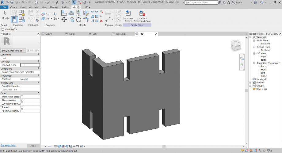
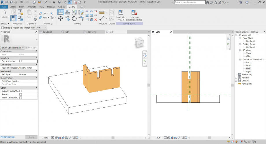
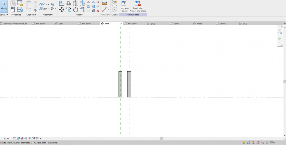
-Per laseconda consegna sono partito creando una nuova famiglia (Generic Metric Model- Line Based), nella qule ho creato una "PARTE":
-Successivamente ho creato altre due famiglie, una "face based" e un'altra "line based". Nela "face based" ho caricato la prima "PARTE" affinche la parte larga appoggiasse sulla faccia di riferimento. Anche nella seconda famiglia "line based" ho caricato la "PARTE" costruendo due aste parallele nella quale ho specificato che il parametro che descrive la distanza tra le due parti fosse lo spessore dell'asta "facebased".
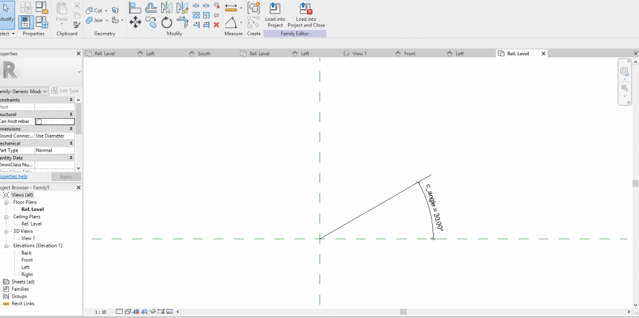
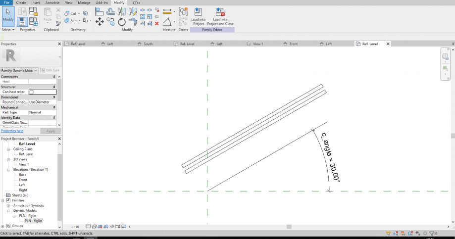
-Poi ho creato una 4°famiglia, questa volte "generica" dove ho montato insieme le due famiglie precedenti dove l'unico parametro impostato fosse l'angolo tra i due.
-Questa Famiglia è la mia "famiglia madre" che ho caricato in un file di "montaggio"
-Qui successivamente ho variato il parametro (angolo tra le due "parti figlio") per ottenere l'assemblaggio definitivo.
 Patrizio Lollob...
Ven, 14/12/2018 - 15:58
Patrizio Lollob...
Ven, 14/12/2018 - 15:58
La seguente è un'esercitazione di assemblaggio tettonico, con parti semplici montate e composte tra loro.
Il primo è passaggio consiste nel costruire la famiglia madre.
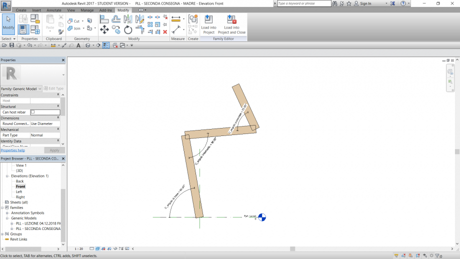
Famiglia MADRE
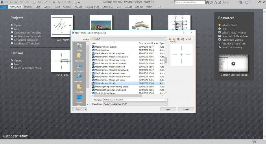
Apro family - new - metric generic model
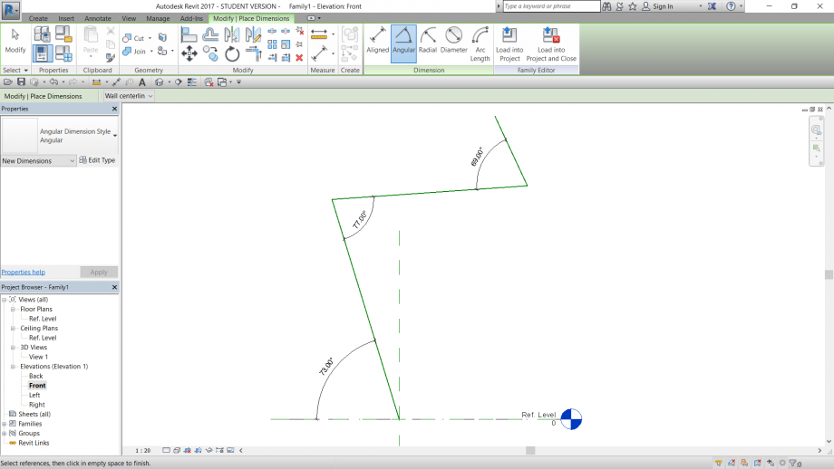
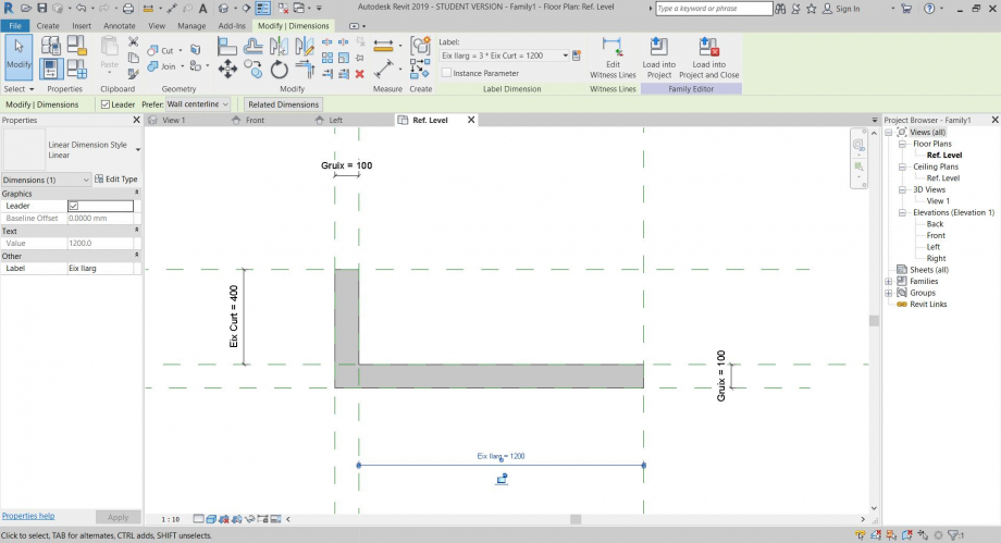
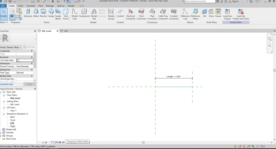
Mi posiziono nella front view e costruisco secondo progetto le reference line, ovvero linee di riferimento utili alla composizione.
Inserisco le annotazioni angolari e le associo a parametri angolari di istanza e condivisi.
N.B. Bisgogna verificare sempre i vincoli. Per garantire che le linee di riferimento ruotino in relazione l'una alle altre è necessario utilizzare il comando Set - Pick a plane - cliccare sulla ref. line che sarà da base per l'inserimento delle successive.
Famiglia FIGLIO 1
Il seguente passaggio serve a costruire una parte che andrà poi caricata nella file madre:
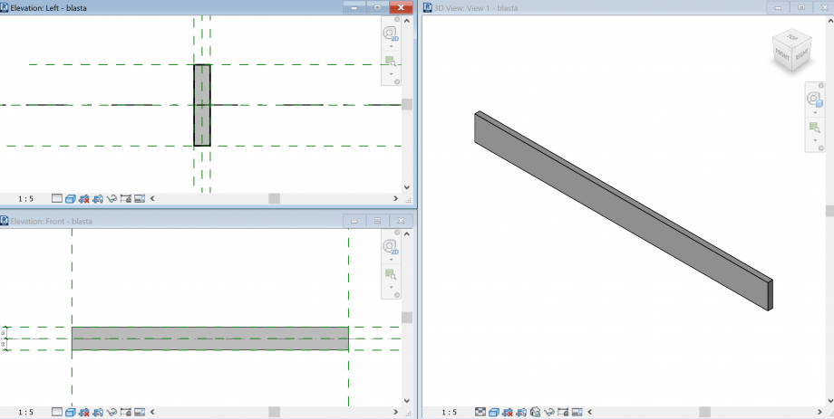
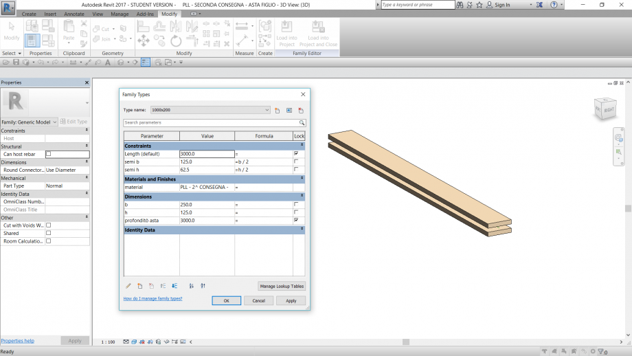
Apro family - metric generic model line based.
Uso un modello line based perchè è utile per la costruzione di un elemento simmetrico associato a un asse di riferimento.
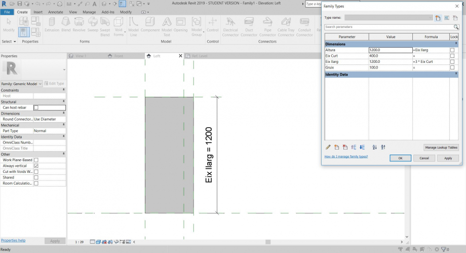
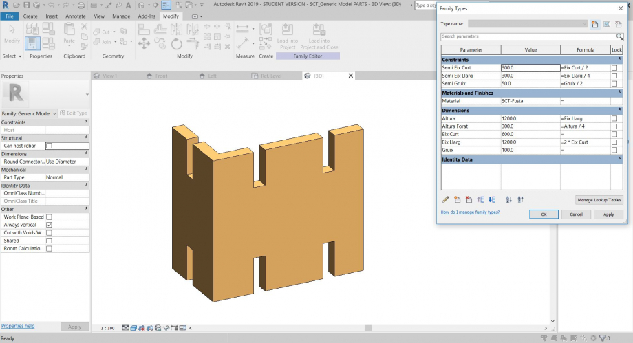
Con i reference plane e l'estrusione genero una coppia di aste parametriche simmetriche. Tra i vari parametri (visibili in foto) associo alla parte anche il materiale, nel mio caso legno.
Famiglia FIGLIO 2
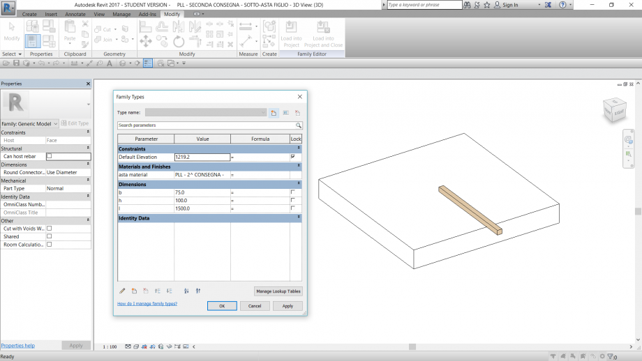
Anche in questo caso genero una parte da caricare nel file madre, più precisamente da posizionare sopra l'oggetto figlio creato in precedenza. Per questo motivo procedo come segue:
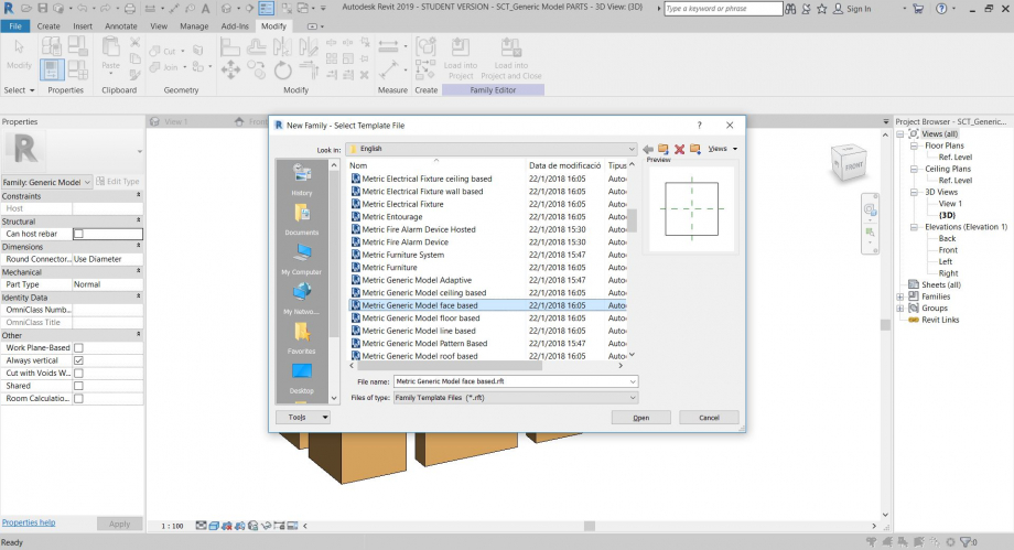
Apro family - metric generic model face based.
L'oggetto è parametrizzato e ad esso ho associato un materiale.
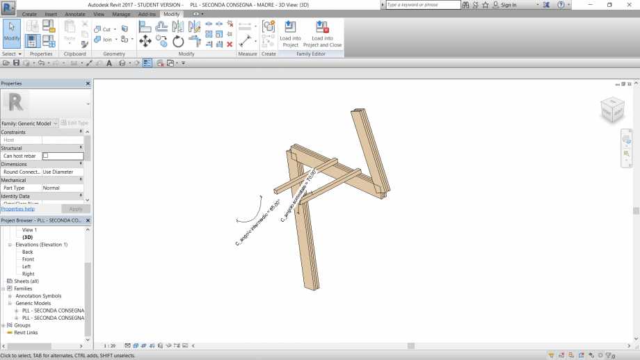
Caricamento delle parti figlio sul file madre
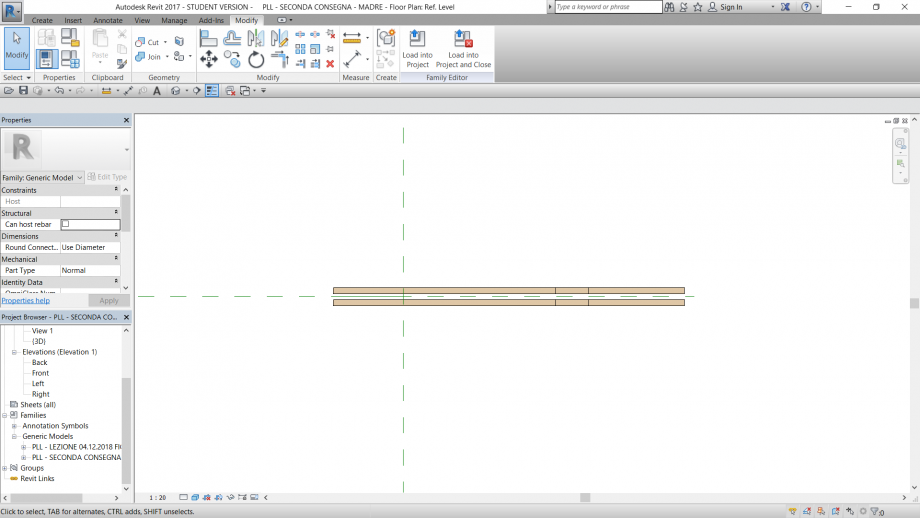
Carico dapprima il file FIGLIO 1.
Con il comando set - pick a plane mi posiziono in relazione alla ref. line rispetto alla quale voglio che la parte si muova.
Inserisco casualmente la coppia di aste, le allineo alla ref. line e ai punti estremi della ref. line.
Ripeto le operazioni per ognuna delle tre ref. line e verifico gli allineamenti modificando i parametri angolari.
Successivamente carico il file FIGLIO 2, e procedo allo stesso modo che con la parte 1.
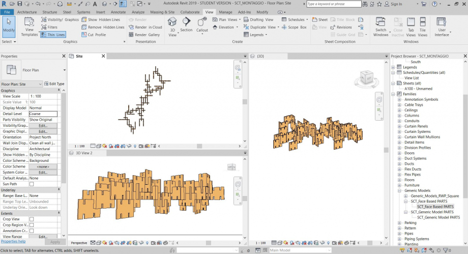
PROJECT
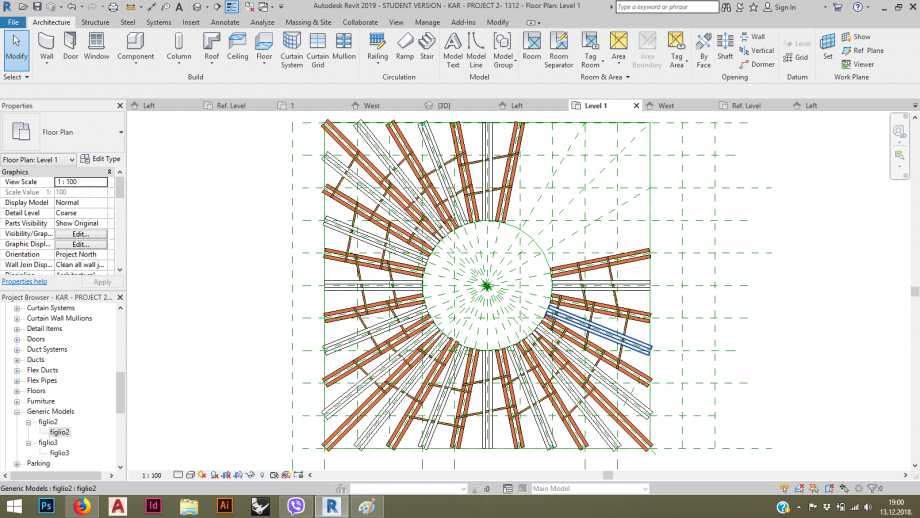
Tramite i ref. plane genero una sequenza di assi regolare e su di essi posiziono il file MADRE, variando la posizione lungo quell' asse così da ottenere un' andatura ondulante. Specchio gli oggetti due volte.
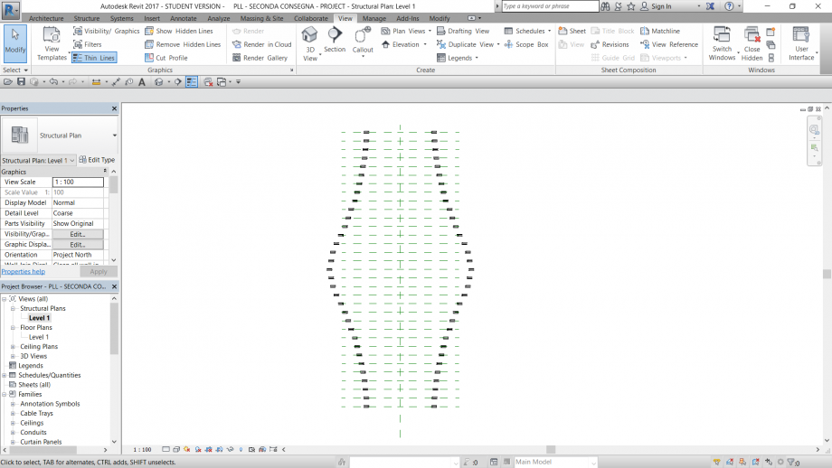
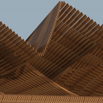
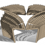
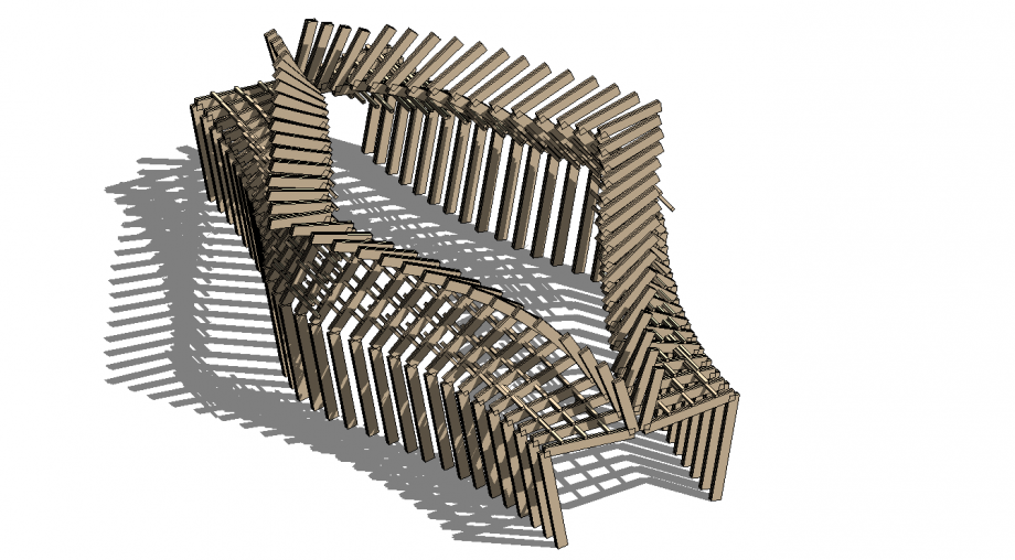
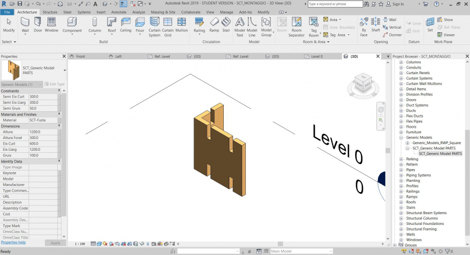
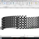
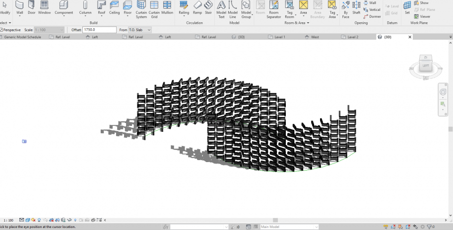
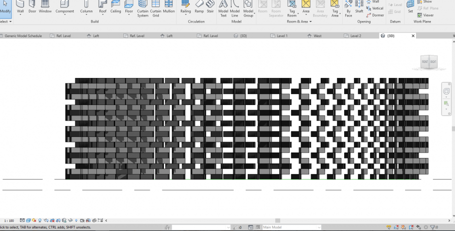
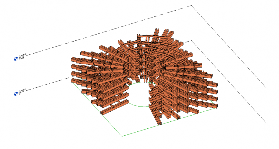
Questo è il primo risultato in 3D:
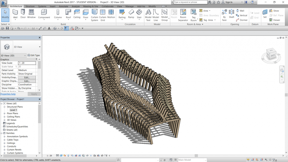
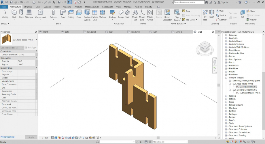
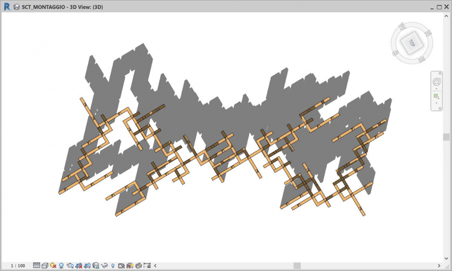
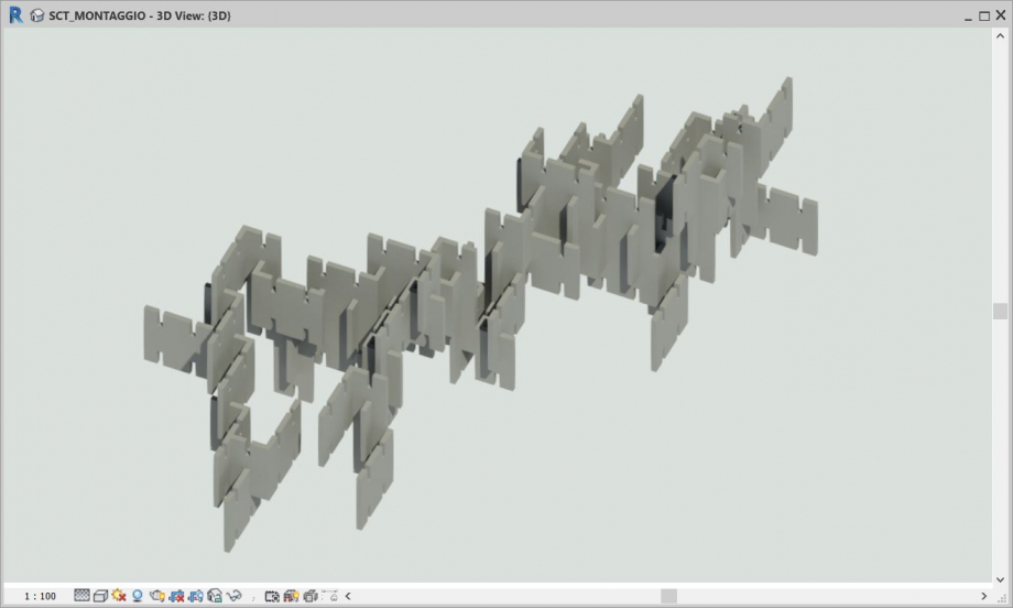
Aggiusto la posizione dell'asse centrale e con il comando schedule / quantities - generic models - gestico i valori degli angoli costruiti nel file MADRE.
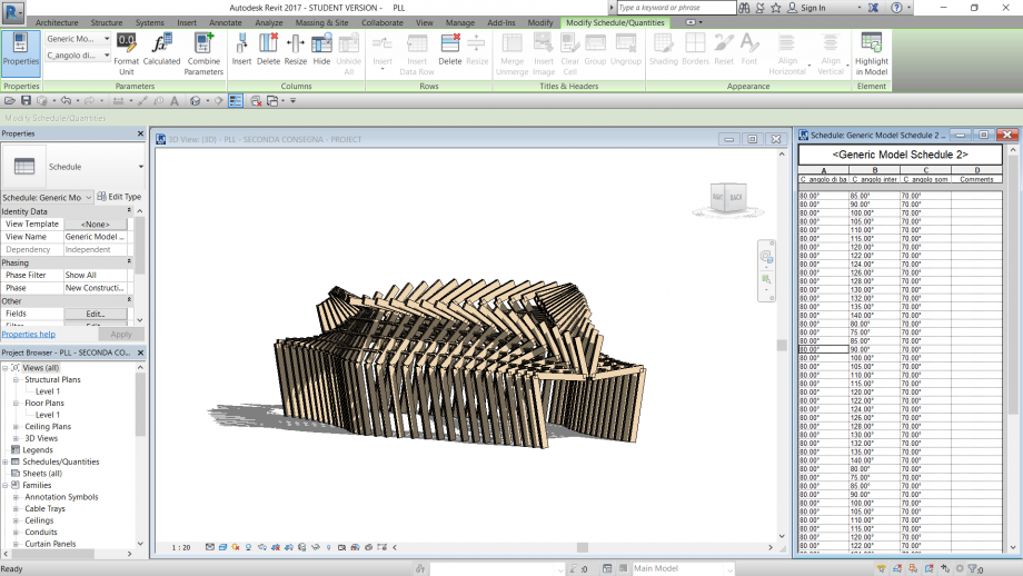
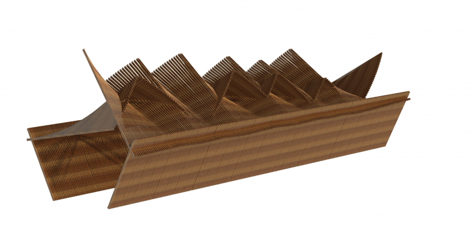
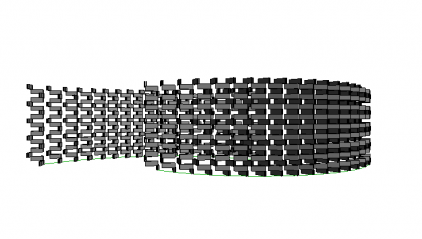
Questo è il PROJECT finale:

 sergi.caralt
Ven, 14/12/2018 - 01:13
sergi.caralt
Ven, 14/12/2018 - 01:13
1) Apro "Metric Generic Model"
2) Faccio una parte parametrica
3) Apro un nuovo "Metric Generic Model face based"
4) "Load into Project" e lo metto nel punto piú comodo per lavorare dopo sul progietto
5) Apro un nuovo "Project"
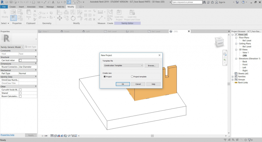
6) "Load into Project"
7) "Load into Project" e inizio il montaggio
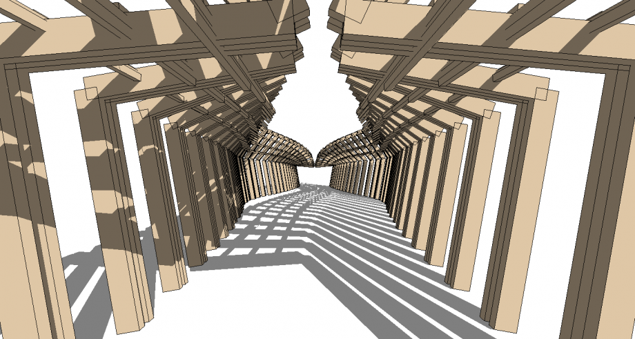
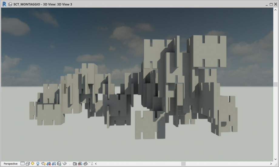
8) Faccio diversi punti di vista per spiegare il progetto
 pg1038
Gio, 13/12/2018 - 20:08
pg1038
Gio, 13/12/2018 - 20:08
For this assignment we had to create a tectonic form by using parametric design.
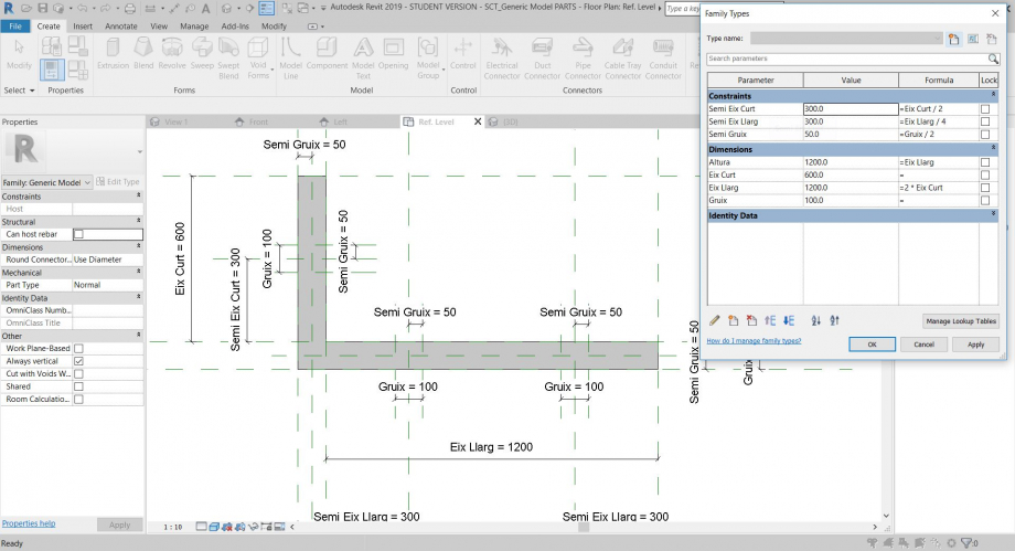
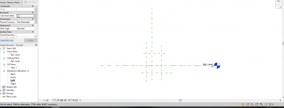
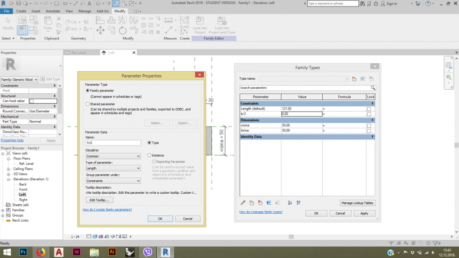
First i made a femily using generic model line based. I made reference planes in order to achieve a central - based object. I worked in left view.
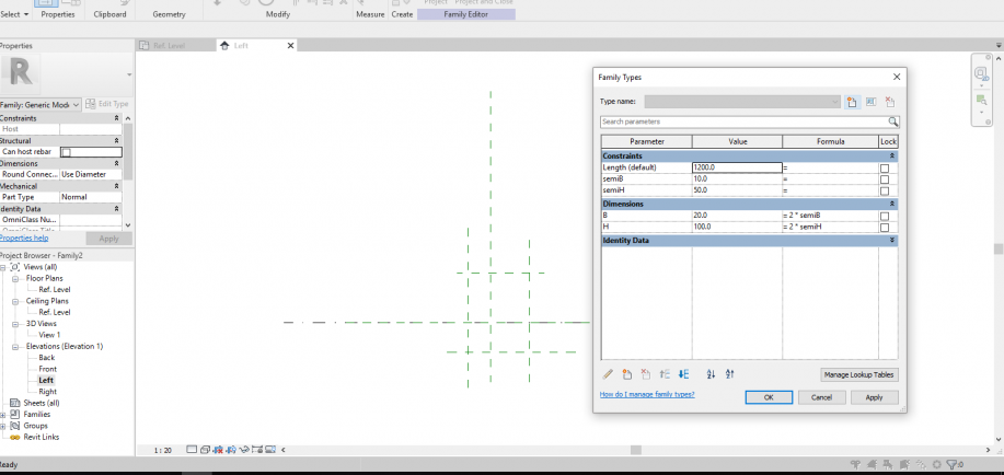
In order to control distances i quoted distance between reference lines and existing lines, made them parameters and another parameters with formula.
Once i had reference geometry i made an extrusion above geometry and aligned it to reference planes.
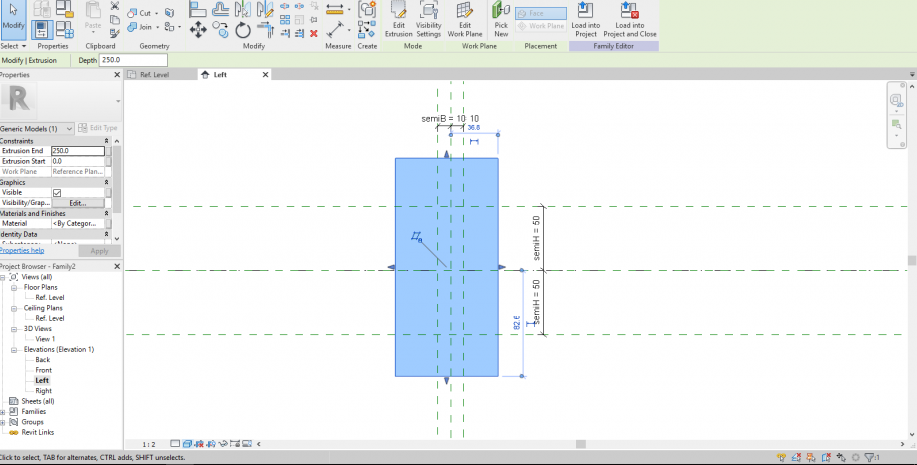
 I aligned it also in ref.level to existing parameter.
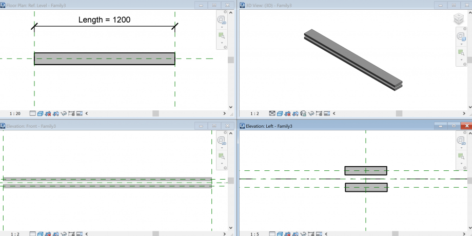
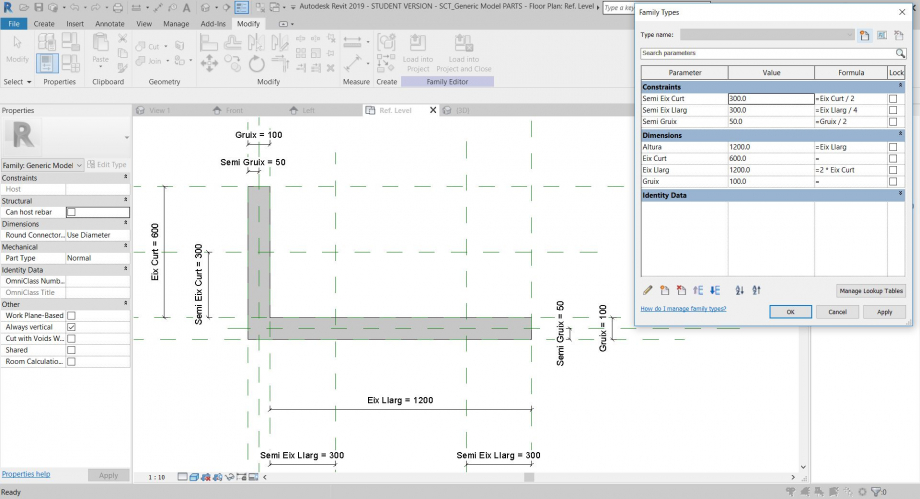
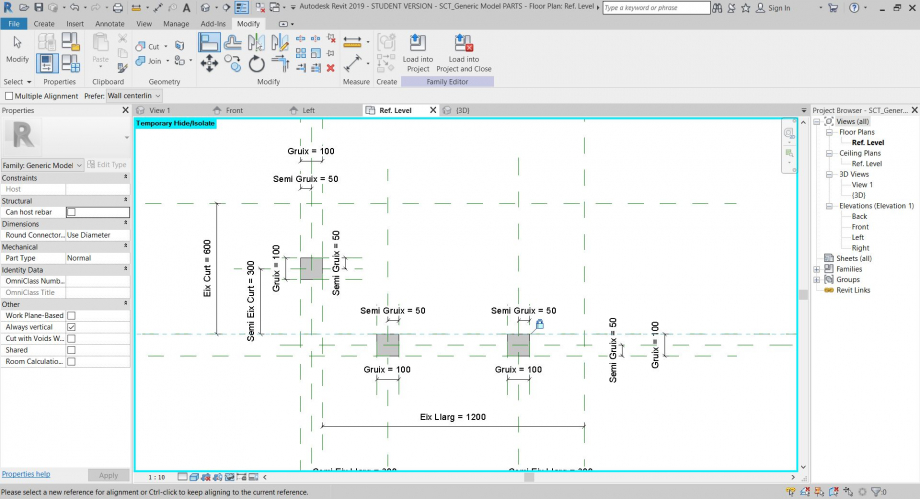
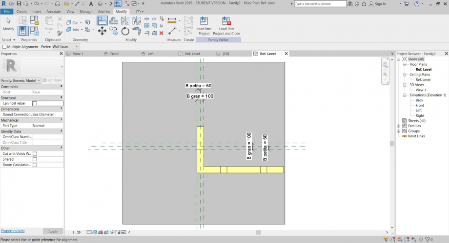
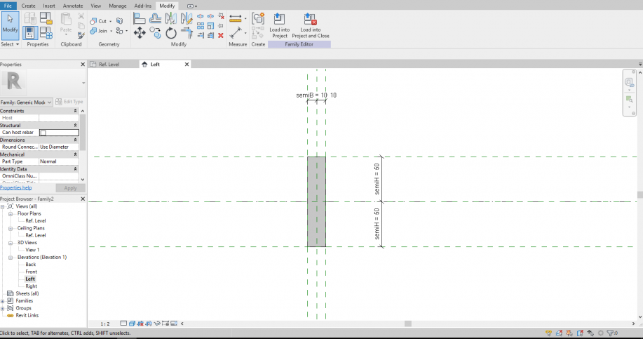
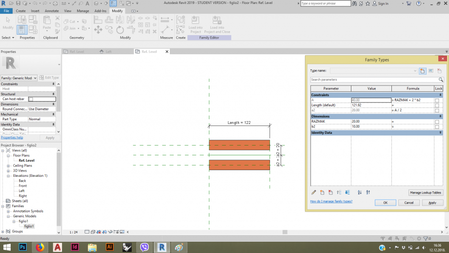
Once i had this object i wanted to make two paralel objects in another family. So i opened a new line based generic model. I made two reference planes, one under and one above the existing line.
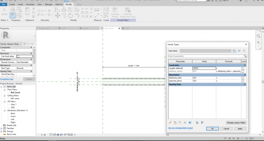
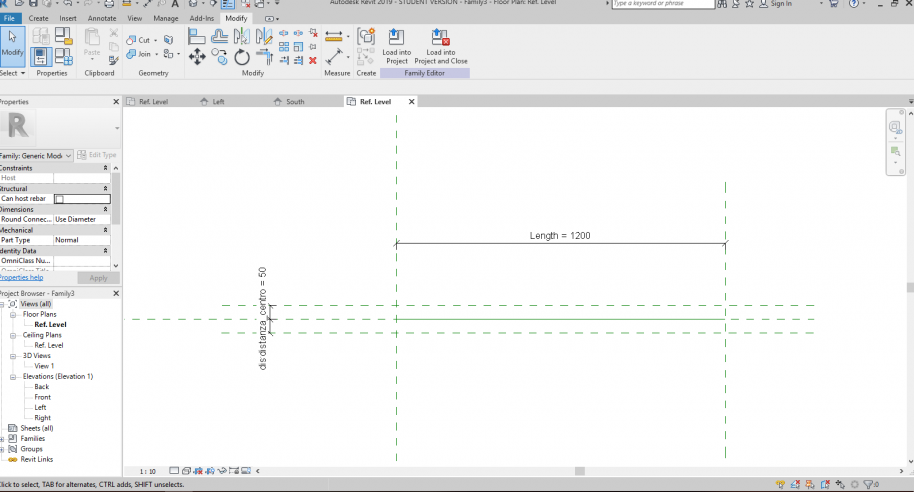 AAs i wanted to control the distance between them i quote distance between lines and made them a parameter. The probelm was that this parameter control only the distance in between axis of objects and not actual distance. In order to fix that issue i made another parameter which represents distance from centers without the thicknes of objects. I managed to do this with formula.
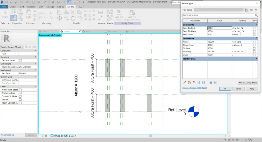
Knewig that i would need this two objects aligned in the bottom of them and not in the centre i aligned it in left view. In that way i would have more controle on it when making a project.
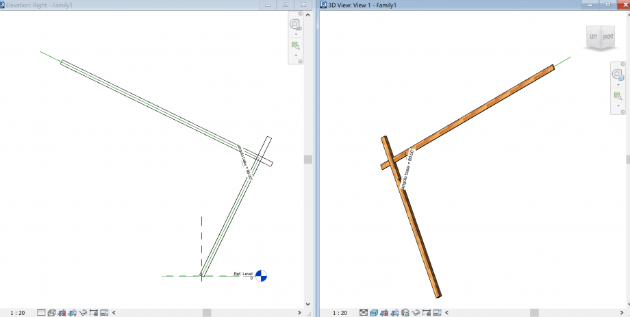
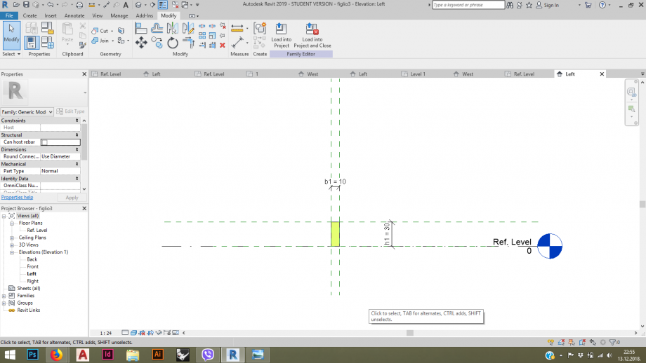
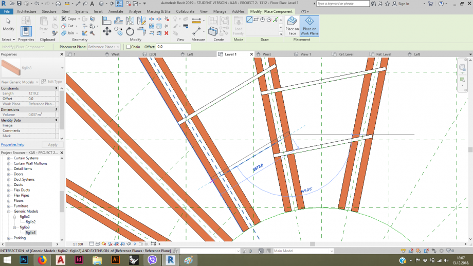
Next, i opened new family, this time only generic model. I wanted to have control on angle of object in floorplan. This time i made a reference line from center of existing reference planes. I quoted angle between them and made new parameter - shared parameter of instance.
Than i loaded previous family into it and aligned it onto reference line. In that way my object was moving with the line when angle changed.
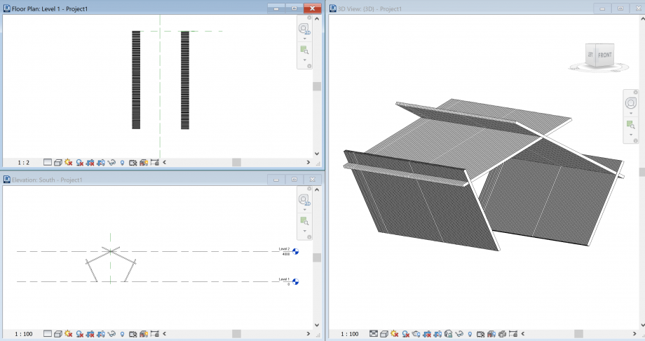
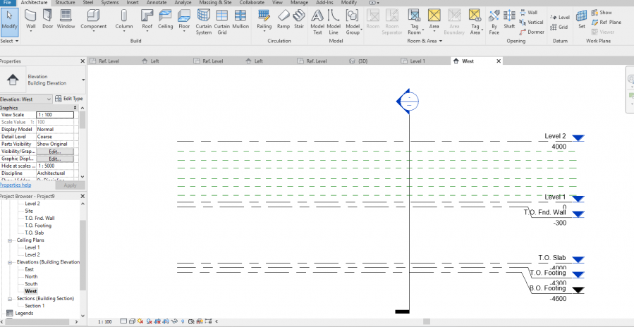
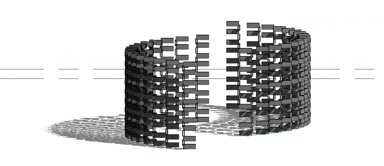
This is my final family. I opened a new project and made a reference geometry. First in side view (west). I also named each plan so i could use them later as a work planes.
Then i made reference geometry in floor plan by using reference planes and model line, which i used because i wanted a curved shape of new composition.
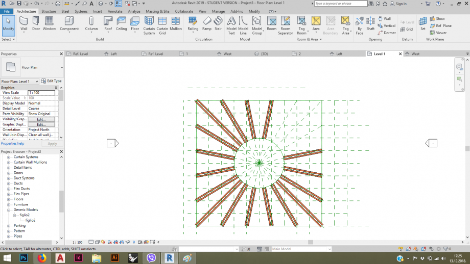
Once i made all the references i need i load last family into project and starting placing it into work plane. For each level i had to make a new work plane which refers to reference plane in which i want to place my objects.
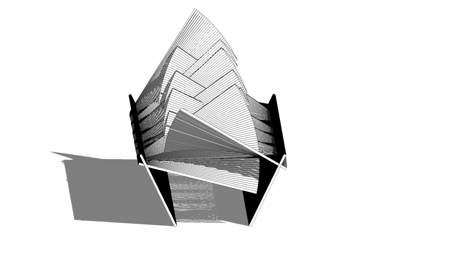
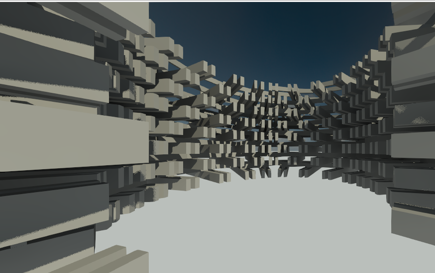
 Since i have shared parameter for controling the angle i used schedule. I rotate the object by 10°, from 0° to 30° and prom 90°to 60°, depends on level. In this was i achieved textile like tecture.
At the end i aligned reference planes on above another so every part of my composition has a support.
 Like last time, i had problems with shadows, i figured out that they were below level 1 so i relocate them under my object on level 1.
Gio, 13/12/2018 - 23:41
 karla.ritosa
Gio, 13/12/2018 - 21:47
karla.ritosa
Gio, 13/12/2018 - 21:47
Ciao, for second exercise, first what I did it was open Family- Generic line based in which I make parametrical object centered on a reference level (with new ref. planes and formulas in Family Types)
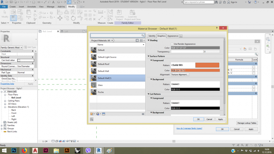
Then, for material of the object I made new parameter (material) and clicked on three dots hidden on <by category>, then a new window pop out where I choose default wall (duplicate it!) and then choose solid fill and color. My object is made from wood.
Then I open new Family Generic line based, made two reference planes and insert my first Family into to make a new object with previous object. And formals are providing me to change distance between two objects which are also centered.
For my project I did another parametrical object also in wood
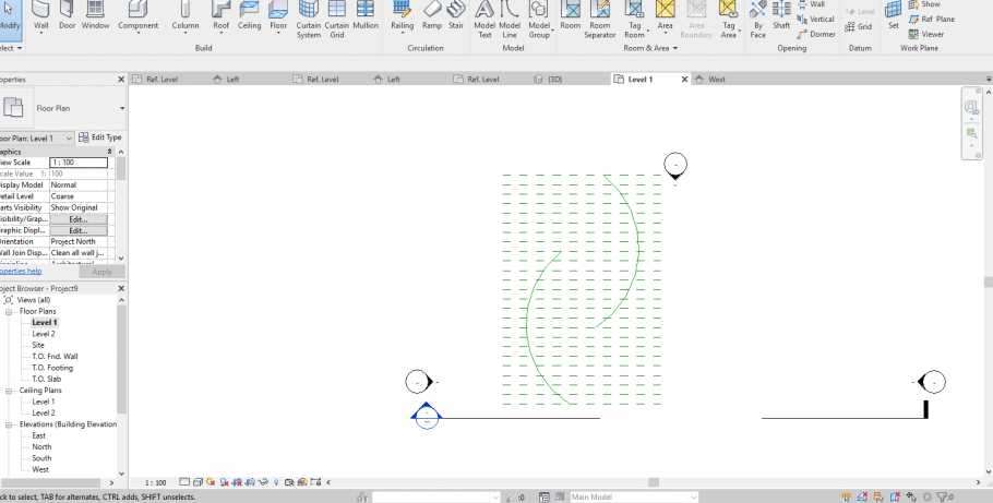
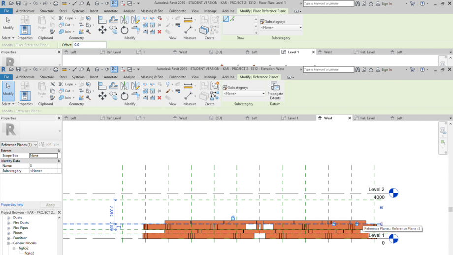
After, I opened New Project and in side view (west) i did reference plans between to Levels, and I gave them a name (1,2,3..) just to be easier. Then I went on view Level 1 , where I did my fundamentals for going forwards (all with reference plan and modal line). I insert my objects on Level 1 in order that I want, then I went to Architecture - Set - pick a plane -(my reference plan:1) and then I was inserting another object to this level, in a side view I moved reference plans to be one on another
.
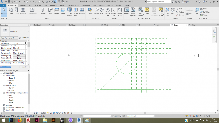
Level 1:
reference plan 1:
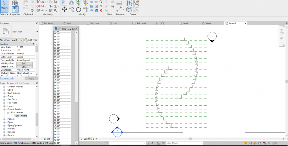
reference plan 3:
Reference plan 4:
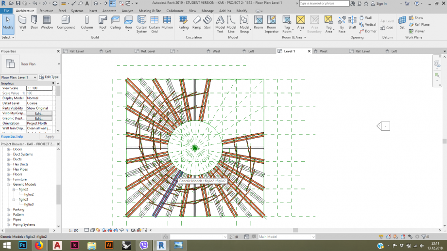
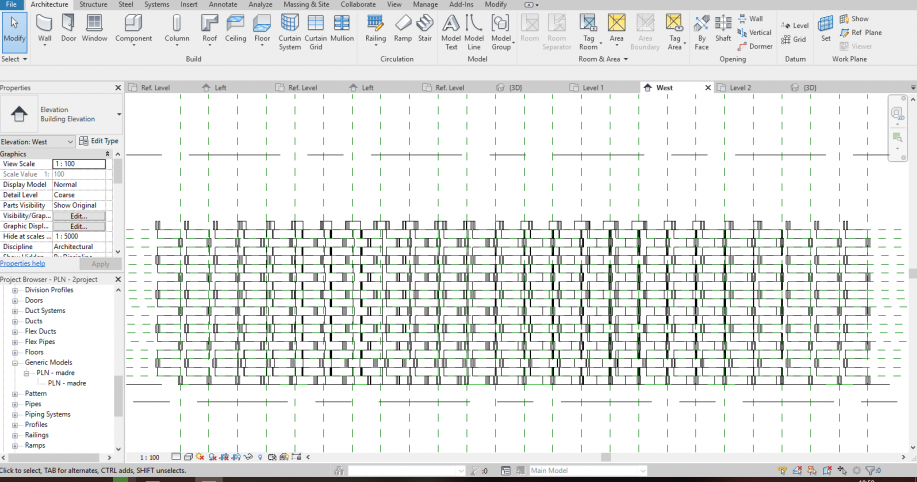
side view:
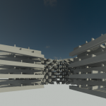
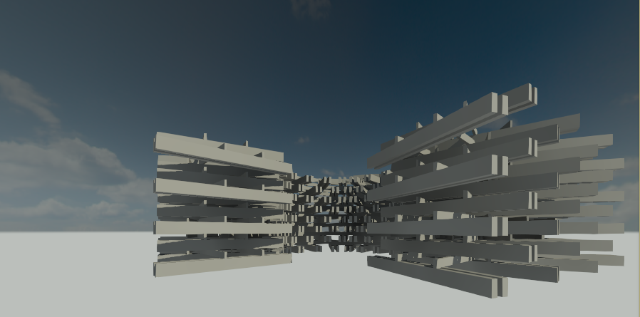
3D view:
Gio, 13/12/2018 - 23:41