


 Emmeline_Germaine
Lun, 23/03/2015 - 22:17
Emmeline_Germaine
Lun, 23/03/2015 - 22:17
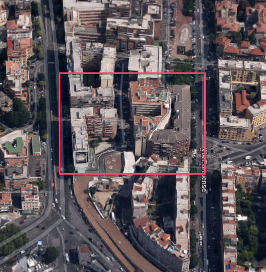
We choose to work on two buildings iin Via di Trastevere, near from our project site.
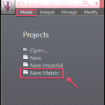
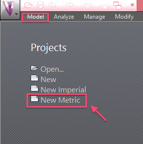
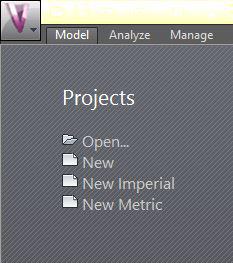
Step 1: Opening and Setting / Start Vasari / On the Homepage "New Metric"
We open an empty space with metric system units.
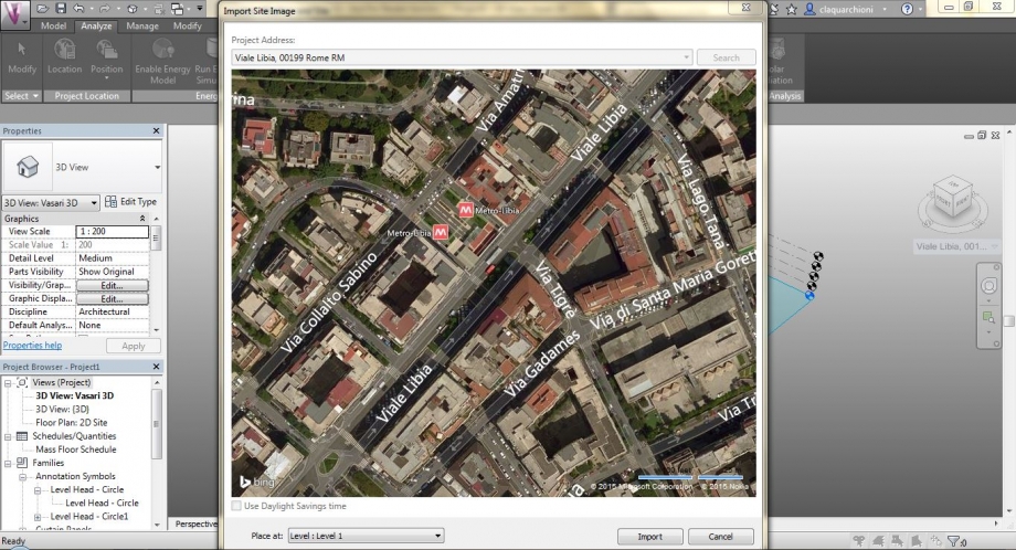
Step 2: Setting a Location / Analyse -> Location -> entrer the adress.
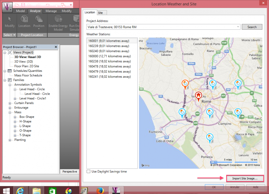
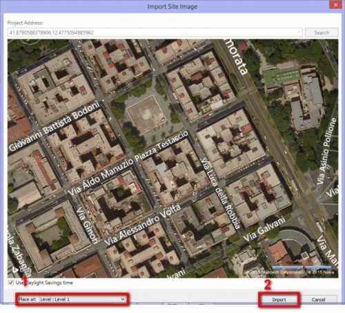
Importation of the image of the site. Be careful to import the image on the ground level.
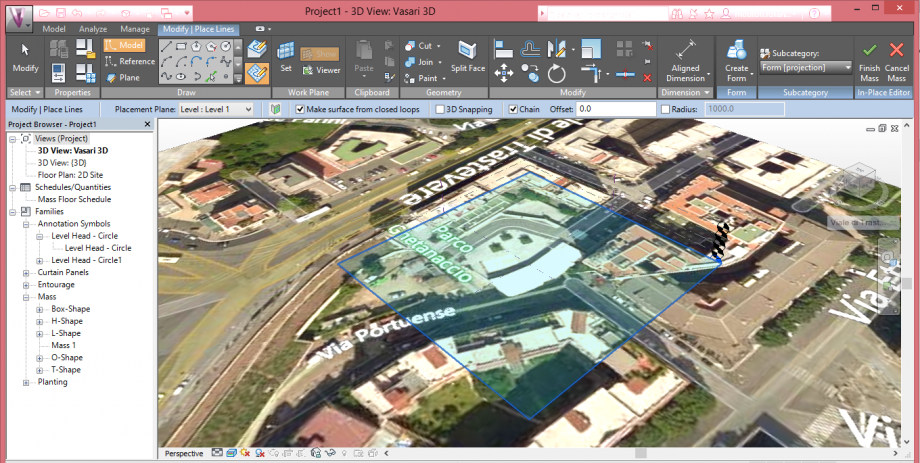
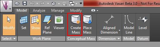
Step 3: Drawing the plan for modeling the globale shape of our buildings
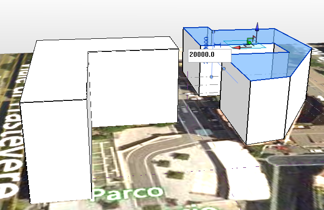
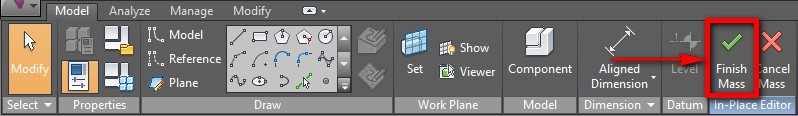
Model / Create mass / Draw it with the exact width, height and depth / Finish mass
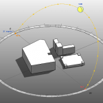
Step 4: Set Solar Analysis
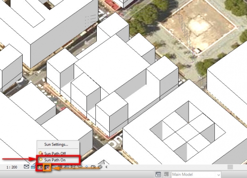
Activation of "Sun Path On" and "Shadows On" buttons.

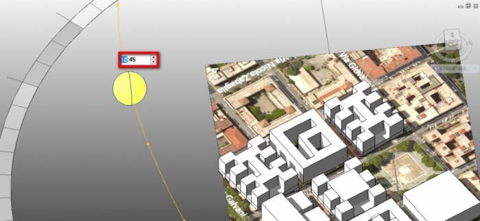
Definition of the date and timeperiod of our analysis.
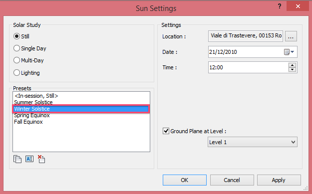
Step 5: Differents Sun Settings
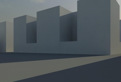
1/ Winter solstice at 08:00
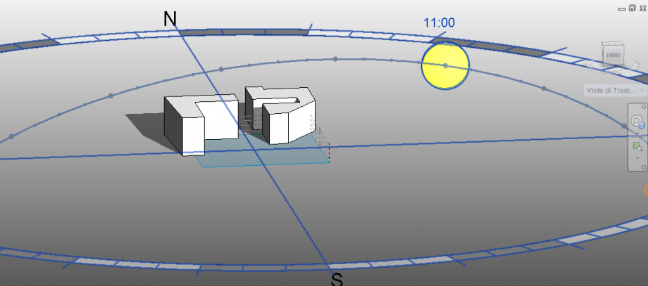
2/ Winter solstice at 11:00
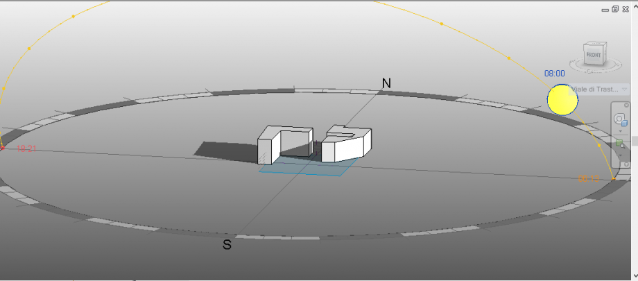
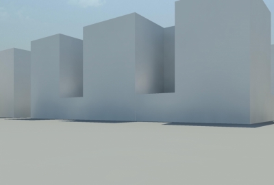
3/ Summer solstice at 08:00
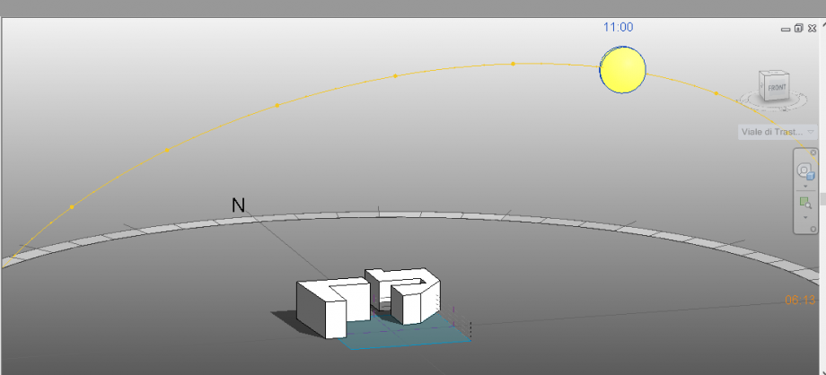
4/ Summer solstice at 11:00
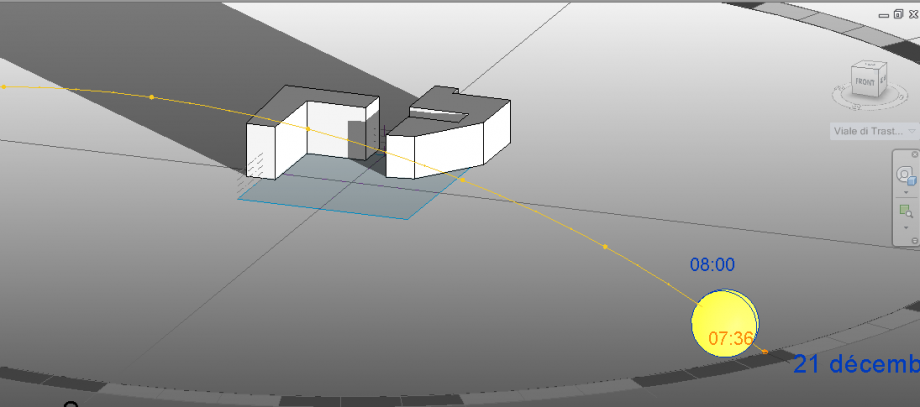
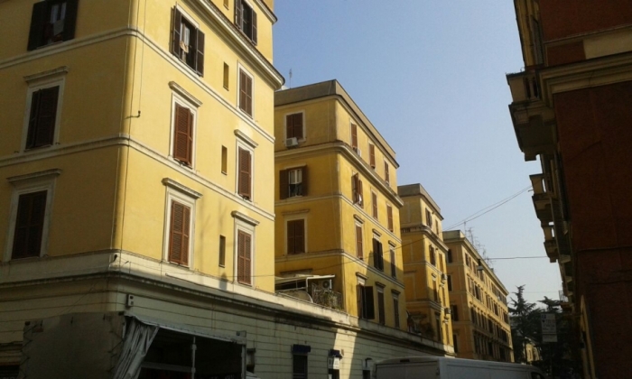
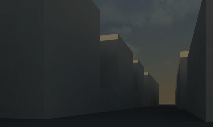
5/ At the same moment of the picture : Saturday 21rst of March, 08:00
6/ At the same moment of the picture : Saturday 21rst of March, 11:00
Finally we can observe the efficiency of the software to draw the shadows of buildings and on the buildings and their impact on the others buildings next to them. It could be useful for anticipate the height or the shape of our project and the shadows than draws on other buildings, for exemple, to give the same quantity and quality of natural light for every habitation.
Lun, 23/03/2015 - 23:12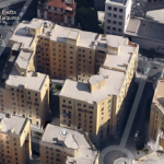 Salvador_Rodenas
Lun, 23/03/2015 - 22:16
Salvador_Rodenas
Lun, 23/03/2015 - 22:16
INTRODUZIONE
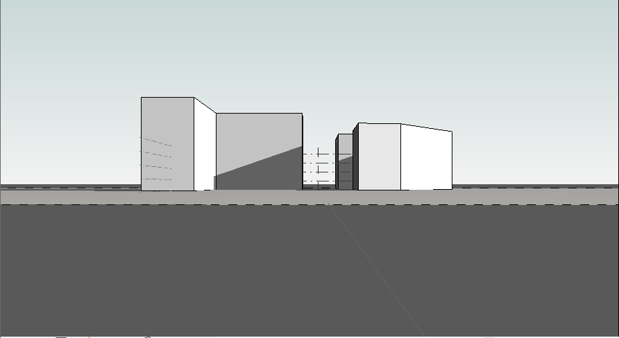
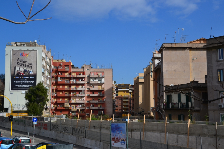
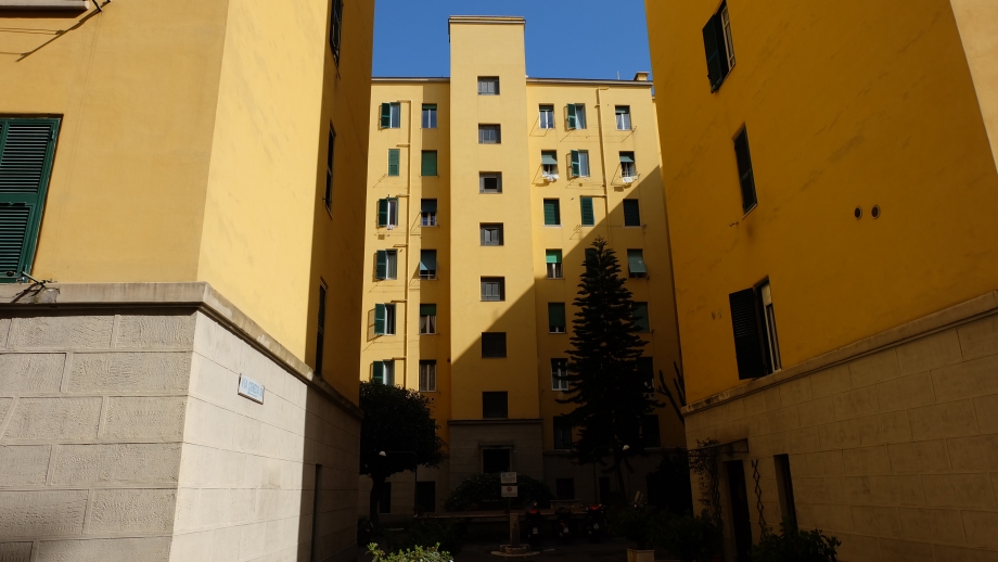
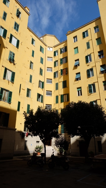
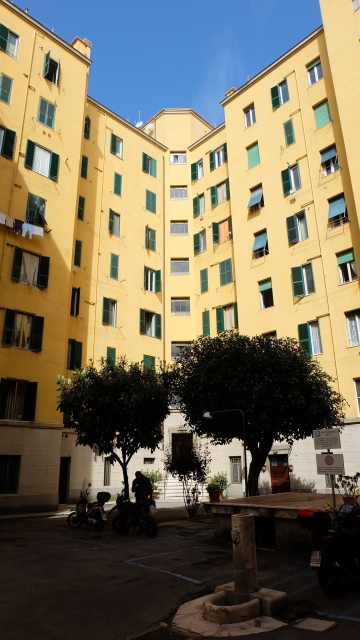
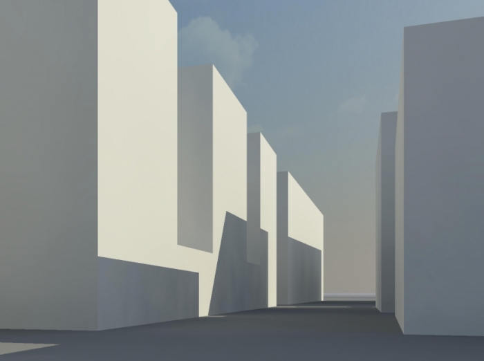
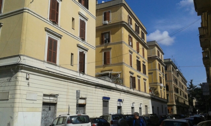
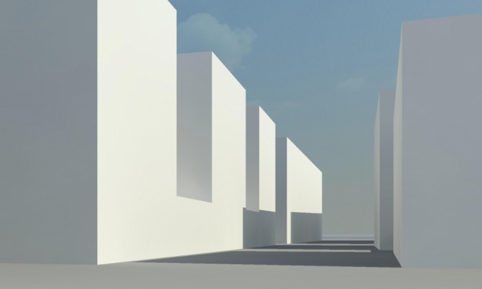
Farò lo studio di come si concentrano le ombre lungo una mattina in un edificio a Roma. Questo progetto sarà realizzato con l'aiuto di programma Vasari insieme con le fotografie scattate nel corso della mattinata.
AREA DI ANALISI
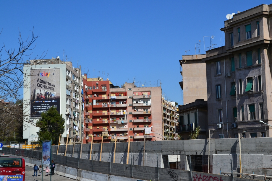
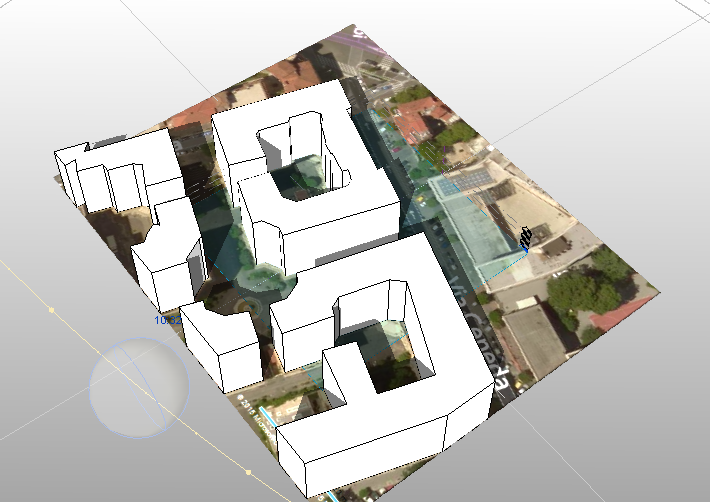
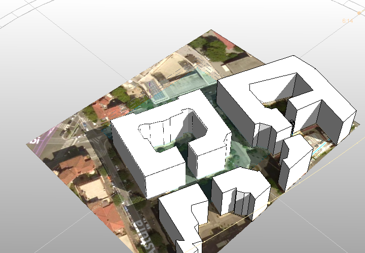
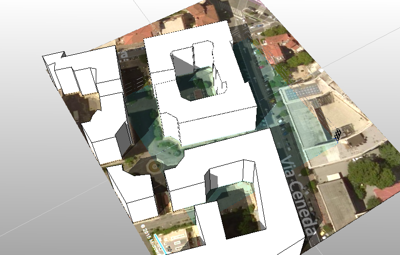
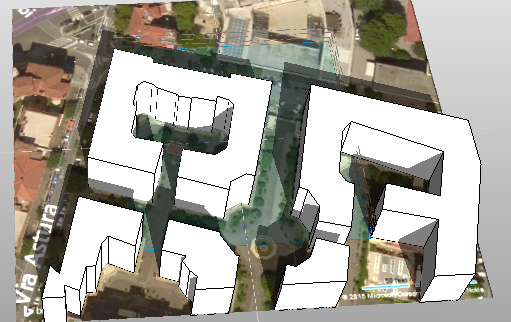
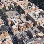
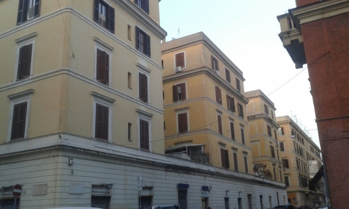
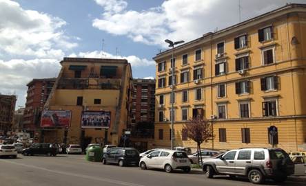
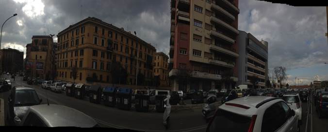
L’ area di analisi si trova a Via Ceneda, 39, vicino alla fermata di metropolitana Re di Roma.
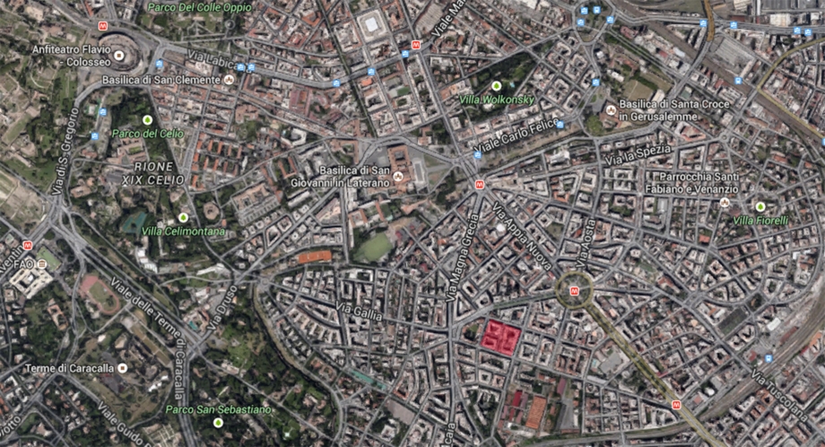
Roma.Questo quartiere è formato di quatro blocchi.
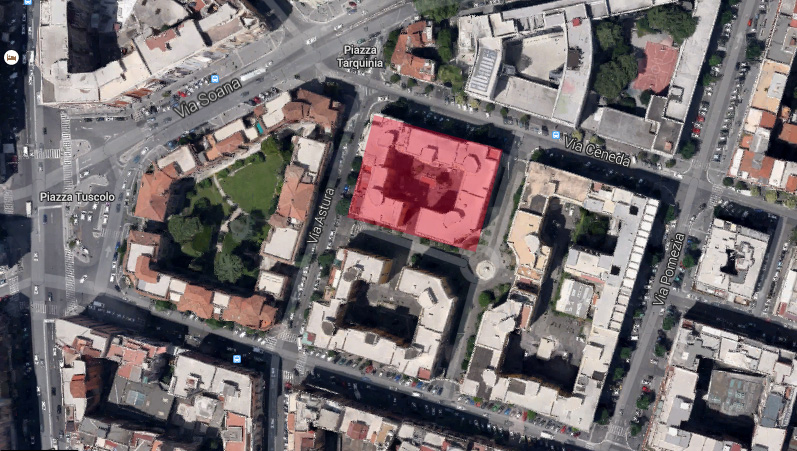
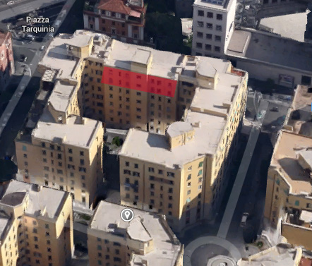
Vorrei affrontare un blocco di questo quartiere che composta di cinque palazzi diversi, studiarò il terzo di cinque palazzi.
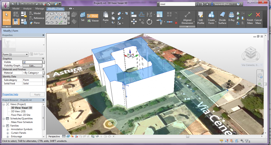
PROCEDURA PROGRAMMA
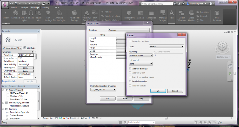
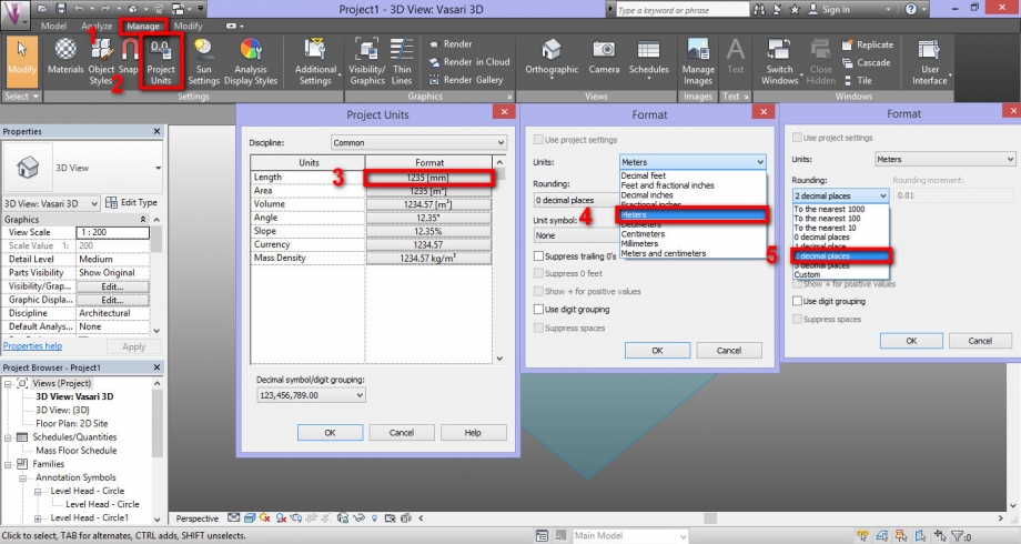
Prima di tutto, modifica della misura (a metri) PROPERTIES/ VIEW SCALE/ PROJECT UNITS/ FORMAT.
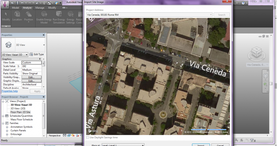
Secondo, ricerca della localizzazione del palazzo.ANALYZE/LOCATION/IMPORT SITE IMAGINE/ IMPORT (Level 1)

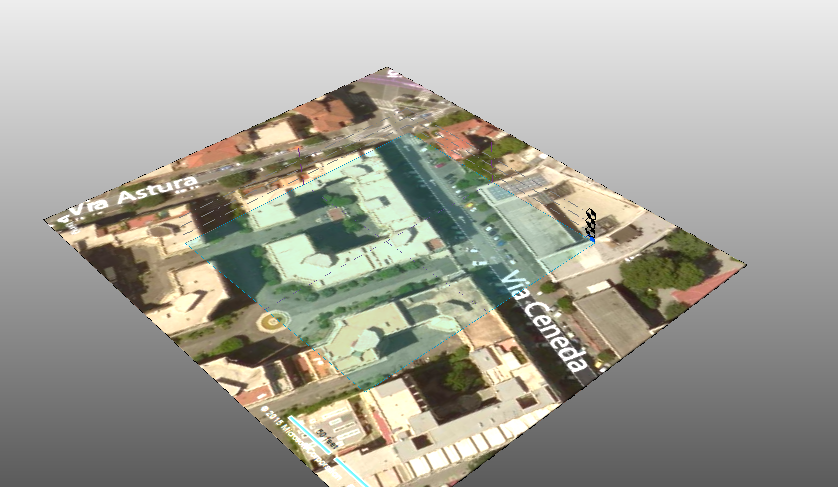
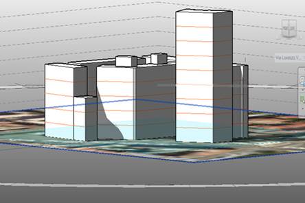
Terzo, dobbiamo mettere il volume del nostro palazzo. Altezza tra i piani è 3m, e ci sono 7 piani, altezza del palazzo è 21m. MODIFY|PLACE LINES/ MODEL / DRAW ON WORK PLANE.
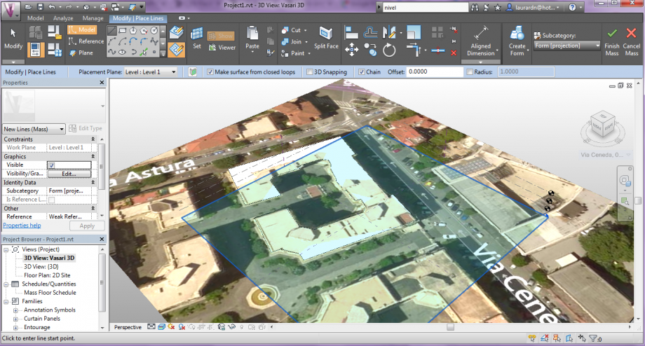
Per il volume: CREATE FORM/ SOLID FORM, mettiamo la misura di 21m di altezza.
Tutti i volumi adiacenti:
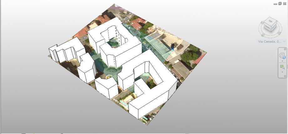
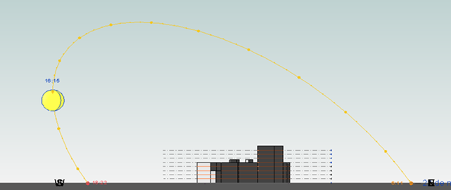
STUDIO SOLE
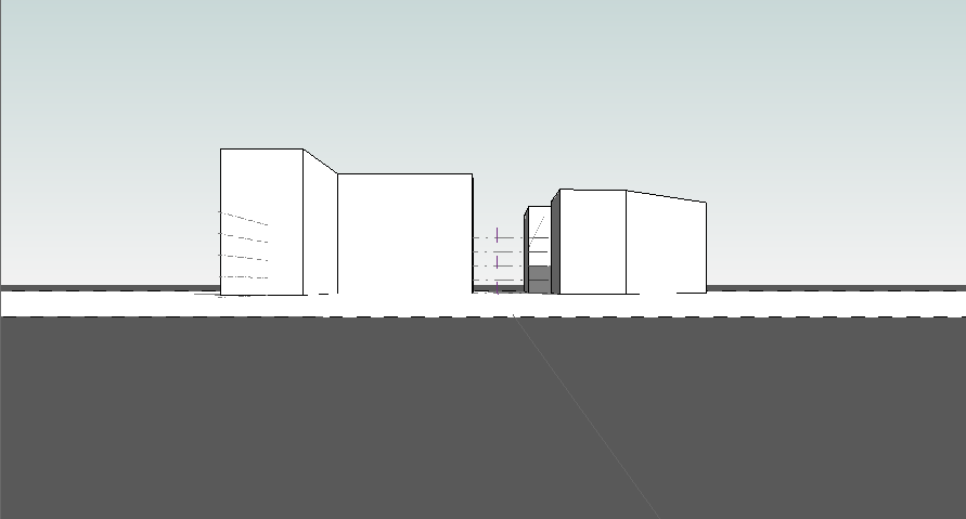
Procedere per controllare l’ ombre. Attivare SUN PART ON anche SHADOWS ON.
10:11
10:32
11:17
11:36
12:06
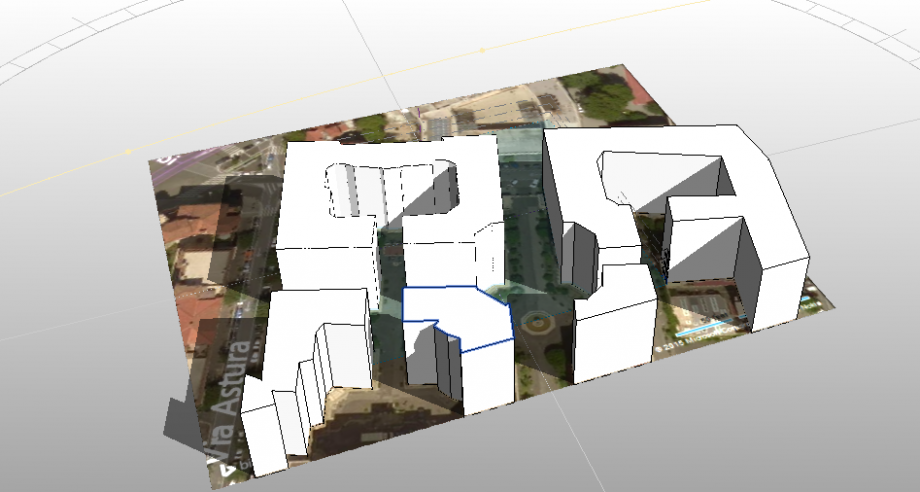
CONCLUSIONE
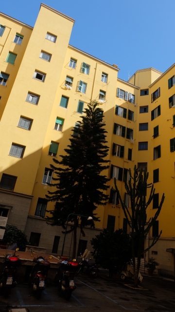
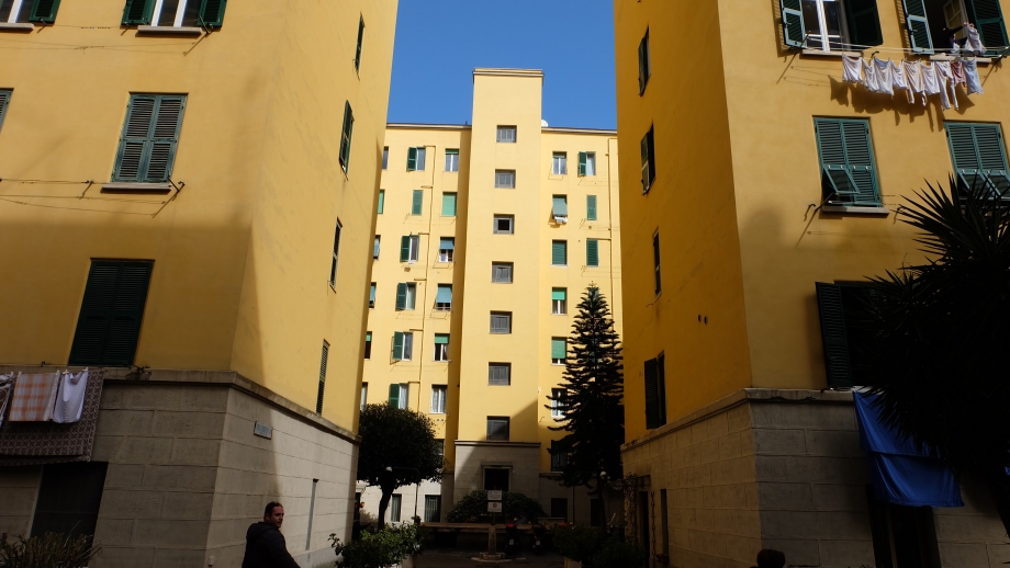
Possiamo guardare la coincidenza della programma con la realtà.
Verificare che il resto del area di studio rimane soleggiata durante tutta la mattina.
Comunque questi palazzi non sono ben progetatti perchè sono alti e sono molto vicino all'altro cioè solo i piani ultimi ricevono il sole gli altri rimangono nell’ ombra, cosi al inverno il riscaldamento non é abbastanza che c’e molto fredo e i palazzi sono molto umiditi.
Lun, 23/03/2015 - 23:08
 Adamczyk_DeFlorio
Lun, 23/03/2015 - 23:23
Adamczyk_DeFlorio
Lun, 23/03/2015 - 23:23
The studied building is located in Testaccio, Rome, in via Alessandro Volta, 40. It is composed by ground floor with a series of shops and four level for apartaments. To create a ed model, we used Vasari, with this proceedings.
1_Open Vasari and click on New Metric to start modelling.
2_Before starting, we have to change some settings, to have more comfort.
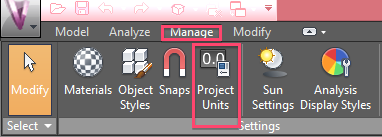
2a_Click on Manage, and then on Project Units to change the units from millimeters to meters.
2b_Click on Manage, and, on the right, click on User Interface. It’s possible to personalize the worksheet by clicking a series of options on th right, like in the follower picture:
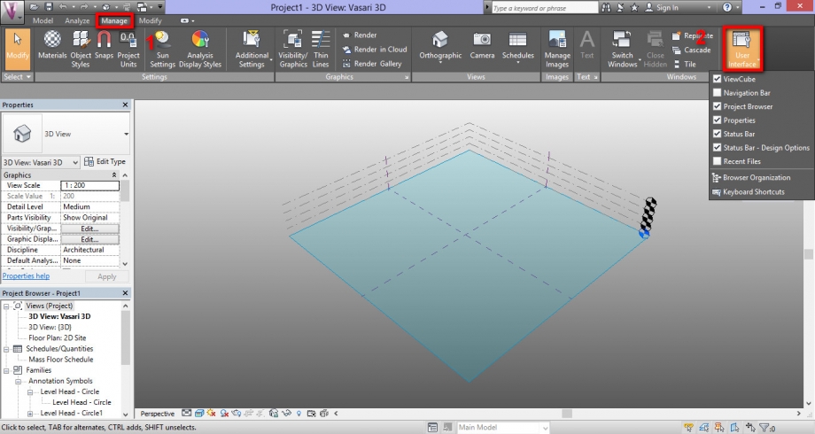
2c_Down on the left click on 3D View.
Done this, we can start our work.
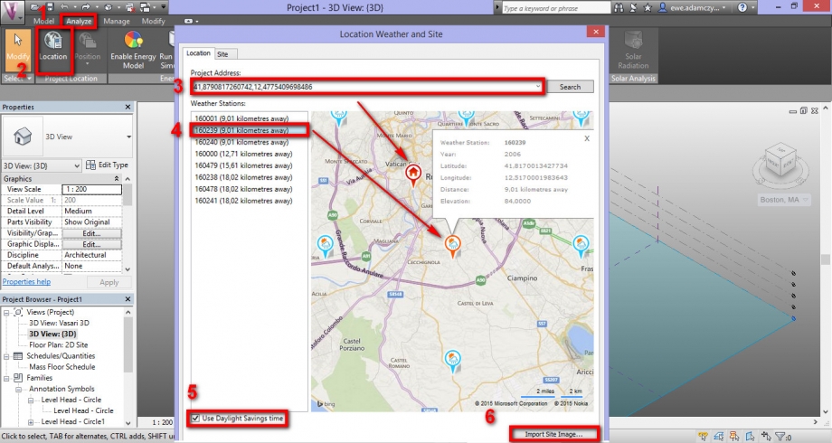
3_Click on Analyze and then click on Location to specify where the model is located. We need to set the weather center that is more similar to our building (short distance and same or similar altitude). Once you identified the position, click on Import Site Imagine to put this information on first drawing level.
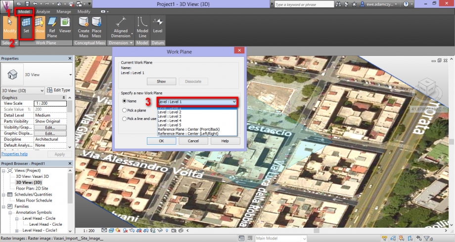
If we want change our level, we need to click on: Manage > Set > Work Plane. On last window, we have to definied the level on which we want draw, like in the follower picture:
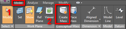
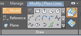
4_To draw the model, click on Model, and then on Create Mass. By clicking on one of the two icons near, it's possible to draw on worksheet or on the face of a building.
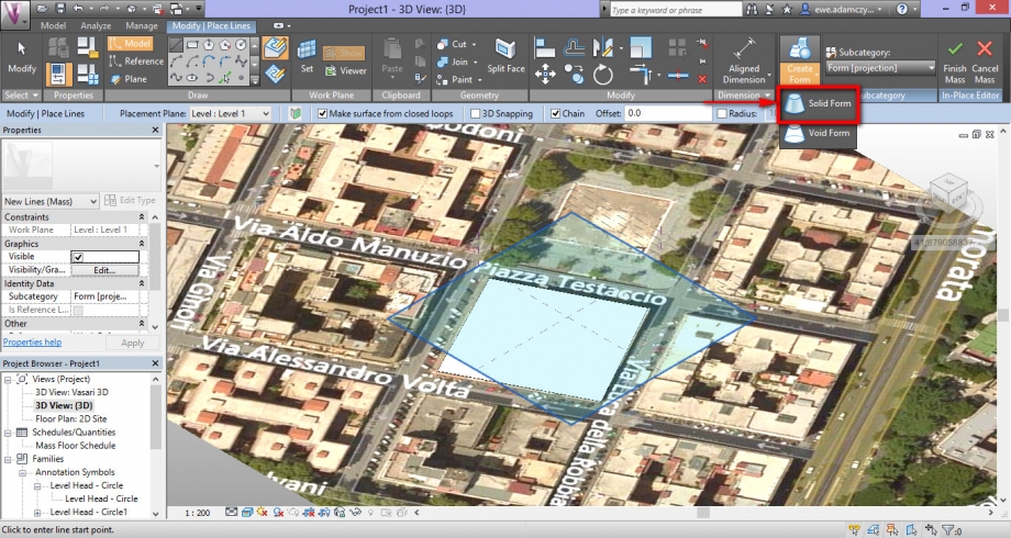
5_Once created the plan, click on Modify|Place Lines, and then on Create Form > Solid Form, to build the true form. You have to specify how tall is your building.
6_If your building have a courtyard, it’s possible to create it in your model by clicking on Create Form > Void Form. You have to specify how tall is the courtyard.
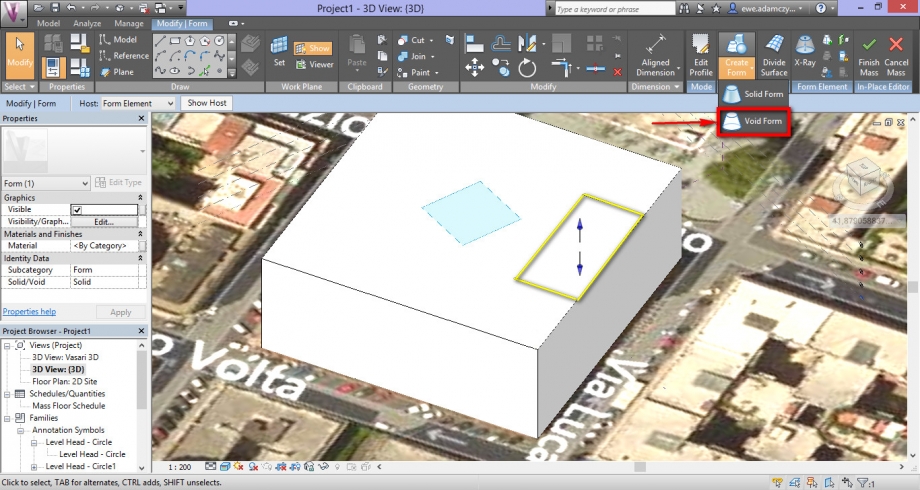
Once you finished the building, click on Finish Mass.
7_Now we need to set Solar time. For this, we have to click on Sun Path On. It will appear the daily solar route. On other hand, to activate shadows, we have to click on Shadows On. Now it’s possible to see where there is shadows on our model and how the models itself generates shadows on other buildings.
In this situation, wa have analized our building on 20 March, in three different moments of the day: at 09:00 a.m, 12:00 and 5:00 p.m. It is possible to set the time in Sun Settings.
To verify the correctness of our work, we compared renders (we look from the street) with the picture that we made on 20 March. To do this, you have to click on Manage > Camera > Render

Picture of south face at 09:00 a.m. :
South face at 09:00 a.m. :
Picture of south face at 12:00 :
South face at 12:00 :
Picture of south face at 6 p.m. :
South face at 6 p.m.:
Conclusions
The east face of the court, in which is located all bedrooms is located in a good point during all the day. In fact the zone doesn’t need a strong solar radiation. On other hand, this location allows to radiation to enter in bedrooms, through the fixtures. On south-east corner il located the kitchen withliving room on south west corner. This rooms is located on a good point too, because the radon is costant during all the day. In the end the building has a specular form. If on south face we have a favorable situation , on the north face , the situation is completely opposite , cause of energy problems and in some points, the presence of mold .
On the north side of the building chosen , is Piazza Testaccio . We thought it would be interesting to study the relationship between the square and the building ( north facade ) . In particular , during the summer solstice , the building does not create any protection on the square , as the shading is very low . In the winter solstice , however , the shadow of the building continues towards the square , obscuring an important part of it during the period in which there is the most need of radiation. We can conclude that the location of the building from the square was not designed according to the modern criteria.
Exposure north facade during the winter solstice and summer solstice:
Lun, 23/03/2015 - 23:05
 Gemmiti_Giubilei
Lun, 23/03/2015 - 22:03
Gemmiti_Giubilei
Lun, 23/03/2015 - 22:03
Vasari è un programma assestante per la modellazione 3D che ci consente di operare sulla parte energetica delle strutture, ad esempio, all'interno dei nostri progetti possiamo inserire fonti di calore e fonti eoliche.
Tramite il suo utilizzo possiamo sperimentare diverse soluzioni scegliendo infine la migliore.
Nell’analisi seguente, si è condotto, col l’ausilio del software, lo studio dell’ombreggiamento, considerando in particolare l’edificio situato a Roma, via Catania. Esso fa parte di un isolato composto da diversi edifici, presenta 9 livelli ed affaccia, oltre che su via Catania a nord, anche su via Giuseppe De Mattheis ad ovest.

Step 1
- Avviare Vasari
- Aprire un nuovo documento cliccando su “New Metric”

Step 2
- Cliccare su “Project Units” per cambiare l’unità di misura e passare quindi da pollici a metri.
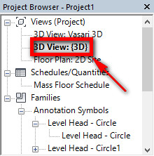
(Si consiglia di utilizzare la vista “3DView:[3D]”)
Manage>Settings>Project Units

Step 3
- Cliccare su “Boston, Ma” (a destra della schermata) e successivamente su “Set Location”

- Inserire l’indirizzo in “Project Adress”
- Cliccare su “Import Site Images”, si aprirà un’ulteriore finestra con l’immagine satellitare dell’area presa in considerazione.

- Cliccare su “Import” in modo tale da trasferire l’immagine sul piano di lavoro

Step 4
- Prima di iniziare a creare i volumi, è necessario impostare il piano di lavoro sul quale il software dovrà posizionarli. Selezionare "MODEL" nella barra dei comandi, cliccare su "SET" e nella finestra che si aprirà scegliere il livello desiderato.

Step 5
- Il passaggio successivo consiste nel creare il volume dell’edificio preso in esame.
- Cliccando su “Top” in alto a destra sul modello otteniamo la visuale in pianta e sarà più facile compiere le operazioni successive.
- Cliccare su Model>Create Mass

- Utilizzando il comando “Linea” possiamo procedere lucidando i contorni dell’edificio preso in esame e di quelli adiacenti.

- Una volta racchiuso il perimetro cliccare su Create Form>Solid Form per creare il volume dell’edificio.

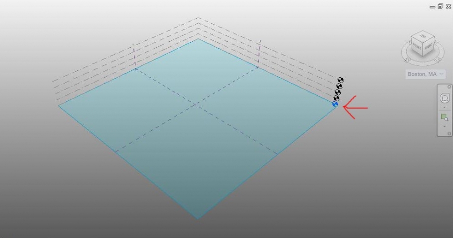
- Per modificare l’altezza degli edifici cliccare sull’asse z (freccia blu), estrudendo l’area precedentemente evidenziata fino all’altezza desiderata, oppure inserire la misura esatta nel riquadro dell’altezza.
- Cliccare su Model>Finish Mass per chiudere il modello.

- Con la stessa metodologia creiamo gli altri volumi.

Step 6
- Cliccare su “Sun Path On”, in basso sulla schermata, per attivare l'asse solare.

- Cliccare su “Shadows On” per attivare le ombre (icona a destra del comando “Sun Path On”)

Step 7
- Cliccare su “Sun Setting” ed impostare data e ora

Step 8
- Per ottenere l’immagine del modello relativa alla foto scattata in loco (con lo stesso punto di vista, data e ora) cliccare su Manage>Camera e posizionare l’icona sul punto di vista scelto.

Step 9
- Per ottenere un’immagine renderizzata cliccare su “Visual Style: Ray Trace”

Considerazioni
Abbiamo riscontrato che la facciata esposta a Ovest resta in ombra nelle ore mattutine, per poi essere completamente soleggiata nello ore pomeridiane, dato che l’edificio posto di fronte ad essa ha un’altezza discreta (circa 10 metri) rispetto ai 34 metri circa dell’edificio in esame. La facciata a Nord ovviamente rimane in ombra. Inoltre abbiamo riscontrato che la facciata a sud (gli ultimi 3 piani), che risulta essere soleggiata tutto il giorno, è cieca, ossia non presenta aperture che potrebbero giovare dell'esposizione. Questo ci fa pensare al fatto che non sempre alla base di un progetto vi è un ragionamento legato all'esposizione, facendo prevalere altre argomentazioni (condizionate probabilmente da normative).
Nelle ore pomeridiane l'edificio proietta la sua ombra sulla facciata della struttura posta sul lato opposto di Via Catania, ovvero a Nord dello stesso.
21 Marzo 2015 - ORE 10:30 21 Marzo 2015 - ORE 15:30


Lun, 23/03/2015 - 23:00
 Quarchioni_Puga...
Lun, 23/03/2015 - 23:06
Quarchioni_Puga...
Lun, 23/03/2015 - 23:06
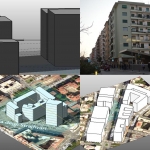
Analisi Esposizione Solare
Tramite il software Vasari, andremo ad analizzare l’esposizione solare, in diversi periodi dell’anno e in diversi orari di uno stesso giorno, di un edificio realmente esistente.
- Area analizzata 1 : Viale Libia, Roma
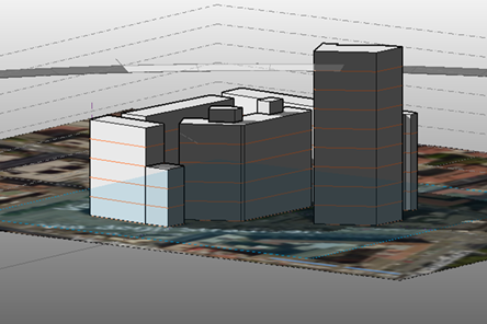
- Area analizzata 2 : Via degli Stradivari, Roma
STEP 1 : Impostazione del “foglio” di lavoro
1. Aprire Vasari, scegliere “New Metric”
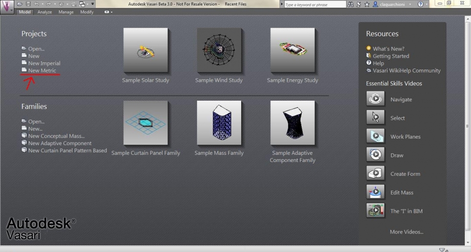
2. Impostare l’unità di misura che, di default, sarà impostata in millimetri
Scegliere MANAGE (1) à PROJECTS UNITS (2) à Scegliere l’unità di misura “metri”
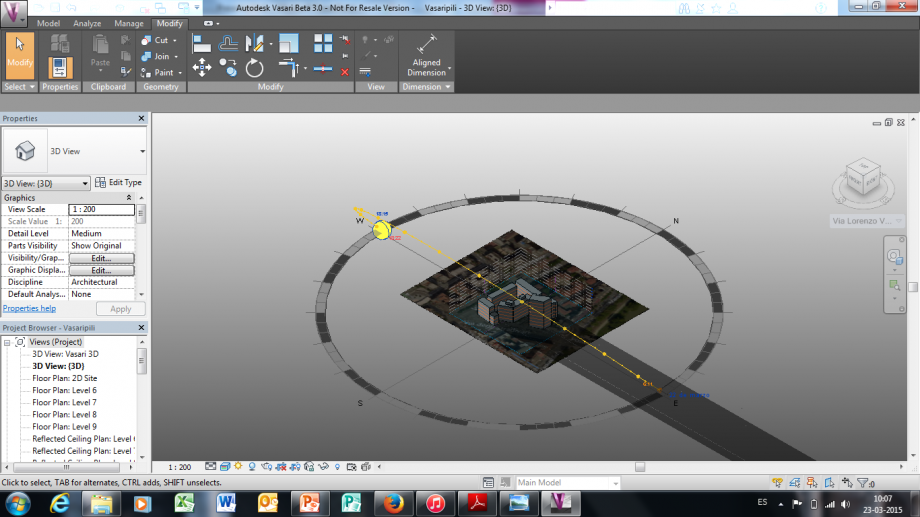
Possiamo notare a destra che la localizzazione geografica è impostata di default su Boston.
Quindi, dopo aver impostato il foglio di lavoro e l’unità di misura, il prossimo passo sarà impostare la geolocalizzazione dell’area di interesse.
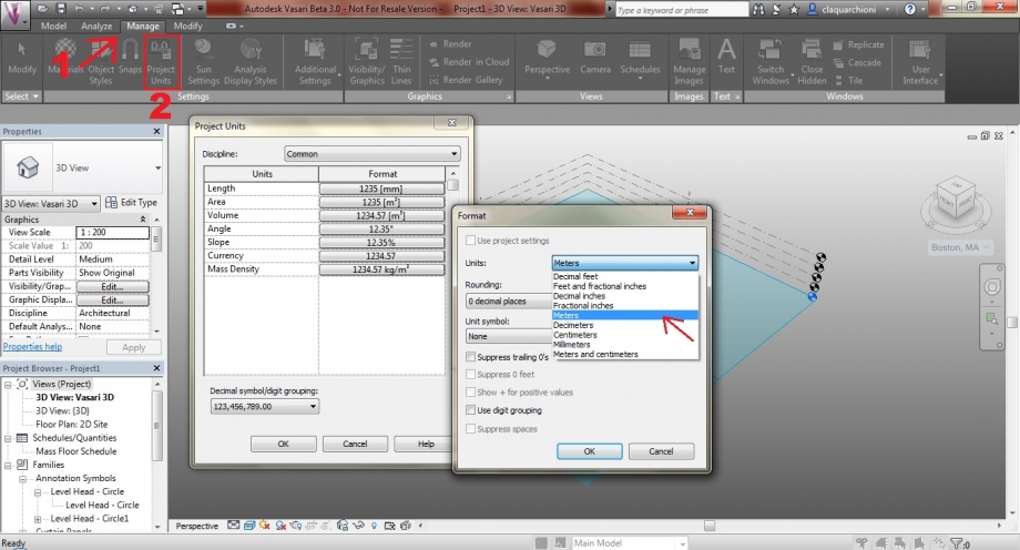
STEP 2 : Impostare la localizzazione geografica e importare l’immagine planimetrica dell’area.
3. Cliccare su ANALYZE (1) à LOCATION (2) e inserire l’indirizzo. Scegliere “Import Site Image”
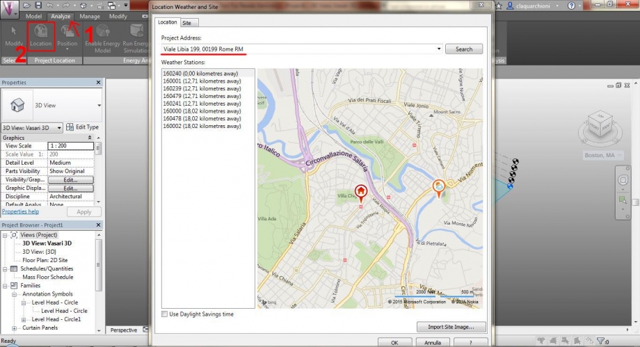
4. Una volta comparsa l’immagine satellitare planimetrica, si può procedere scegliendo IMPORT, controllando che il livello selezionato sia “Level 1” (ovvero il livello di terra)
STEP 3 : Modellazione
5. Per iniziare a disegnare un elemento scegliere MODEL à CREATE MASS
Inizieremo a disegnare la pianta dell’edificio per creare successivamente un volume elevandolo in altezza; è necessario quindi controllare di essere sul livello 1.
Nel caso in cui, si disegni ad un'altra quota, diversa dal “livello terra” , si può impostare il piano di lavoro desiderato su MODEL à SET
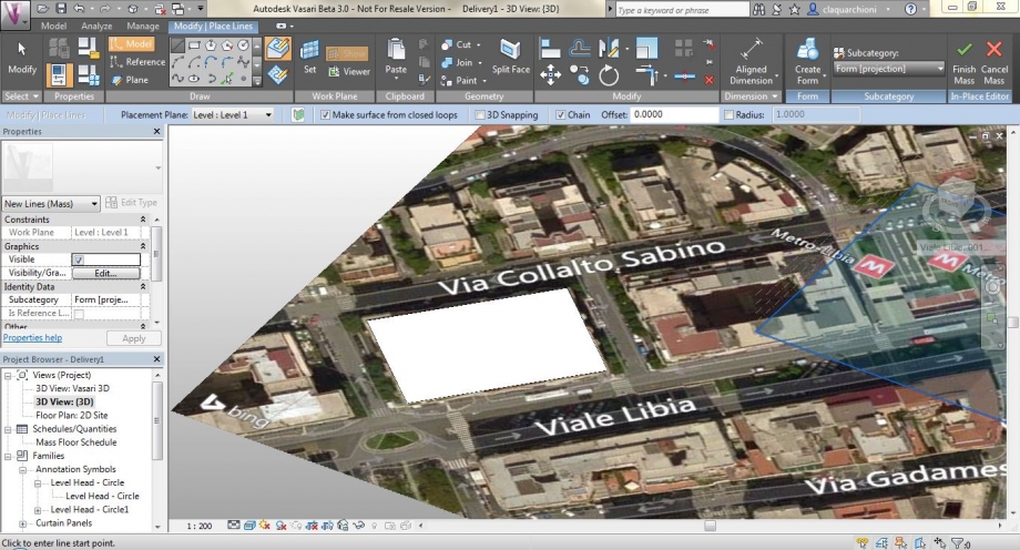 6. Per creare un volume, dalla forma geometrica appena disegnata, scegliere CREATE FORM (1)à SOLID FORM.
E’ possibile regolare l’altezza tramite le frecce delle coordinate in alto, o inserendola direttamente manualmente. L’edificio da analizzare è un edificio a 8 piani, il cui piano terra è occupato da esercizi commerciali. E’ stata inserita quindi l’altezza di 30 m.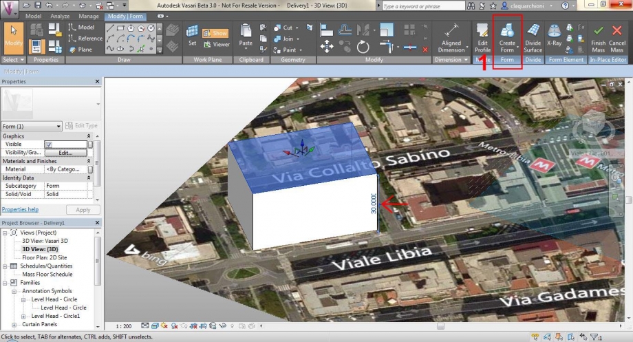
Una volta terminata l’operazione cliccare su “Finish Mass”
7. Si prosegue nello stesso modo per modellare tutta l’area da analizzare:
Area 1 :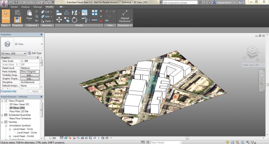
Area 2 : 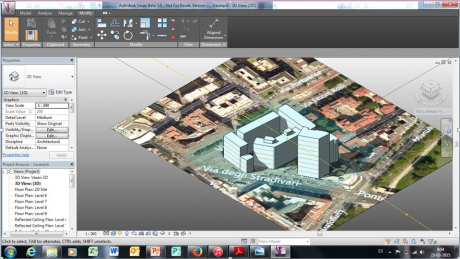
STEP 4: Studio dell’esposizione solare e delle ombre
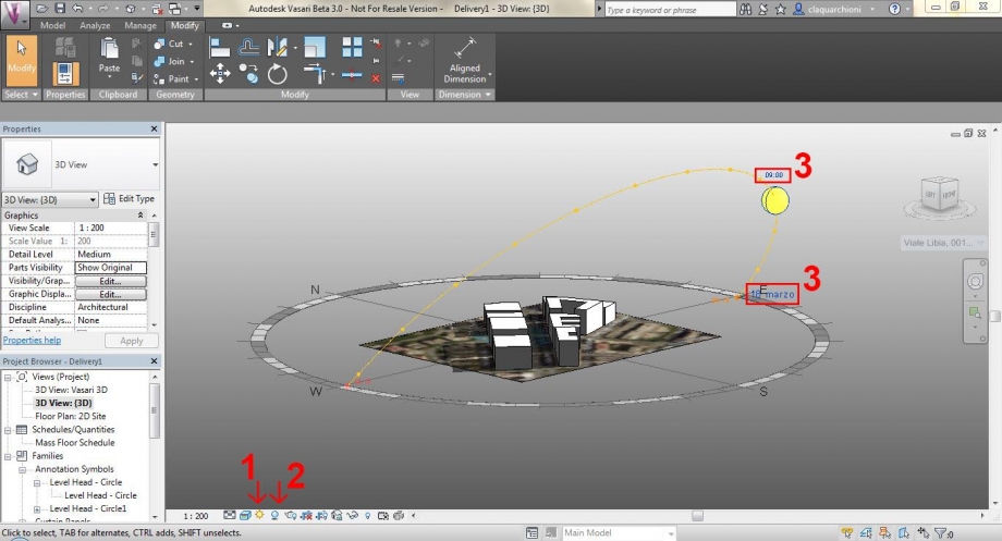
8. Per prima cosa, per analizzare l’esposizione solare dell’area d’interesse, è necessario “accendere” gli strumenti Sun Path e Shadows.
Quindi impostare su SUN PATH ON (1) e SHADOWS ON (2)
Infine scegliamo il GIORNO e l’ORA che vogliamo analizzare (3)
9. Analisi Area 1
Giorno : Mercoledi 18 Marzo
ORE 09:30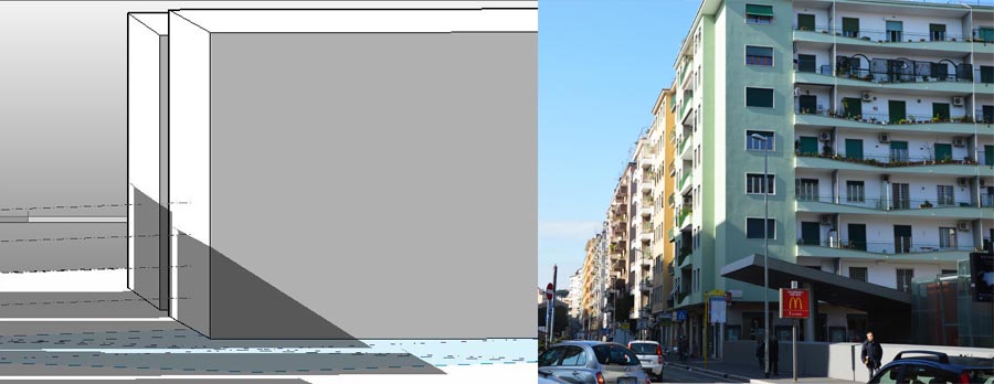
ORE 13:30
ORE 17:30
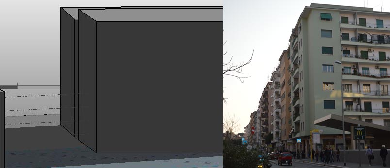
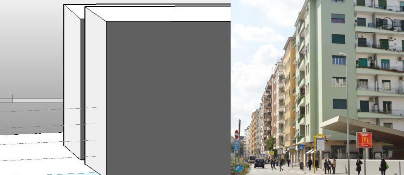
Le facciate dell'edificio analizzato sono orientate una a Nord ( la facciata con i balconi) e una a Est.
La facciata a Est risulta la più soleggiata dalla mattina presto e per tutto il prim0o pomeriggio; mentre dalle 16:00 in poi risulta in ombra.
La facciata con i balconi, esposta a Nord, risulta poco soleggiata e quasi sempre in ombra.
10. Analisi Area 2 :
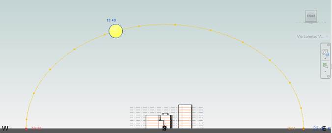
Giorno : 21 Marzo - Solstizio di primavera
ORA 13:40
ORE 15:15
ORE 18.19 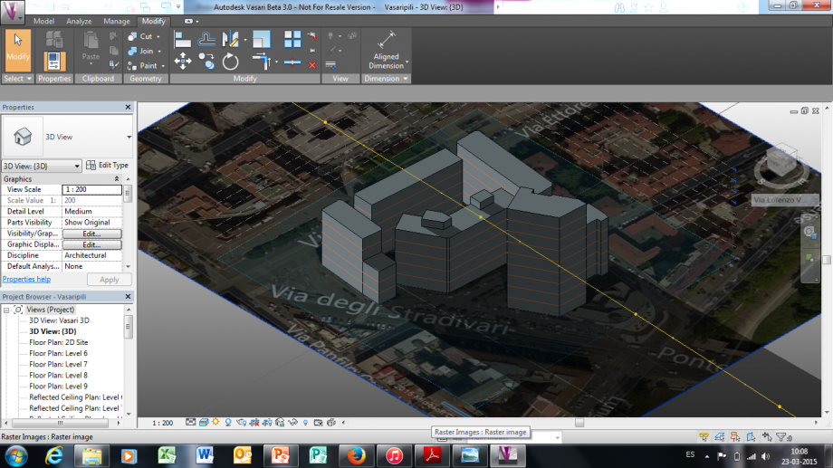
Le facciata dell'edifico analizzato, si trovano ad Est e Sud-Est ricevendo la luce solo la mattina e risultando in ombra già nel primo pomeriggio (15:15) . Non è sfruttata al massimo l'esposizione degli edifici, che inoltre ombreggiati da un edificio più alto posto di fronte.
Lun, 23/03/2015 - 22:59