 patrizio_covarelli
Lun, 23/03/2015 - 16:07
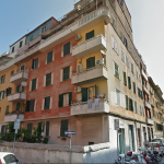
vado ad analizzare una piccola palazzina inlinea residenziale di 6 piani compreso terra situata pochi km fuori roma zona nord nel comune di fonte nuova precisamente località tor lupara zona centro
la zona non ha una massiva concentrazione di palazzine
pultroppo nei giorni che ho avuto il tempo di fare le foto pioveva e quando non pioveva era nuvoloso ...... le ombre non si notano ho un grave problema con vasari non mi accetta le password dell'autodesk
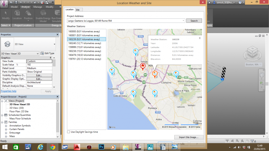
inserisco le coordinate e trovo la località mi compare il punto stazione che scelgo il piu vicino e con altidudini simili al mio edificio la mia stazione meteo scelta e' settecamini
 importo la mappa sul foglio di lavoro
 inizio a creare i solidi
  scelgo il giusto comando uso line per ricalcare le planimetria dell'edifici che circondano il mio lotto

una volta chiuso il perimetro si evidenzia e si puo' estrudere
 faccio cosi per tutti
 una volta creato il mio vicinato imposto i dati per vedere le ombre
 cosi facendo controllo tutti gli affacci del mio edeficio nei momenti critici dell'anno cioe' il sostizio destate e d'inverno e l'equinoziodi primavera e autunno

analisi dell'edificio
come si nota la parte critica e la facciata nord che maggior parte dell'anno sta completamente in ombra
l'edificio essendo il piu' alto della zona non viene sovrastato da altre ombre e avendo la facciata a sud libera e' sempre soleggiata come le facciata est
le altre due facciate non tanto l'ovest ma la nord viene soleggiata giusto nei mesi caldi completamente dopo le 15 nei mesi estivi
l'inverno e' completamente in ombra
adesso copariamo il mese di marzo cio l'equinozio di primavera (peccato che pioveva)


questa comparata e la facciata sud e est
adesso faccio notare le osservazioni fatte prima verbalmente ora tramite il programma visivamente della facciata nord
equinozio di primavera e d'autunno si nota che sia la mattina che il pommeriggio la facciata sta in ombra


ore 9:00 ombra 0re 15:00
con il solstizio estivo prendiamo in esempio oltre alle ore 9:00 e 15:00 anche il mezoggiorno con cui si nota che ancora a mezzogiorno non e' arrivato a soleggire la facciata


ore 9:00 ore 12:00

ore 15:00
il solstizio d'inverno si intuisce subito che e'una facciata che soffre per tutto il clima dell'edificio dato che sta in ombra tutto il giorno


ore 9:00 ore 15:00
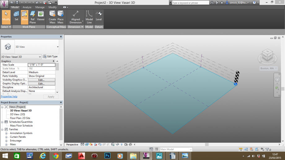
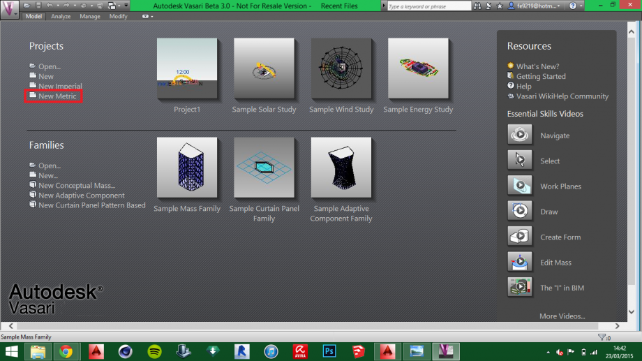
Lun, 23/03/2015 - 16:46Aprire Vasari e selezionare nuovo progetto
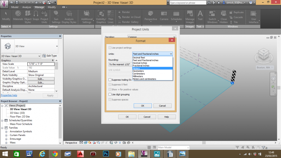
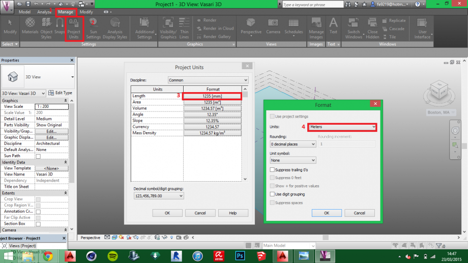
Cambiarel'unità di misura in metri
Specificare la localizzazione del progetto e la stazione meteo relativa, dunque importare l'immagine
Selezionare la zona d'interesse tramite maps

Importare l'immagine della localizzazione su livello 1

Estrudere gli edifici direttamente dall'immagine

Attivare il modello solare relativo al sito di progetto per poter analizzare il soleggiamento sugli edifici in questione

Selezionare l'ora e il giorno dell'anno in cui è stata scattata la foto dell'edificio

Attivare le ombre e comparare le viste prospettiche con le viste reali della foto

 Cori_Santucci
Dom, 29/03/2015 - 22:44
L’area presa in esame è situata in Via Virgilio Melandri, in zona Colli Aniene.
In particolare andremo ad analizzare il comportamento delle ombre degli edifici in diverse ore del giorno e diversi periodi dell’anno.
PROCEDIMENTO:
- In primo luogo, bisogna aprire un nuovo progetto cliccando su “New”
- Si impostano quindi le unità di misura nel sistema metrico decimale, cliccando su MANAGE > Project Units


- Individuiamo l’area di studio attraverso ANALYZE > Location ed importiamo l'immagine del lotto cliccando sul tasto "Import Site Image"


- Si ricava il modello 3D dalla planimetria ricalcando tramite il comando MODEL > Create Mass. Una volta finito il disegno del perimetro, si clicca su “Finish Mass”


- Finito il disegno del complesso residenziale, si procede con lo studio delle ombre con il comando in basso a sinistra “Sun Path” > Sun Setting > ON e si imposta data e ora della giornata desiderata.

- Con il tasto “Shadows on” si attivano le ombre.

ANALISI:
Abbiamo preso in esame l’ombreggiamento nei giorni di Equinozio, Solstizio Estivo ed Invernale alle ore 09:00, 12:00 e 18:00, fatta eccezione per il solstizio invernale in cui le ore prese in esame sono le 09:00, 12:00 e 16:30.
Solstizio d'Estate ore 09:00

ore 12:00

ore 18:00

Solstizio d'inverno ore 09:00

ore 12:00

Ore 16:00

Equinozio ore 09:00

Ore 12:00

Ore 18:00

La zona presa in esame è denotata dalla presenza di 5 palazzi in linea con orientamento Nord/Sud, distanziati tra loro da ampie aree pubbliche (giardini, zone pedonali, strada) e delimitati ad ovest da un edificio piuttosto imponete di 11 piani che presenta nel piano terra e nel primo piano attività commerciali.
In particolare abbiamo voluto prendere in esame l’edificio più vicino a quest’ultimo.
Dalle immagini si deduce che durante il periodo estivo l’edificio e le aree verdi circostanti, presentano soleggiamento intenso dalla mattina sino al primo pomeriggio, durante appunto le ore più calde della giornata. La presenza però di questo verde riesce a mediare in parte il calore che tale irraggiamento provoca.
Invece nel periodo invernale, l’area risulta ampiamente ombreggiata nelle prime ore della mattina e nel pomeriggio comportando un uso limitato delle aree verdi da parte degli abitanti alle sole ore centrali della giornata. Sebbene il palazzo più esposto verso ovest comporti dei vantaggi da un punto di vista acustico di questa zona più residenziale, d'altro canto però questo proietta un'ombra eccessiva andando ad inficiare negativamente sull'esposizione dei palazzi circostanti.
Infine abbiamo comparato le ombre della facciata esposta a Nord in un giorno particolare a determinate ore del giorno, paragonando i risultati fotografici con quelli del modello.
Giorno 23/03/2015 ore 09:00


Ore 12:00


Ore 16:30


Dalle analisi precedentemente fatte possiamo dedurre che l’edificio in questione, se da un lato ha il vantaggio di essere protetto dall’inquinamento acustico di via Palmiro Togliatti, è abbastanza penalizzato duranti le fasi pomeridiane della giornata dall’edificio di 11 piani adiacente. Infatti dalle foto delle 16.30, possiamo notare come l’ombra di questo vada a coprire il prospetto nord/ovest/sud oltre che la strada antistante ed i giardini. Ciò comporta all’interno dell’edificio una mancanza di irraggiamento diretto nei salotti e nelle camere da letto, posti appunto nel lato del prospetto nord. Al contrario durante le ore del mattino non mostra nessun problema particolare, presentando il fronte sud ampiamente soleggiato nella prima parte della giornata ed il prospetto nord in ombra.
Per quanto riguarda le aree pubbliche, in particolare i giardini che si trovano a nord ed a sud del palazzo, possiamo notare che hanno un ampio soleggiamento dalle ore 9.00 fino alla fine della mattinata, per poi rimanere in ombra durante tutto il pomeriggio.
Lun, 23/03/2015 - 15:52 Marco_Feola
Lun, 23/03/2015 - 15:33
This performance is due in order to analyze the shading of a residential building located in Rome, Via Galvani 37, Rione Testaccio.
The purpose of the exercise is to illustrate the basic commands have been used.
> Opening of Vasari Beta 3 > insert "new metric" as reference scale
In order to change the IUF measured in linear meters, follow the subsequent instructions:
1) > "Manage"
2) > "Project units"
3) > "Length" and set
4) > "Units": in "Meters". Finally press OK
5) > "Analyze"
6) > "Location"
A window will be opened that will ask you to enter the address of the area in question. Once you have found the area, we will import the image of the place.
> "Import Site Imge"
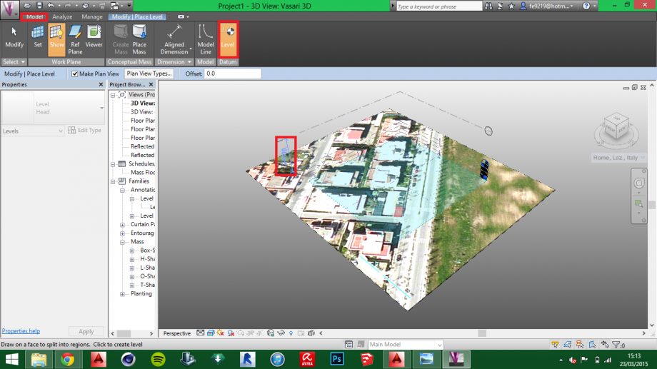
(Internet connection is needed for the following steps)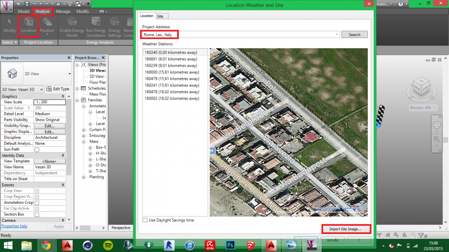 To set a new level:
> "Model"
> "Level"
Within the model you'll see a vertical dimension corresponding to the height of the level you are going to accomplish.
(Vasari default sets three levels of 3 linear meters eachone)
 To realize the perimeter of the buildings do:
> "Model"
> "Create Mass"
Inside of > "Modify / Form" will open a curtain, you will choose the type of command based on the shape of the buildings that you're going to trace.
Once traced the building clicking inside it with the left mouse button, you will open a vertical vector with which you can indicate the height.
To conclude these proceedings click > "Finish Mass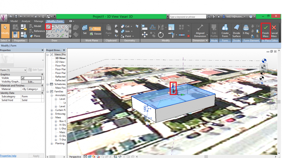 To enter the solar trend within the model, click the icon > "Setting Sun" that will give you the chance to enter the location, date and time of the place being studied
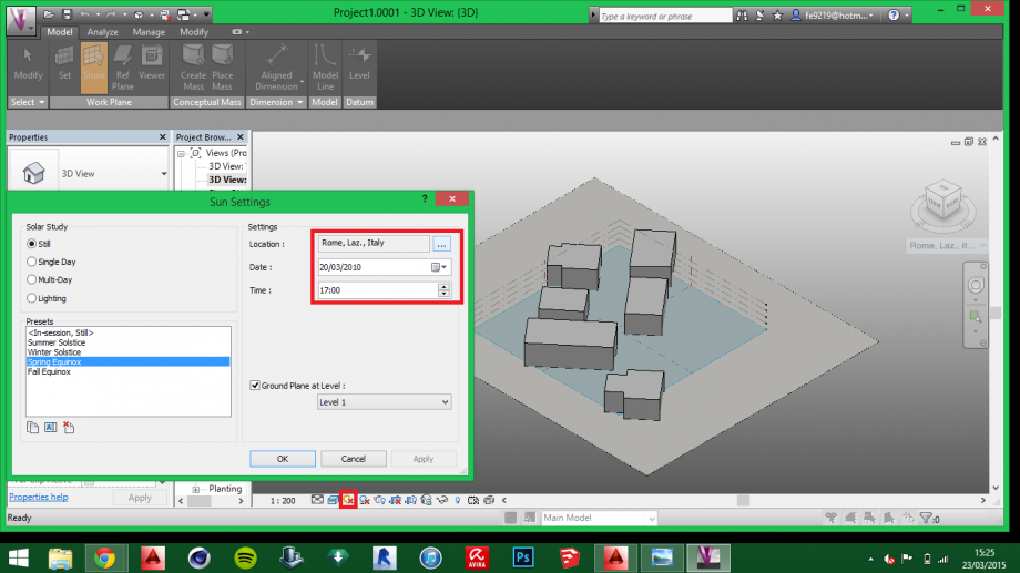
After entering the solar trend we can analyze how the building behaves at different times of the day.
The area that we have analyzed is located in a housing development primarily composed of residential buildings no taller than four floors.
We'll analyze the behavior of the building during the day, through an analysis of the shadows.
General overview
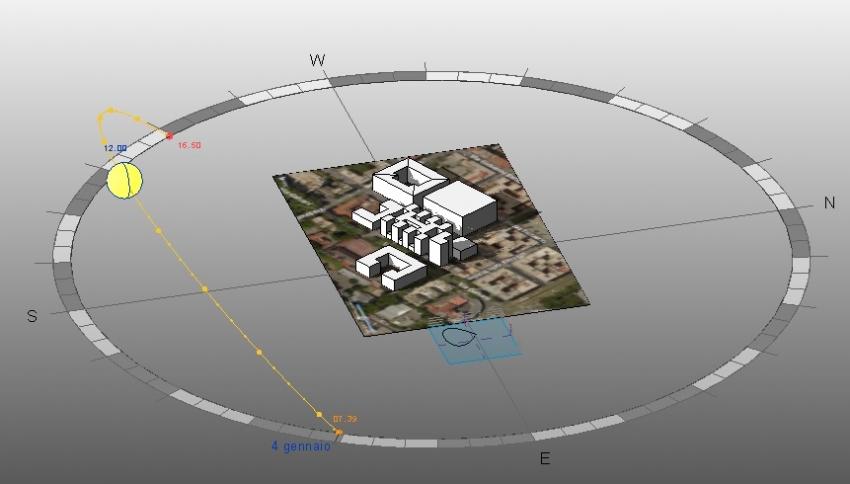
Solar path 29/03
West side
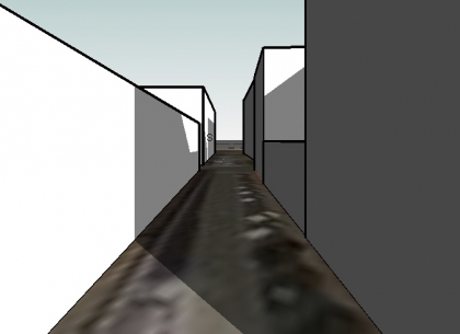
8:30 of 29/03
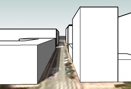
12:40 of 29/03
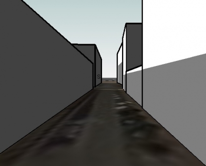
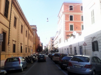 16:40 of 29/03
North side
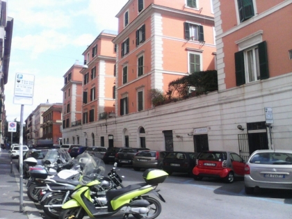 13:20 of 29/03
 15:30 of 29/03


