


 Giacomo_Cavalieri
Lun, 23/03/2015 - 17:43
Giacomo_Cavalieri
Lun, 23/03/2015 - 17:43
Analisi Edificio Via Federico Nansen tramite Vasari
Procedimento:
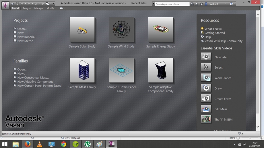
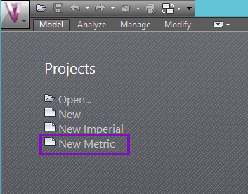
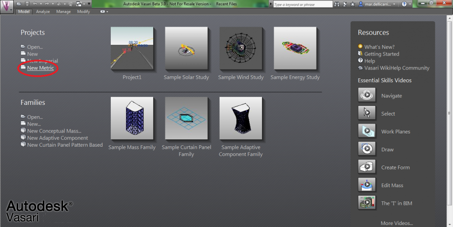
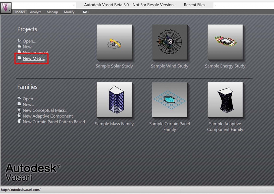
1. Apro il programma vasari e inserisco l'unità di misura adeguata (seleziono New Metric);
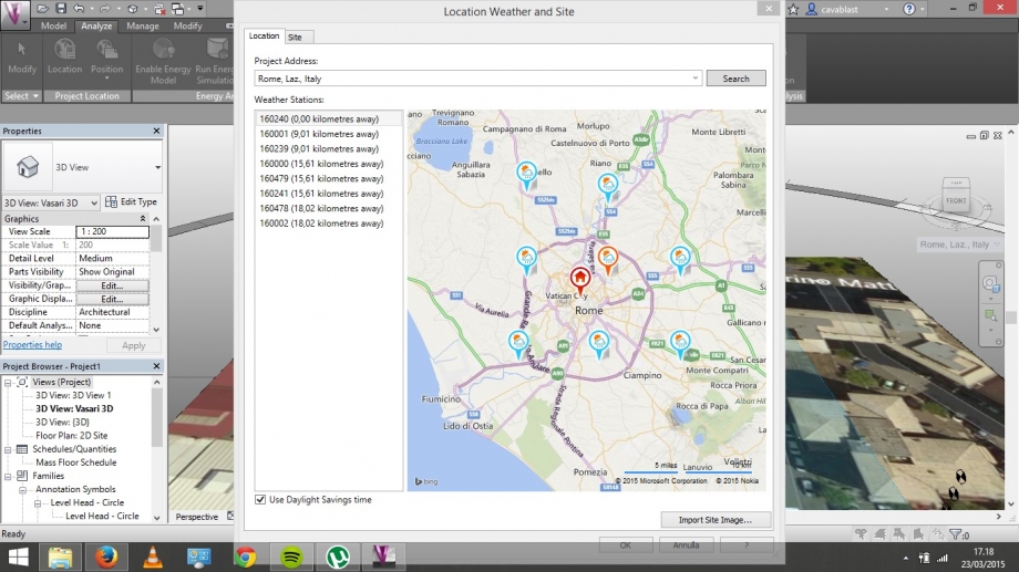
2. Localizzo la mia area di analisi (Analyze > Location > Rome,Laz., Italy) metto un check al riquadro "Use Daylight savings time" e importo l'immagine dal sito;
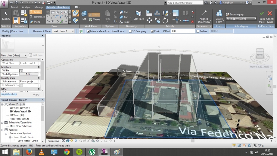
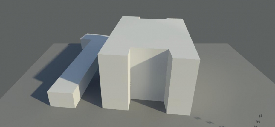
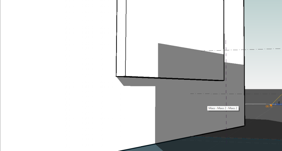
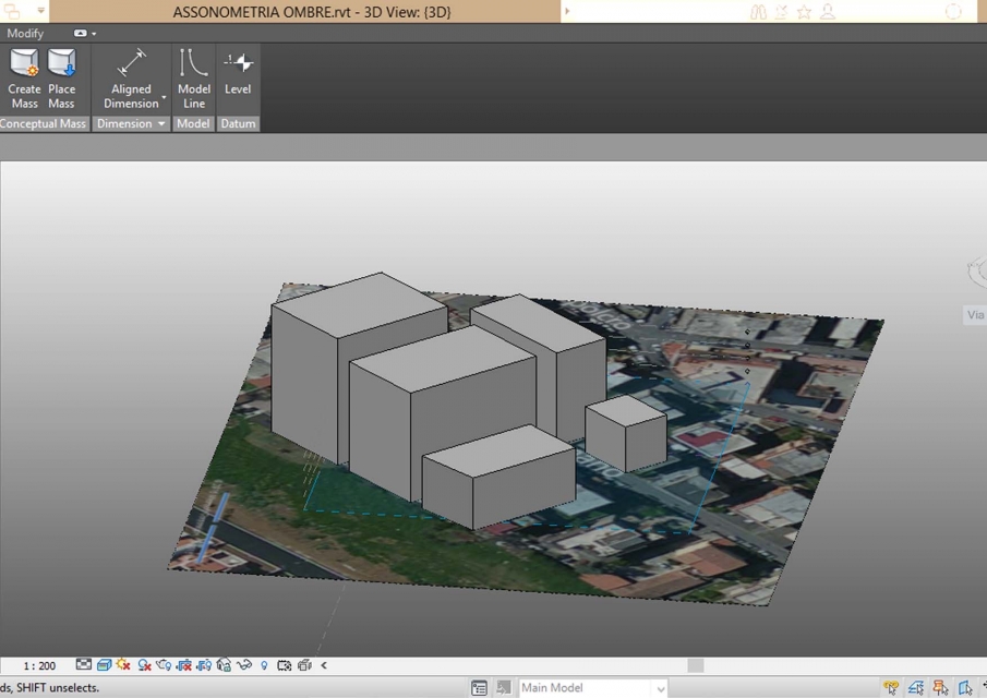
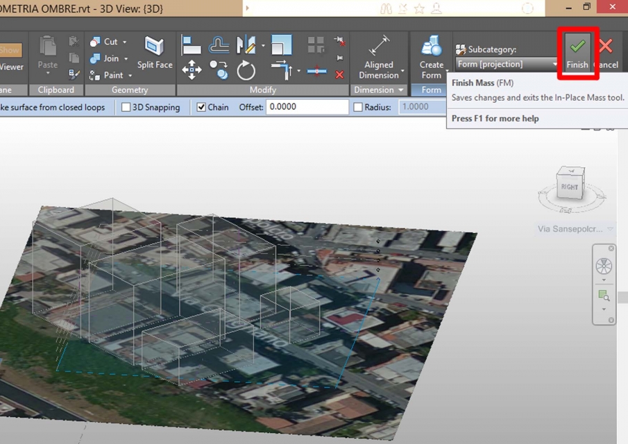
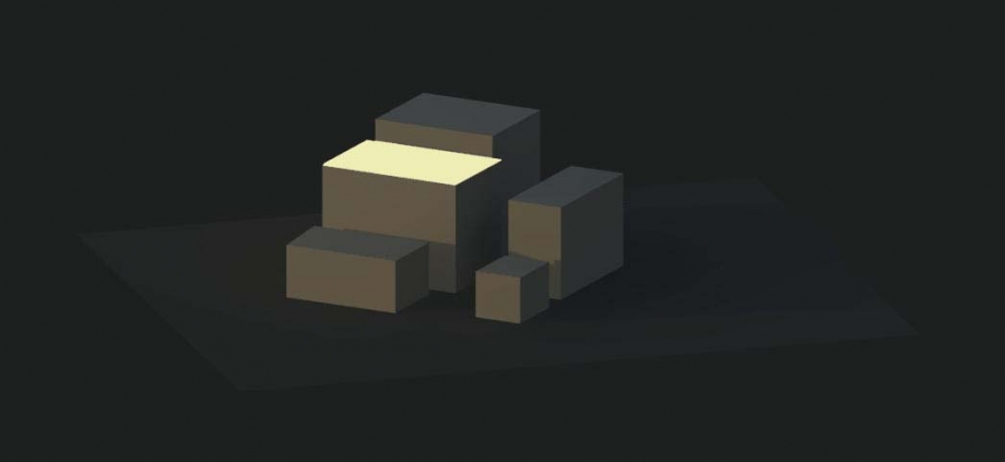
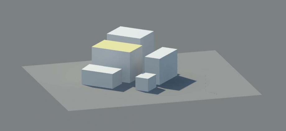
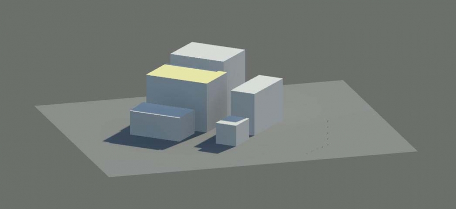
3. Creo l'edificio (Model > Create mass > Draw line > Create Form > Finish Mass);
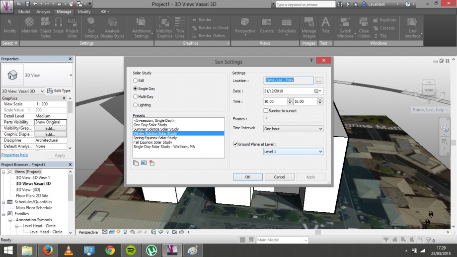
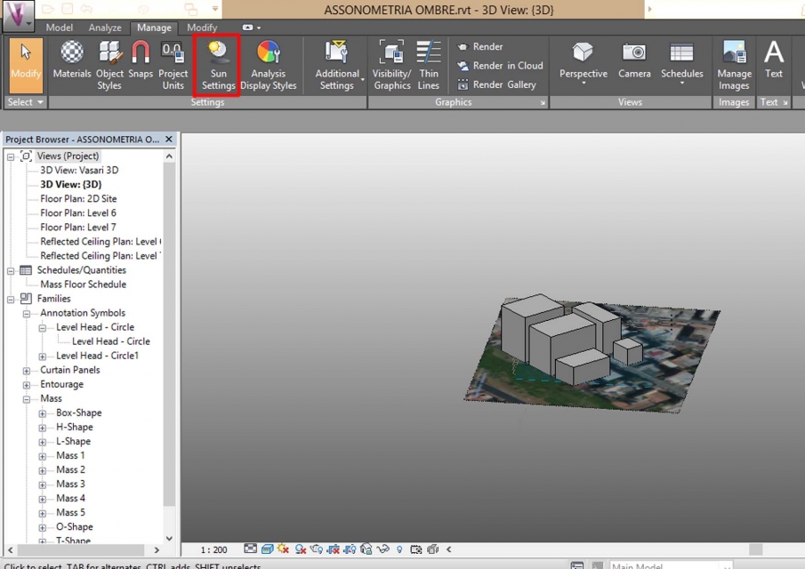
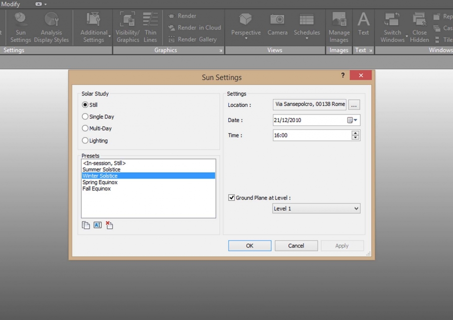
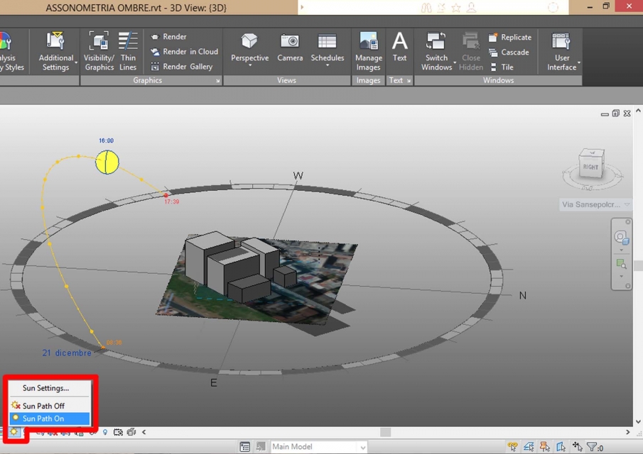
4. Attivo "Sun Path" e "Shadow" e tramite "Sun Settings" imposto gli orari e le dadte d'interesse;
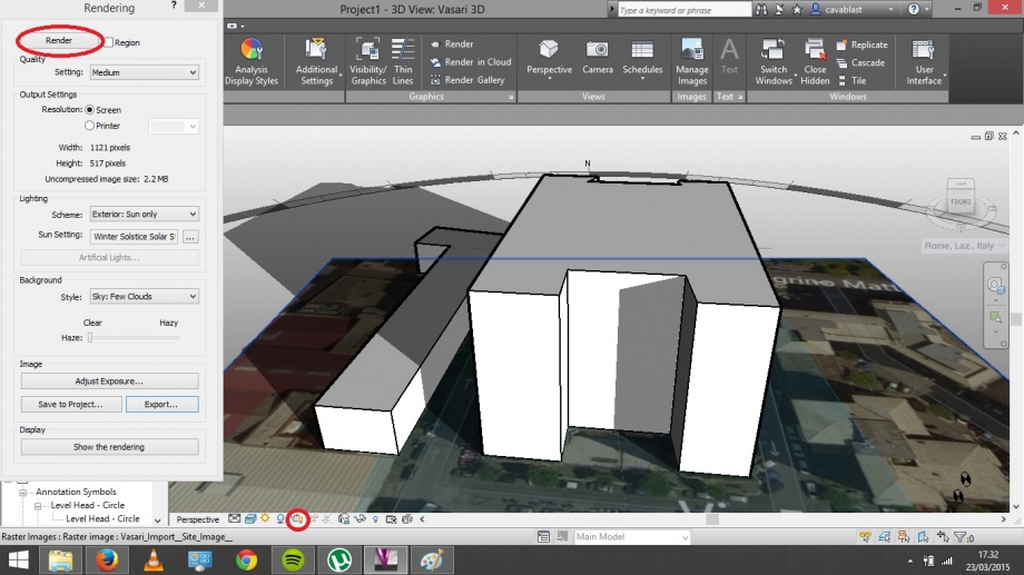
5. Una volta selezionata la data d'interesse creo dei Render tramite l'icona "teiera" localizzata al di sotto dell'immagine e seleziono il comando "Render";
Fine.
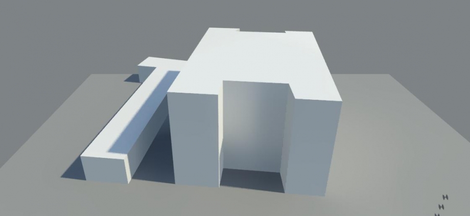
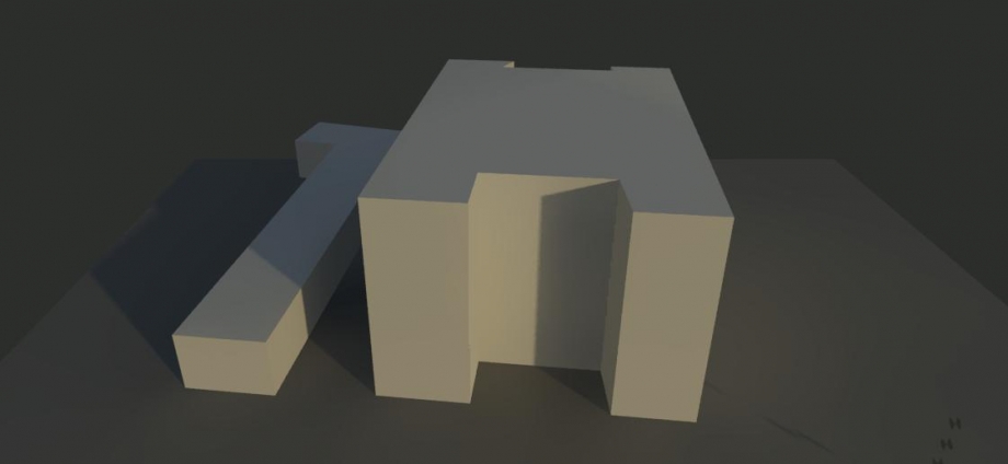
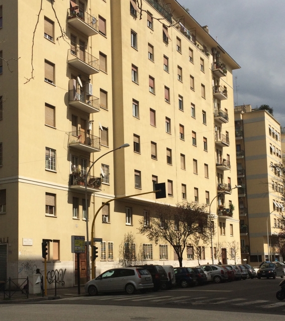
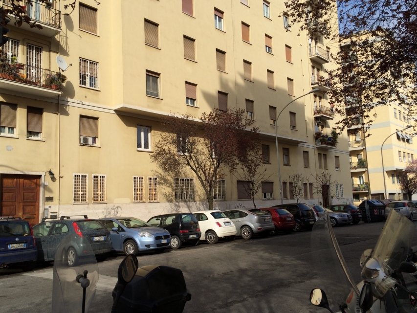
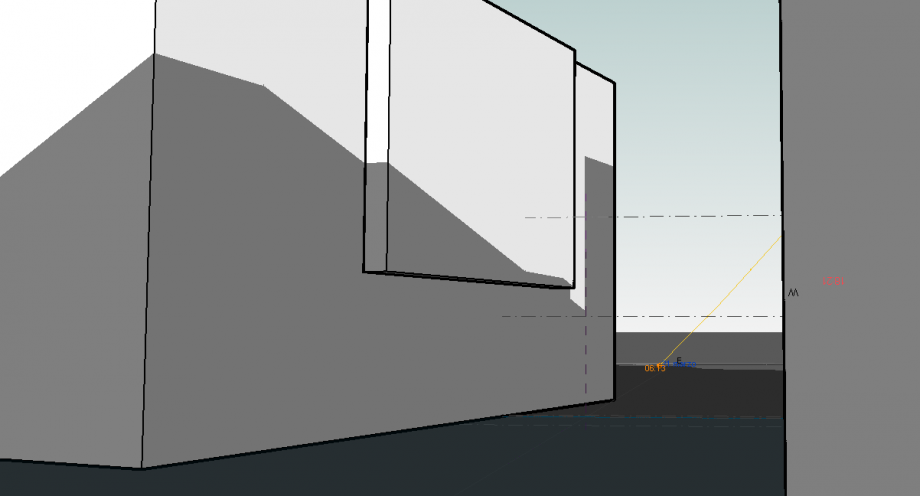
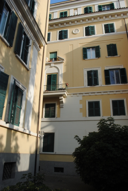
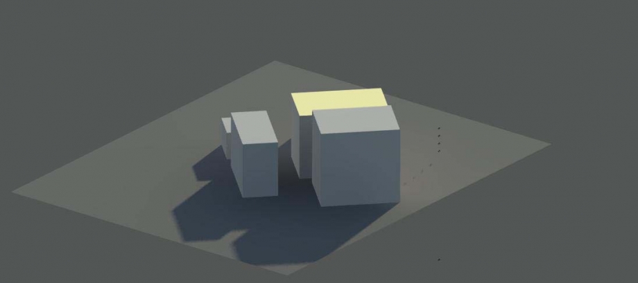
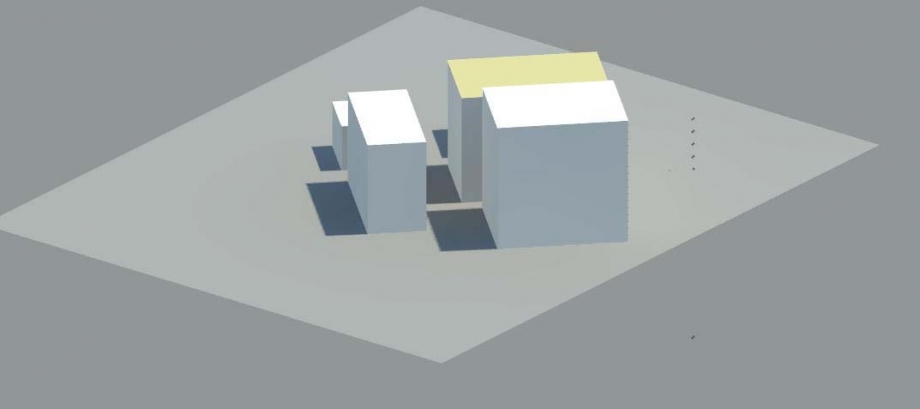
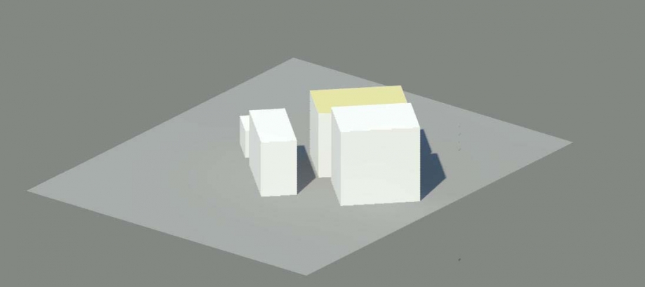
In particolare ho analizzato l'ombra che l'edificio di via nansen proietta sul palazzo di minore altezza posizionato davanti ad esso
Solstizio d'estate:
Solstizio d'inverno:
Equinozio di primavera:
 Folgiero_Guratti
Lun, 23/03/2015 - 16:28
Folgiero_Guratti
Lun, 23/03/2015 - 16:28
STEP 1: Start a new project and localize it.
Open VASARI and select NEW METRIC to start the project.
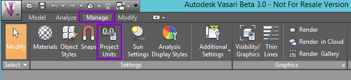
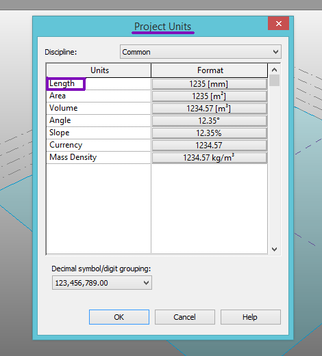
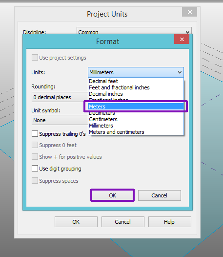
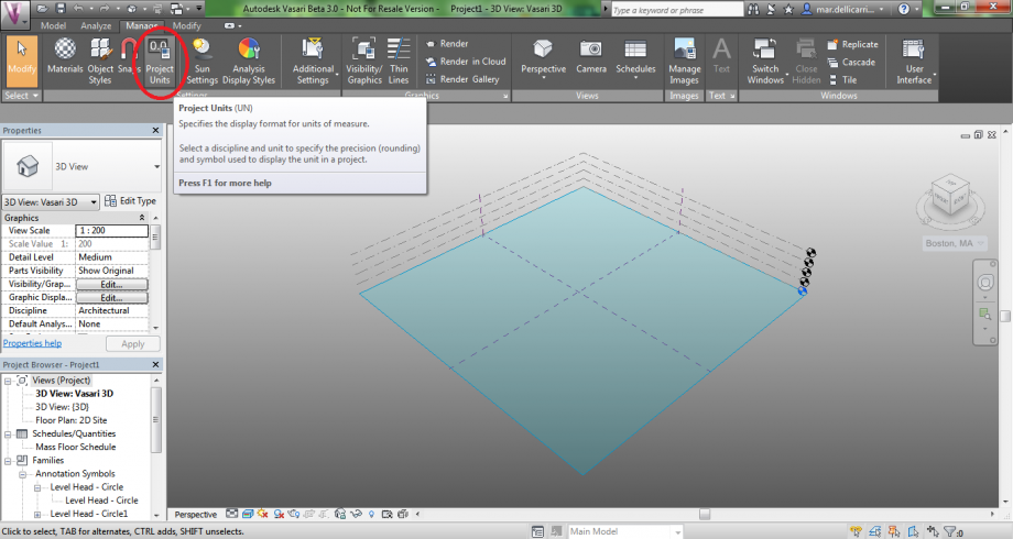
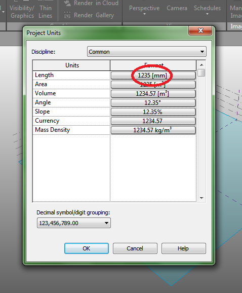
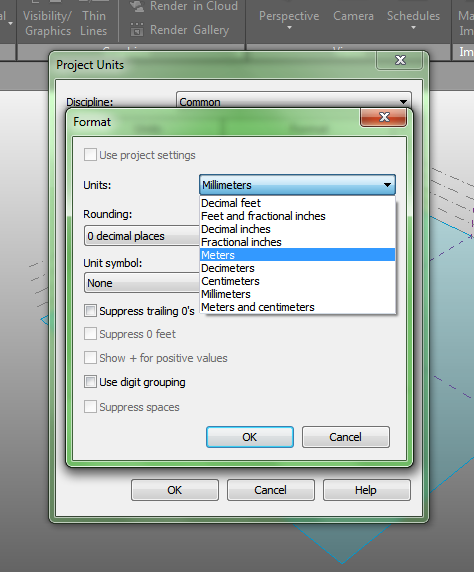
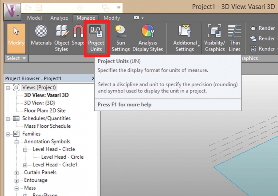
Select MANAGE > PROJECT UNITS: here it’s possible to change the units of measure of length from millimeters to meters.
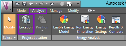
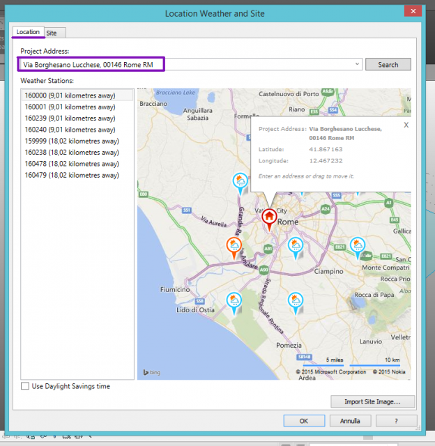
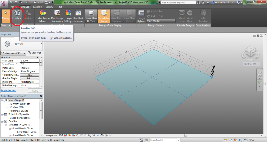
Click on ANALYZE > LOCATION to specify the geographic location of the project. Vasari uses in fact an Internet mapping service to visualize the project location by searching on its street address, or the longitude and latitude of the project.
Finally, IMPORT SITE IMAGE on the level one.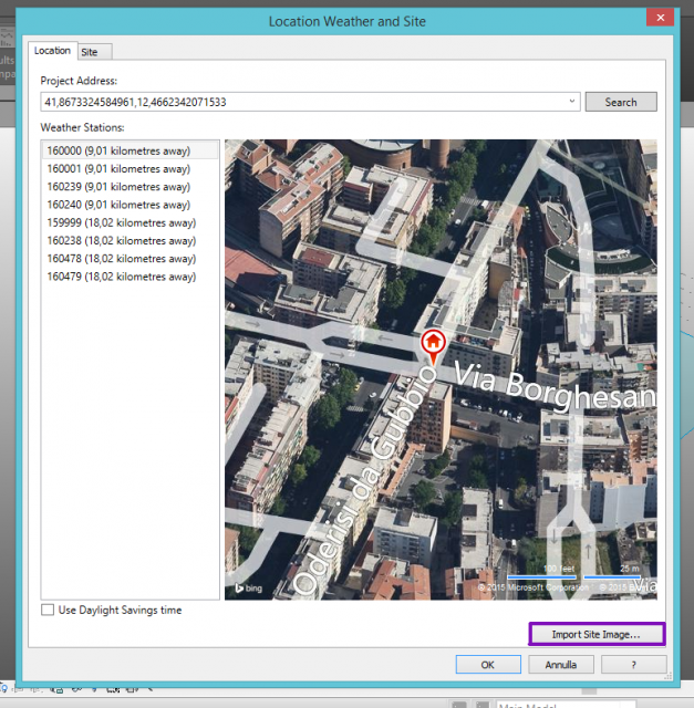
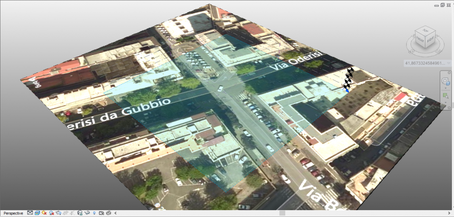
Site image imported:
STEP 2: Drawing the buildings
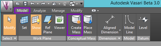
After importing the image of the project’s site, click on MODEL > CREATE MASS
and select MODEL LINE > DRAW ON WORK PLANE to draw lines on the actual work plane.
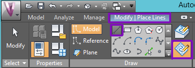
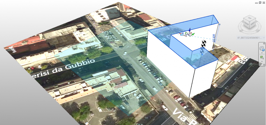
Now it’s possible to draw precisely the plan of the building directly from the site. To extrude the volume, click on MODIFY | PLACE LINES > CREATE FORM > SOLID FORM,
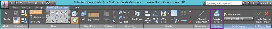
and then set the height of the building:
STEP 3: Sun path study
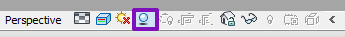
It’s possible to access the sun and shadows settings in the lower panel of Vasari: by clicking on SUN PATH ON you will activate a sun model which can be moved around the path of the sun based on your geolocation.
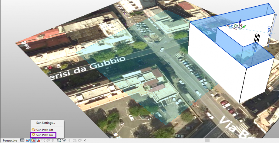
Clicking on SHADOWS ON it’s also possible to activate shadows and see when the model is shaded or shades the sunroundings.
This is the final effect:
STEP 4: Our study
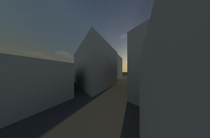
For this exercise, we decided to analyse two buildings at the intersection of Via Oderisi da Gubbio and Via Borghesano Lucchese, since they have a big, free an simple facade on which we can easily study the sun behaviour.
In SUN SETTINGS, we analysed the most significant moments of the year, since the day of study that we chose is the 21st March, the spring equinox.
WINTER SOLSTICE, 21st December
 h. 8,30 - 21/12
 h. 12,00 - 21/12
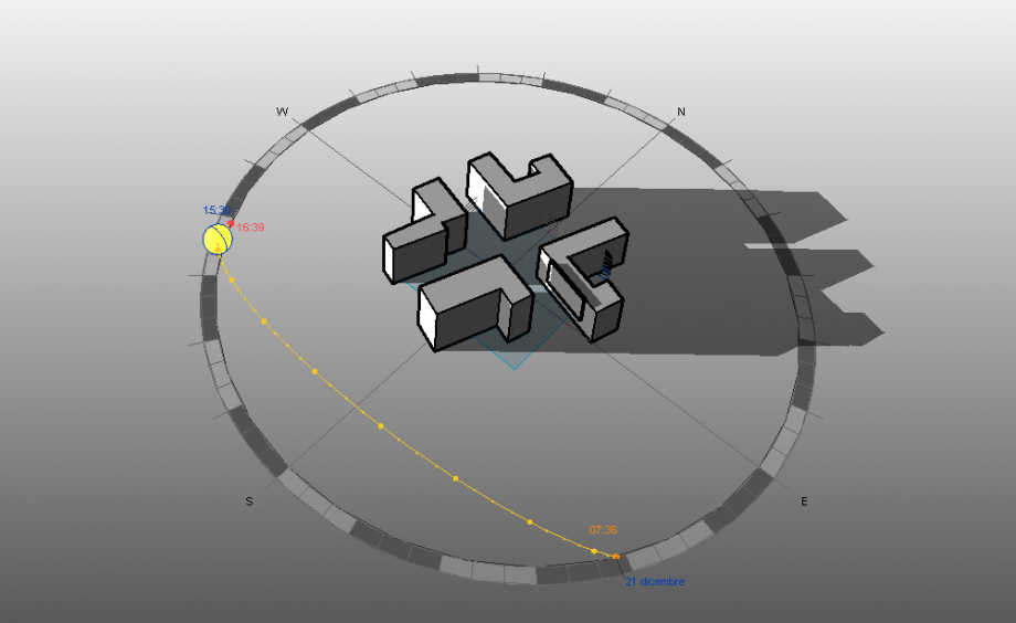 h.15,30 - 21/12
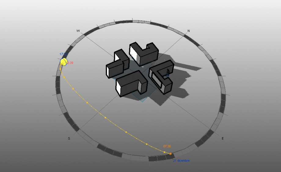 h.17,00 - 21/12
The sun path is lower, so we can observe that the North facades of both buildings never receive direct sunlight. Also, the two buildings receive direct sunlight almost only in the first part of the day.
SUMMER SOLSTICE, 21st June
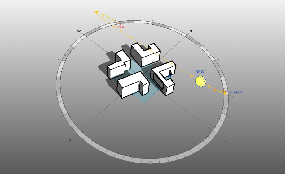 h. 8,30 - 21/6
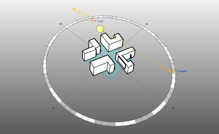 h. 12,00 - 21/6
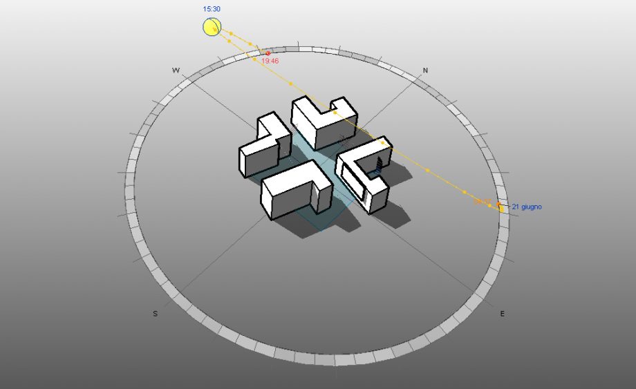 h. 15,30 - 21/6
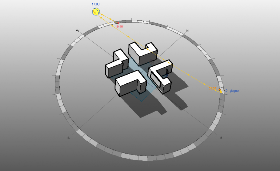 h.17,00 - 21/6
The sun path is higher so, during the central hours of the day, almost the whole building receives direct sunlight, in both cases.
AUTUMN EQUINOX, 22nd September
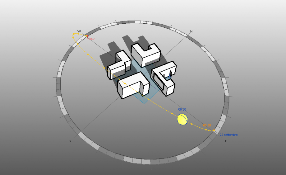 h. 8,30 - 22/9
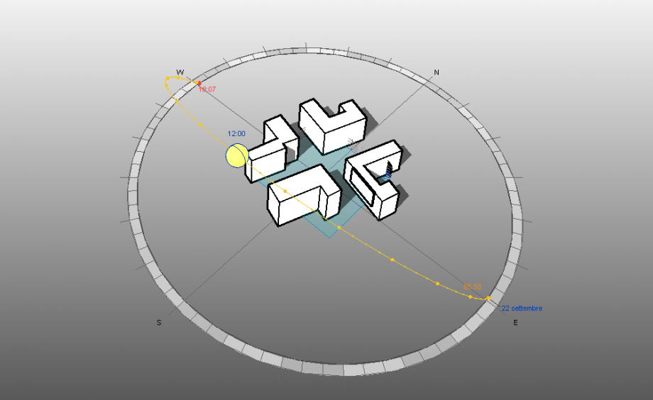 h.12,00 - 22/9
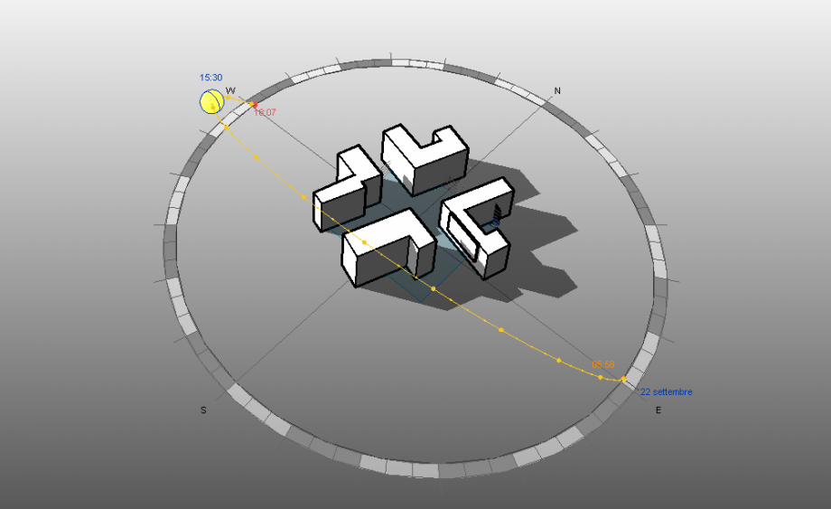 h. 15,30 - 22/9
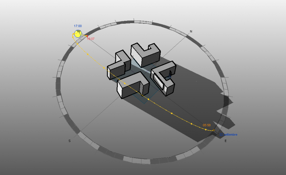 h. 17,00 - 22/9
Here the sun path is very similar to the day we analyzed, the 21st March, the Spring Equinox.
SPRING EQUINOX, 21st March
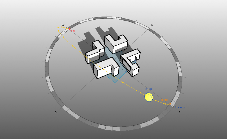 h. 8,30 - 21/3
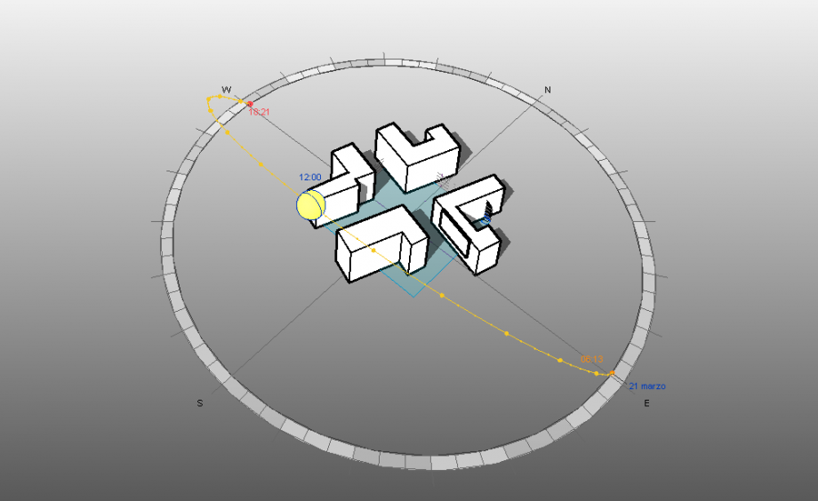 h. 12,00 - 21/3
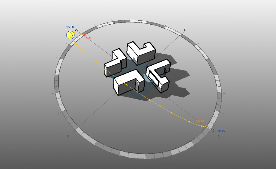 h.15,30 21/3
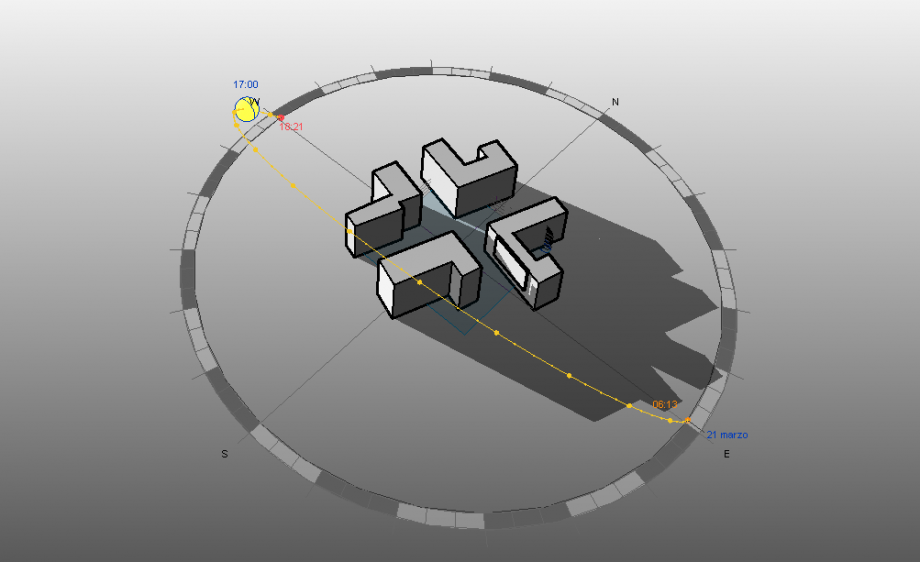 h. 17,00 - 21/3
We’ve picked the date (21 March) and the different times of the analysis (08:30, 12:00, 15:30, 17:00) in order to compare the shadows in different moments of the day.
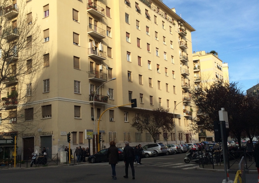
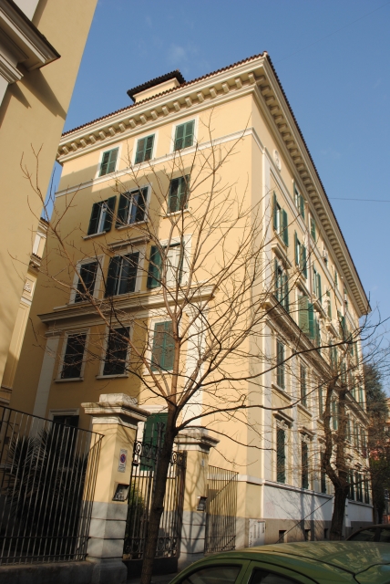
Our study is focused on two buildings on Via Borghesano Lucchese, both of eight floors.
The building on the right, during our day of study, never received direct sunlight on the facade, in fact it is exposed to North.
The East facade of both buildings receives direct sun only during the first few hours of the day (from 8.30 to 12.00). This could be a problem especially for the building on the right side, while on the other side, the South facade of the other building receives obviously more direct sunlight, mostly in the first hours of the day, beetween 8:30 and 15:00, but actually during all day.
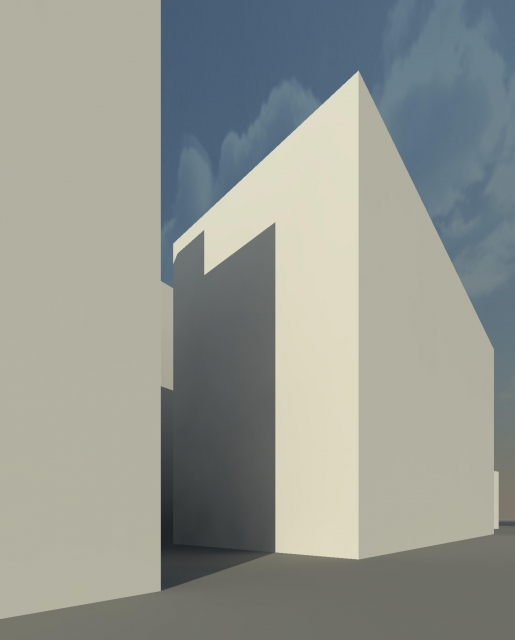
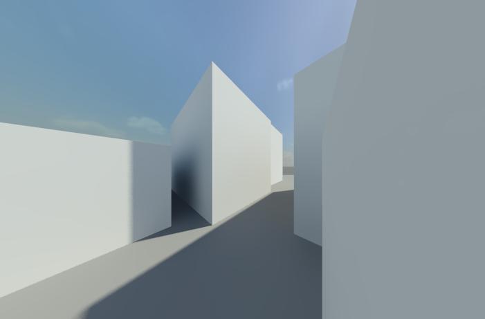
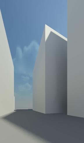
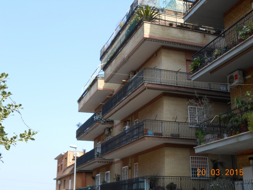
Then we compared the render perspective views, obtained with the FULL NAVIGATION WHEEL tool, with the photographic surveys taken on the selected date, in order to verify the actual correspondence:
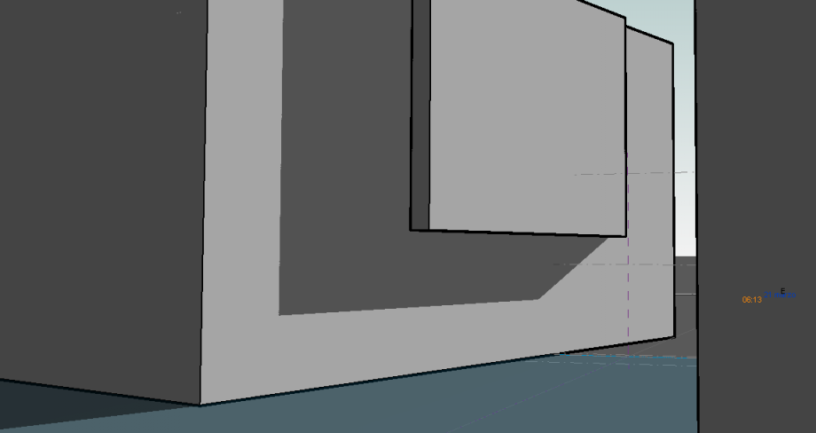 Full navigation wheel from Via Borghesano Lucchese at 8,30.
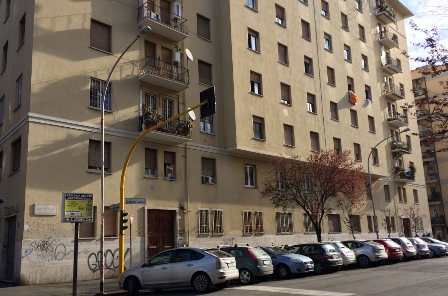
perspective view from Via Borghesano Lucchese at 8,30.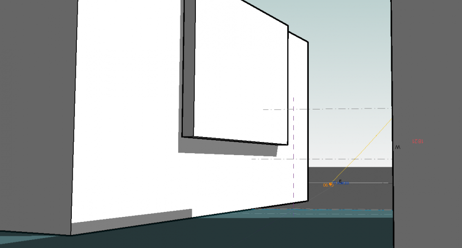 Full navigatuon wheel from Via Borghesano Lucchese at 12,00.
perspective view from Via Borghesano Lucchese at 12,00.
Full navigation wheel from Via Borghesano Lucchese at 15,30.
perspective view from Via Borghesano Lucchese at 15,30
 Full navigation wheel from Via Borghesano Lucchese at 17,00.
 perspective view from Via Borghesano Lucchese at 17,00
Lun, 23/03/2015 - 17:36
 Delli Carri_Luongo
Lun, 23/03/2015 - 16:39
Delli Carri_Luongo
Lun, 23/03/2015 - 16:39
1. SET YOUR WORKING PLANE
Open Autodesk Vasari and select New Metric on the left upper side of the home page.
This way you will open the following screen, with an empty plane.
2. SET PROJECT UNITS
Select Manage>Project Units in the upper bar and set ‘meters’ as length unit.
3. SET LOCATION
To set your location, select Analyze>Location from the upper bar.
! In order to choose a location, you are required to sign in with an Autodesk account. If you do not have one, sign up!
Search for your Project Address and then select a Weather Station, among the ones shown on the map. Check Use Daylight Savings Time (which I haven’t done), then click Import Site Image>Import.
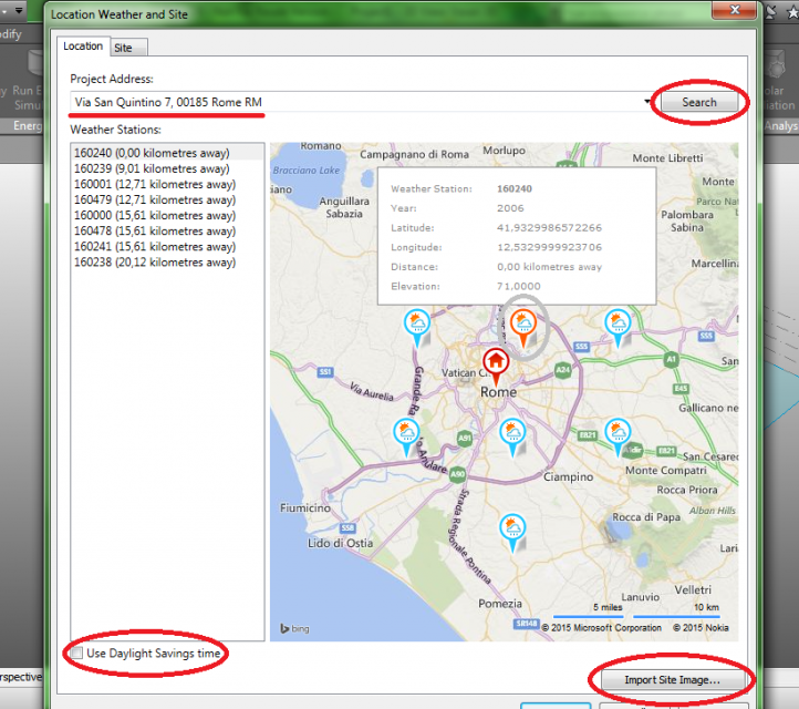
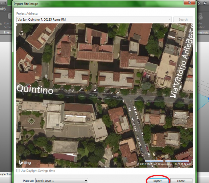
A map of your location will now be shown on the plane.
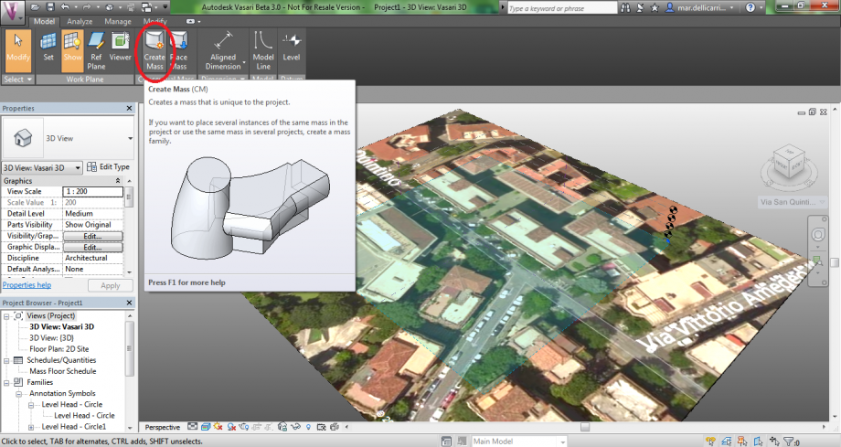
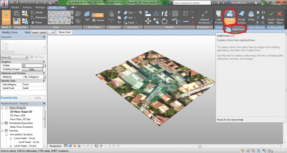
4. EXTRUDE BUILDINGS
Now that your ground plane is set, you will have to extrude the buildings on the map, in order to set the shadows. Select Model>Create Mass.
Select the shape of your building’s base. In this case, a rectangle.
To make it easier, set the Top view on the upper right side of the page, then draw your shape.
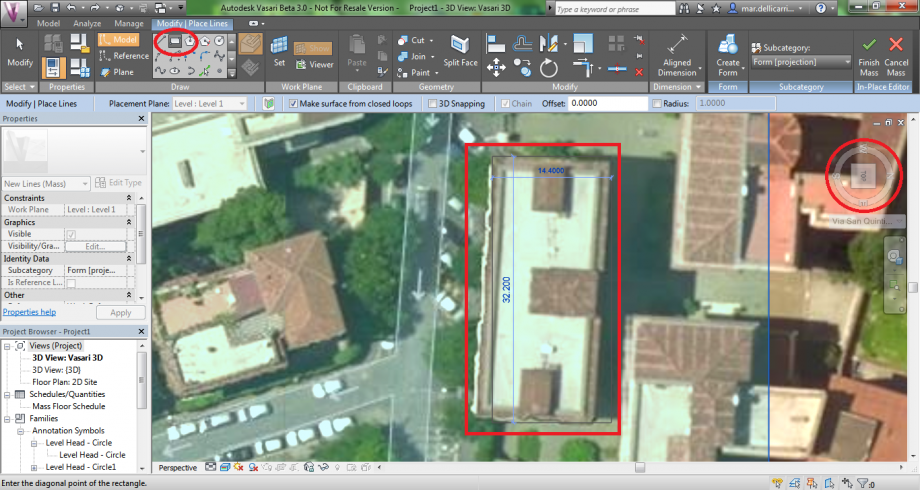
(Your rectangle might not be aligned with the map, but you can rotate it afterwards).
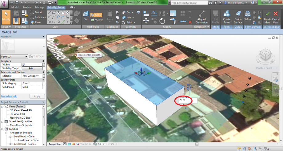
Now select your shape and click Create Form>Solid Form.
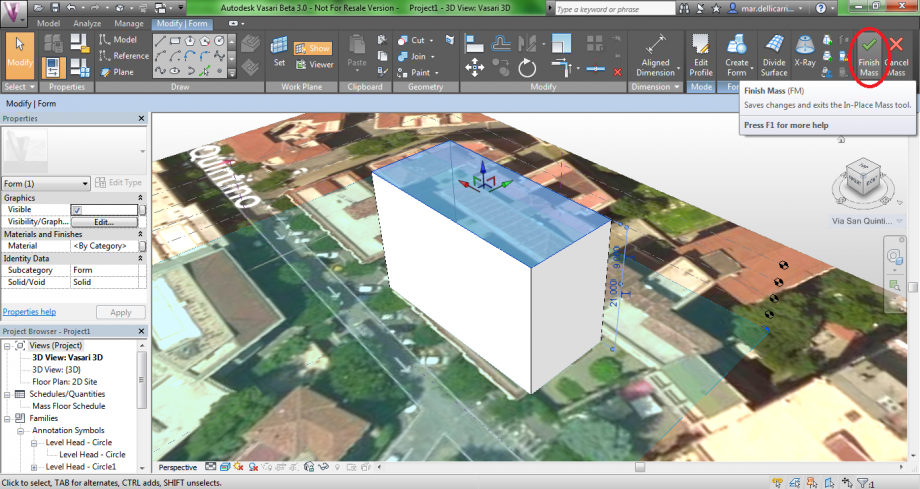
You can change the building’s hight by clicking the vertical dimension. Remember to write ‘m’ (meters) after the new dimension!
Then click Finish Mass.
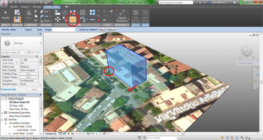
5. ROTATE
Select Modify|Mass>Rotate, place the Center of Rotation moving the blue dot. Then select the corner you want to move and replace it.
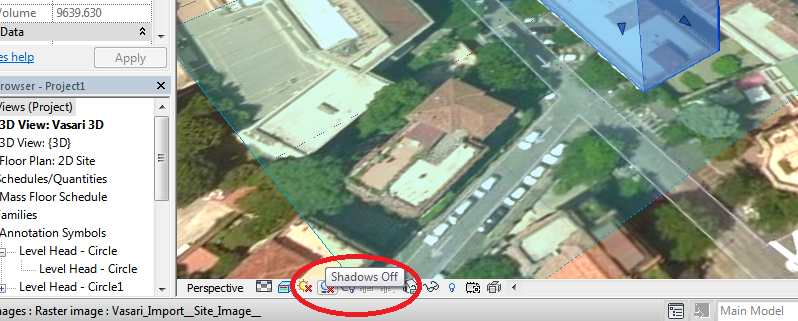
6. SHADOWS AND SUN PATH
Let’s now consider the lower bar. You will see there is a red X on two icons: activate shadows and sun path by clicking on them.
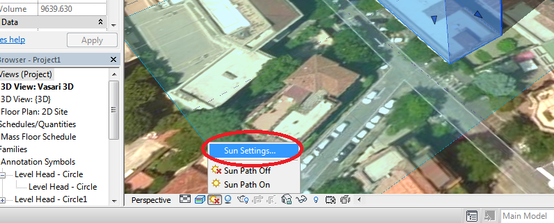
Then press Sun Settings… and set date and time.
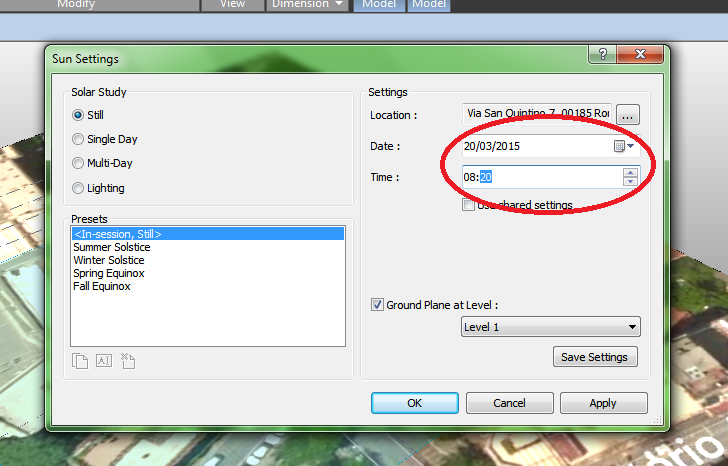
I chose to set March 20th, 8.20am.
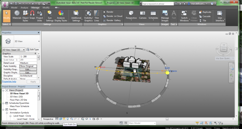
Sun path (visible by zooming out, once activated) shows the position of the sun at that certain time.
You can now place all the other buildings (following points 4 and 5 again).
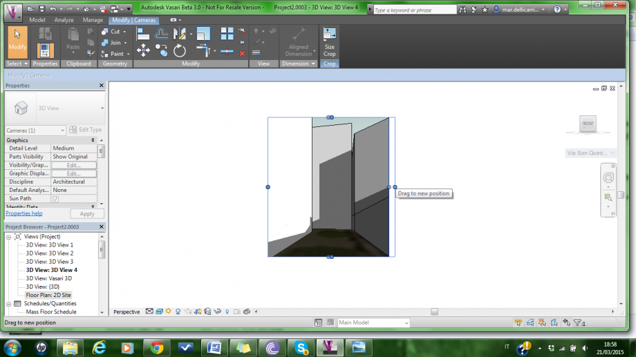
7. SET CAMERA
Select Floor Plan: 2D Site, from the left bar. Then click Camera, place the camera icon on the point of view and direct the visual cone towards the building.
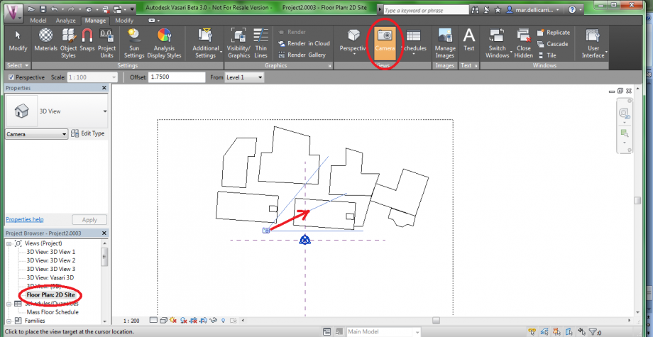
If the framing is too narrow, you can widen it by stretching the sides.
Check if sun path and shadows are still on, because they might have turned off.
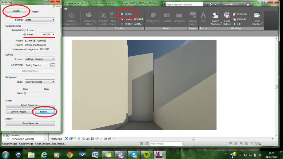
8. RENDER
Now select Manage>Render. Then click Printer resolution, and set the DPI.
Click Render, and wait for it to be done. If you like it you may press Export… and save it. Otherwise click Show the model to change settings.
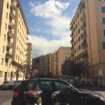
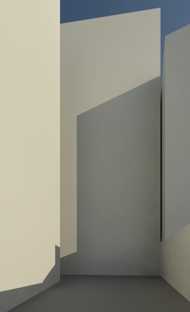
You can check your work by taking a picture of the building from the same point, on the same day and at the same time.
San Quintino st, 7 ROME. March 21st, 8.20am.
Now, a few more examples:
San Quintino st, 7. March 21st, 4.20pm.
Mazzini av, 6. March 23rd, 8.00am.
Lun, 23/03/2015 - 17:36
 grandais_stafie
Lun, 23/03/2015 - 16:51
grandais_stafie
Lun, 23/03/2015 - 16:51
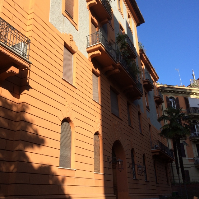
EX.1 - TESTING SHADOWS
Baptiste Grandais & Marie Stafie
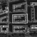
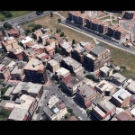
Step 1 : localization of the project
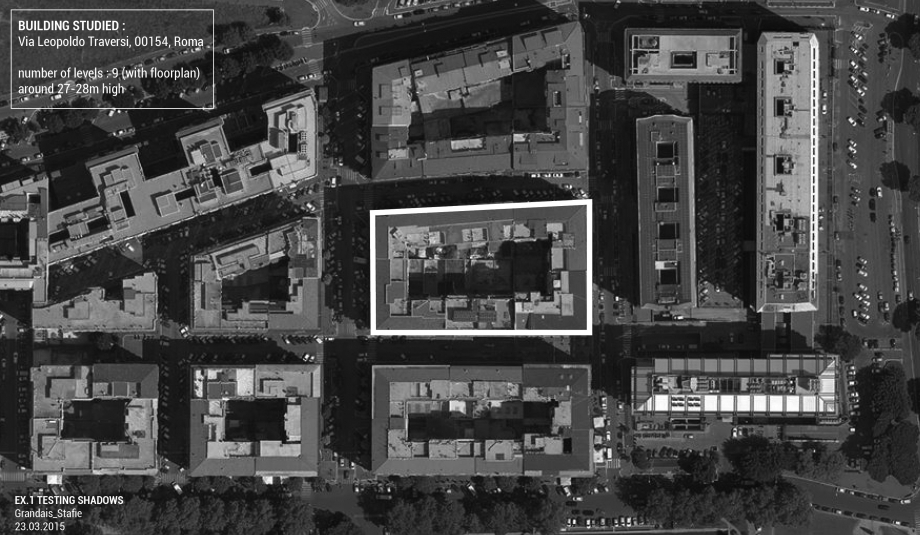
Our study is focused on the building on Via Leopoldo Traversi, with its surrounding buildings. This part of Garbatella neighborhood is characterized by very similar buildings, having generally the same number of levels ; from 9 levels (with floor level) for our building, to 10 levels for the surrounding buildings. This typology of neighborhood is very interesting to analyse because of the high number of levels and the proximity of each buildings. Analyzing the sun shadows and the direct sunlight the facades receive is a good way to find out what kind of problems these type of buildings can encounter.
Methodology:
Create the area
> set location of the building
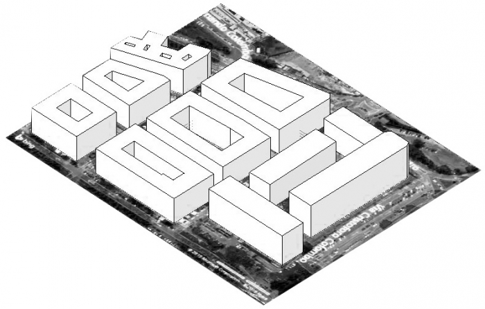
> create contours of the buildings
> extrude the volumes of these contour
> create contours of courtyards
> extrude these as voids
Shadows analysis
> enable sun path
> change sun setting of differents dates of the year
> for each dates select 3 hours of the day to look how the area interacts with the sun
Picture comparison
> set camera location
> export picture and compare with the real photography
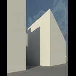
Step 2 : drawing the buildings
Step 3 : sun path study
By testing the shadows in the street façade but also in the courtyard façade, we got to understand how much direct sunlight both receive. In order to have different relevent variations, we chose to set the most significant moments of the year ; the winter solstice(22 december), the summer solstice (21 june) , the autumn equinox (23 september) and finally the spring equinox (close to the day we analyzed : 23 March) . For each significant diagram we set three different hours : 08:00, 12:00 and 16:00.
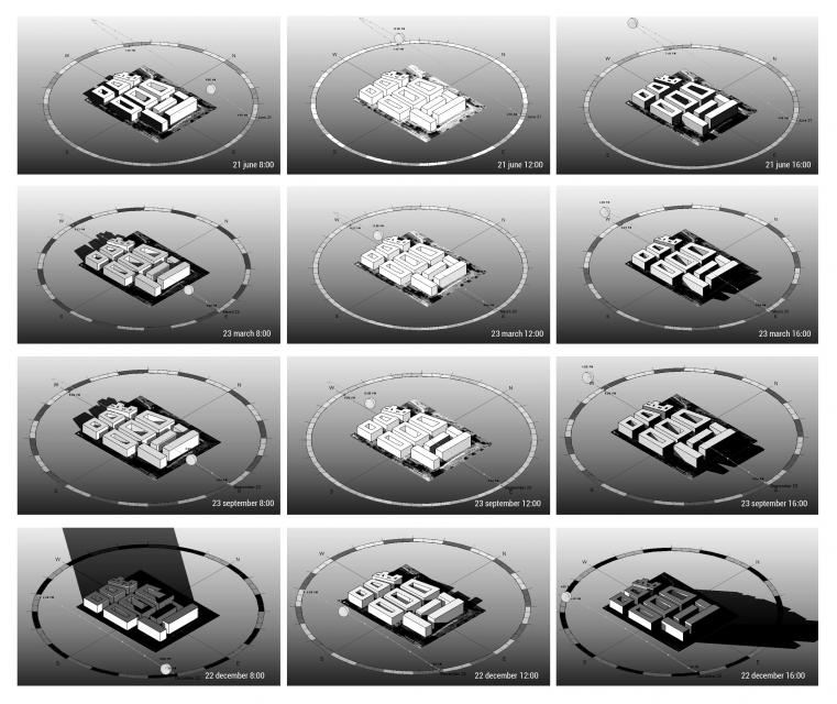
Observations :
During the winters, the major part of the appartments from the groundfloor to the last floor haven't got enough direct sunlight, all day long. Even in the summer the first and the groundfloors don't get enough direct light, we can say that the urban web is too dense to provide it for all appartments. But the courtyard typology offers an alternative solution to this problem, providing direct and indirect light with the reflexion on the facades. As for the shadows, it's obvious that during summer, they offer fresh air in the streets but the last floors of the buildings suffer from high temperatures exposition. After these observations, we can conclude that the presence of architectonical elements on the facades can also be a solution to high sunlight exposition, that we will see on the next episode. :)
Step 4 : comparison between software and photo
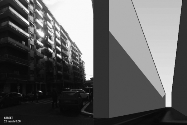
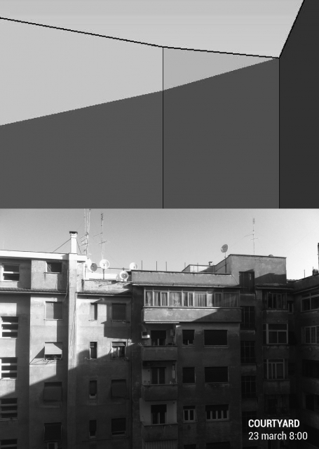
Then we compared the render perspective views extracted from Vasari software with the pictures we took, taking the same angle of vision, and date settings, in order to verify the correspondence. We observered that for the courtyard analysis, the shadow is clearly equal, as it is for the street view, but with a less clear leggebility of the shadow form, caused by the presence of various architectonical elements on the facade.
Lun, 23/03/2015 - 17:26
 Mariucci_Taiariol
Lun, 23/03/2015 - 16:29
Mariucci_Taiariol
Lun, 23/03/2015 - 16:29
TUTORIAL
Step 1 _ After you've launched "Vasari" click on "new metric" icon.
Step 1 _ Dopo aver averto il programma "Vasari" cliccate sull'icona "new metric".
Step 2 _ Next step is to establish units of measure of the picture: then click on the "project units" icon on the "menage" bar.
Step 2 _ Il passo successivo è quello di stabilire l'unità di misura del disegno: quindi cliccatu sull'icona "project units" nella barra "menage".
Step 3 _ Select the units from the "project units" window (our case is lenght meters).
Step 3 _ Selezionate l'unità di misura dalla finestra "project units" (nel nostro caso "lenght -> meters").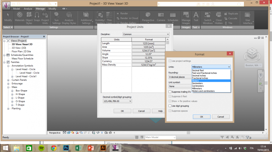
Step 4 _ To conduct a proper study on shading and lighting you must take into account the position of the building analyzed, then click "location" icon on the "analyze" bar.
Step 4 _ Per realizzare uno studio corretto sull'ombreggiamento/irraggiamento bisogna tenere in considerazione la posizione dell'edificio analizzato. quindi cliccate il comando "location" nella barra "analyze".
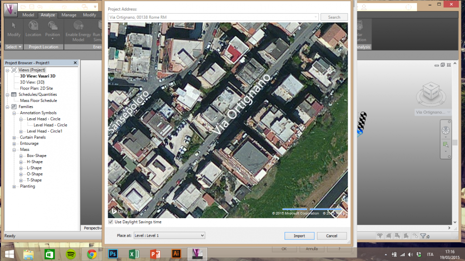
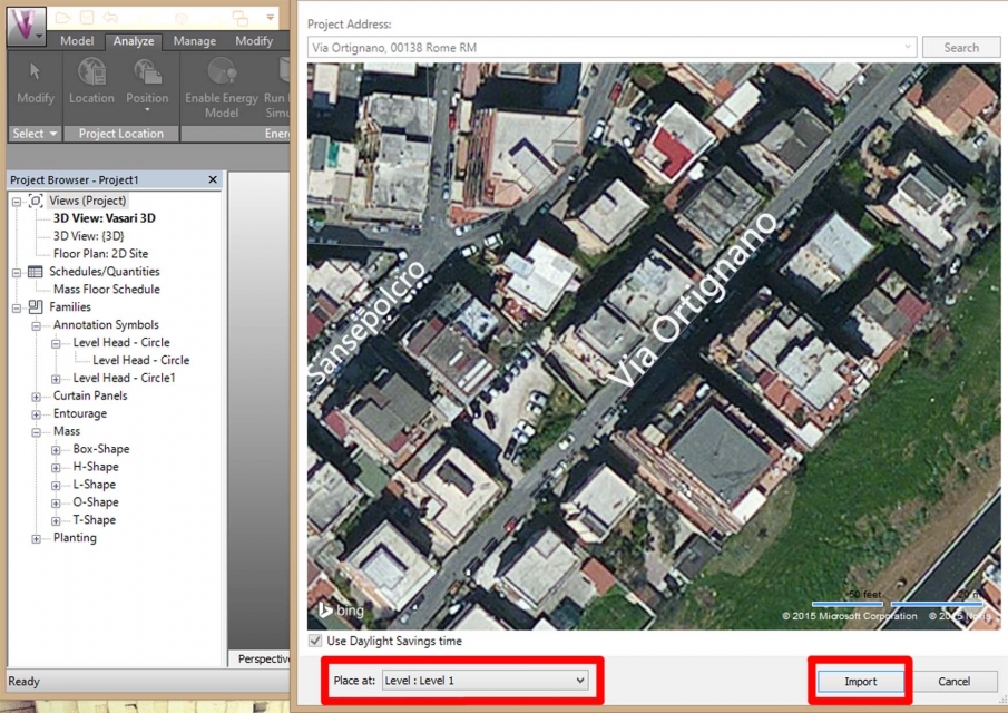
Step 5 _ Insert the address of the building. Make sure to select "Level 1", then click "import".
Step 5 _ Inserite l'indirizzo dell'edificio da studiare. Assicuratevi che il livello selezionato sia "Level 1" e cliccate sul comando "import".
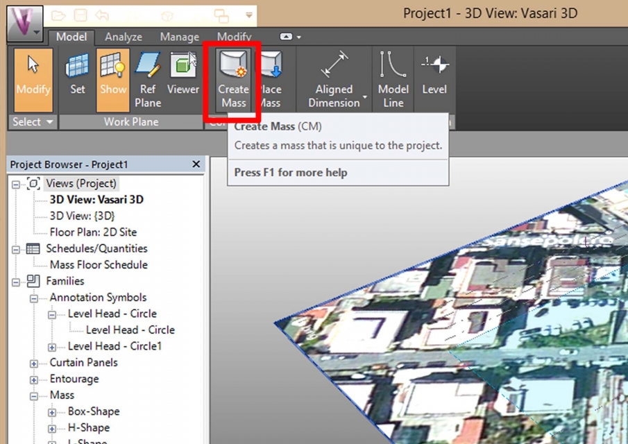
Step 6 _ Now select "create mass" on the "model" bar to start drawing.
Step 6 _ Ora selezionate "create mass" nella barra "model" per iniziare il disegno.
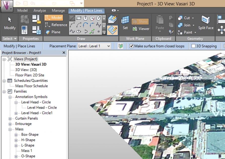
Step 7 _ Make sure to select the same commands as the picture (the yellow ones).
Step 7 _ Assicuratevi di aver selezionato gli stessi comandi dell'immagine (quelli evidenziati in giallo).
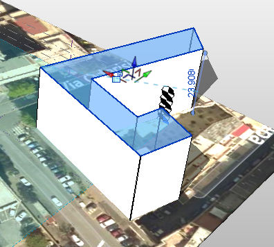
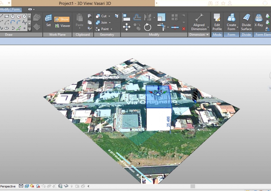
Step 8 _ To extrude the solid click and hold the blue arrow scrolling the mouse vertically. Type in the desired height using the keyboard.
Step 8 _ Per estrudere il solido tenete premuta la freccia blu e scorrete il mouse in verticale. Inserite l'altezza desiderata attraverso la tastiera.
Step 9 _ Extrude all the solids you have to take into account.
Step 9 _ Estrudete tutti i solidi che dovete prendere in considerazione.
Step 10 _ Once finished, click "finish mass".
Step 10 _ Una volta terminato cliccate sul comando "finish mass".
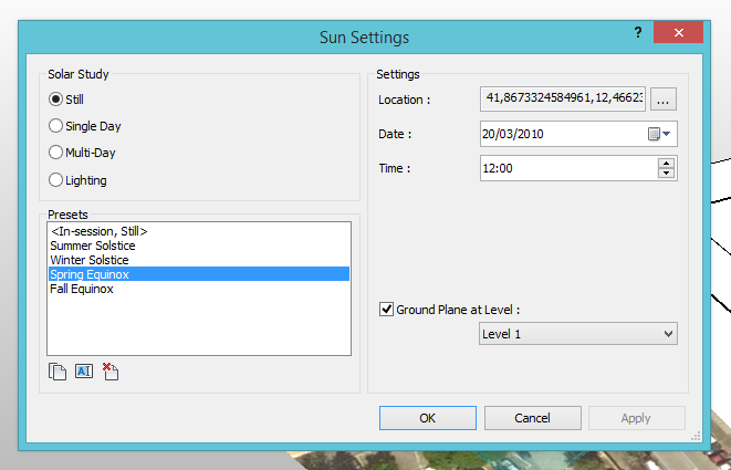
Step 11 _ Now create the desired set using the "sun setting" command on the "manage" bar.
Step 11 _ Ora create il set desiderato usando il comando "sun setting" nella barra "manage".
Step 12 _ Decide a day and time to analyze, then click "apply".
Step 12 _ Stabilite il giorno e l'ora da analizzare, poi cliccate "apply".
Step 13 _ To create a sun path click the sun icon on the bar below.
Step 13 _ Per inserire il "sun path" cliccate sull'icola con il sole nella barra in basso.
The house that we studied is located in Fidene - Rome - in Via Ortignano; this presents a lot of buildings of different heights, from 3 to 6 floors. In our case it's a building of 5 floors around 23 meters tall, next to it there are both a taller building (left side) and shorter (right side). With our analysis we've studied the response of the building to different hours of the day and different seasons.
L'abitazione che abbiamo studiato è situata nel quartiere Fidene - Roma - in Via Ortignano; questa presenta edifici di varie altezze tra i 3 ed i 6 piani. Nel nostro caso si tratta di una palazzina di 5 piani alta circa 23 mtetri e ad essa si affiancano un edificio piu alto (sul lato sinitro) ed uno più basso (sul lato destro). Con l'analisi svolta abbiamo studiato il comportamento dell'edificio in più ore della giornata e durante stagioni diverse.
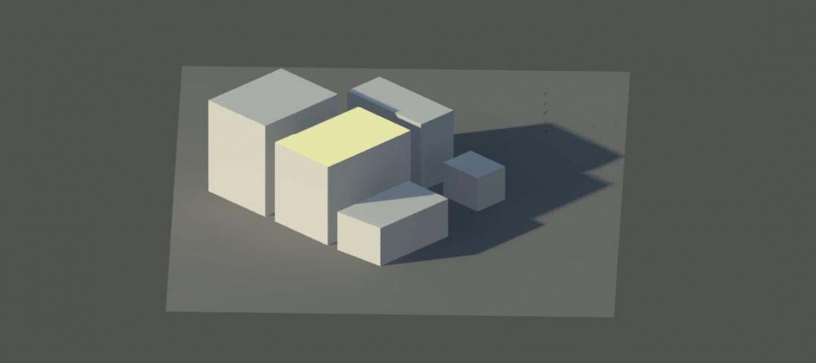
SUMMER SOLSTICE _ 21 GIUGNO
ORE 8:00
ORE 12:00
ORE 16:00
CAMERA VIEW _ ORE 16:00
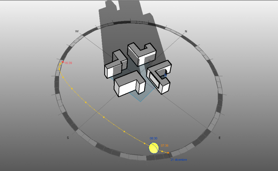
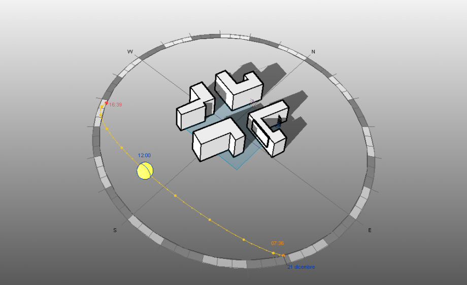
WINTER SOLSTICE _ 21 DICEMBRE
ORE 12:00
ORE 16:00
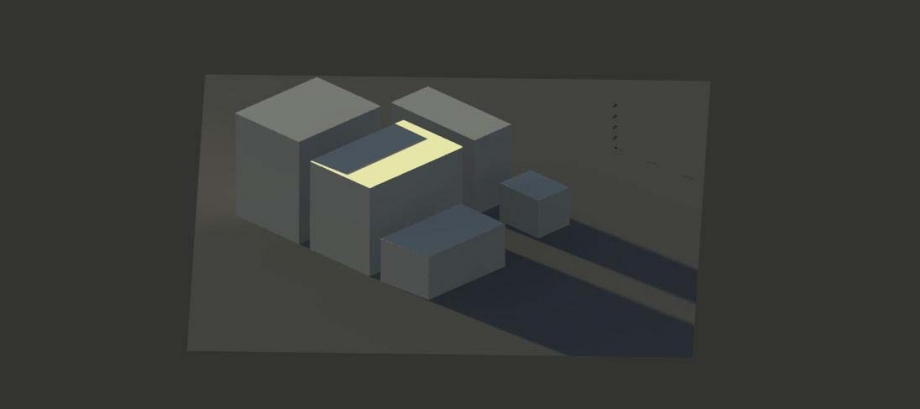
CAMERA VIEW _ ORE 16:00
VENERDI 20 MARZO
ORE 8:00
ORE 12:00
CAMERA VIEW AND PHOTO COMPARISON _ ORE 14:00
ORE 16:00
The result of our study is:
WINTER _ The facades Northwest and Southwest, because of the unfavorable position and proximity to the other buildings, remain in the shade for most of the day. The front Northeast is irradiated only in the early morning light, unlike the Southeast who enjoys sunlight throughout the day.
SUMMER _ A Northwest the building can enjoy the sunshine from early afternoon until sunset, hours when the facades North-East and South-East are shaded. The proximity to the building on the left side creates shadows on the facade Southwest throughout the day.
In conclusion we can say that the more advantaged facade is the Southeast as it receives sunlight during the cold winter days and resulting instead cooler (because shaded) in summer. The lack of buildings on the southern front is in favor of such a result. As for the north solar radiation is unfavorable as it occurs only during times warmer summer (from 12 to 16). The lack of sunlight in the facade Southwest is for the winter a disadvantage, but the summer is rather advantageous.
Dallo studio effettuato è risultato che:
INVERNO _ Le facciate Nord- Ovest e Sud-Ovest, proprio per la posizione sfavorevole e per la vicinanza agli altri edifici, rimangono in ombra per gran parte della giornata. Il fronte Nord-Est è irraggiato solo nelle prime luci del mattino, a differenza del prospetto Sud-Est che gode di luce solare per tutto l'arco della giornata.
ESTATE _ A Nord-Ovest le abitazioni possono godere della luce solare dal primo pomeriggio fino al tramonto, ore in cui le facciate Nord-Est e Sud-Est risultano ombreggiate. La vicinanza all'edificio sul lato sinistro genera ombre sulla facciata Sud-Ovest durante tutta la giornata.
A conclusione possiamo affermare che il fronte più avvantaggiato è quello Sud-Est in quanto riceve la luce solare durante le fredde giornate invernali, risultando invece più fresca (perchè ombreggiata) nel periodo estivo. La mancanza di edifici sul fronte Sud è a favore di tale risultato.
Per quanto riguarda la parte Nord l'irraggiamento solare è sfavorevole in quanto si presenta solamente durante gli orari estivi più caldi (dalle 12 alle 16). La mancanza di luce solare nella facciata Sud-Ovest è per il periodo invernale una condizione sfavorevole, ma per quello estivo risulta invece vantaggiosa.
Lun, 23/03/2015 - 17:25