


 Guendalina Tassi
Dom, 07/06/2020 - 19:05
Guendalina Tassi
Dom, 07/06/2020 - 19:05
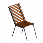
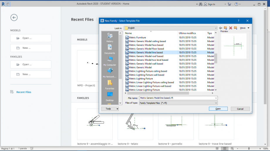
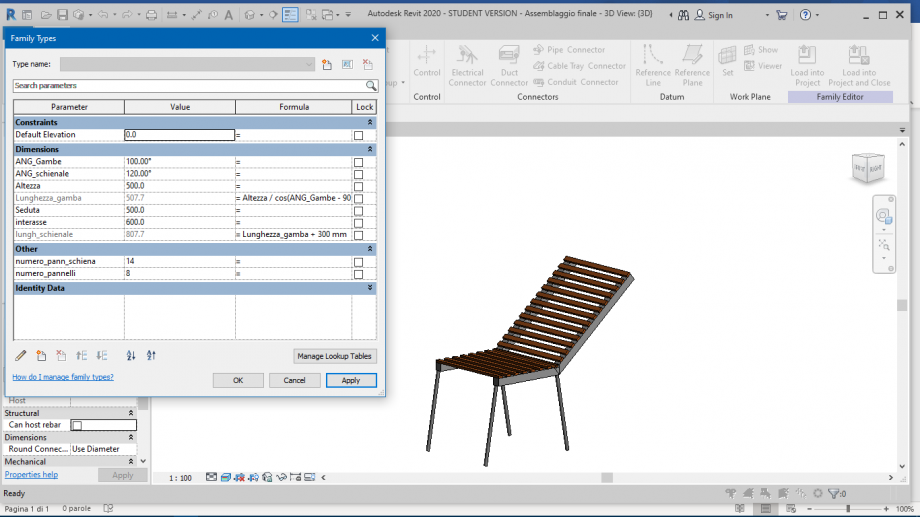
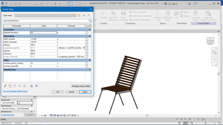
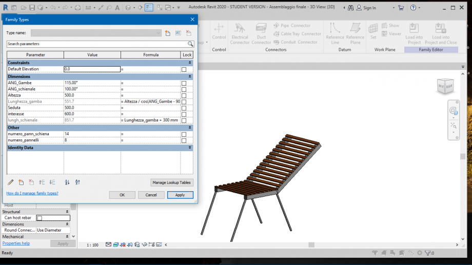
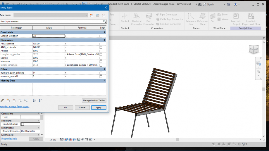
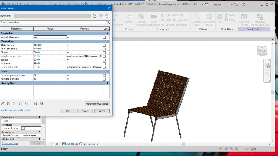
Partendo da un Metric Generic Model Line Based, ho iniziato a creare le mie famiglie che poi andrò ad assemblare per creare una sedia.
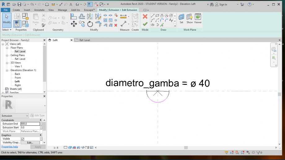
Sono partita dalle gambe della sedia, che ho voluto farle con un profilo circolare. Ho assegnato quindi un parametro alla lunghezza
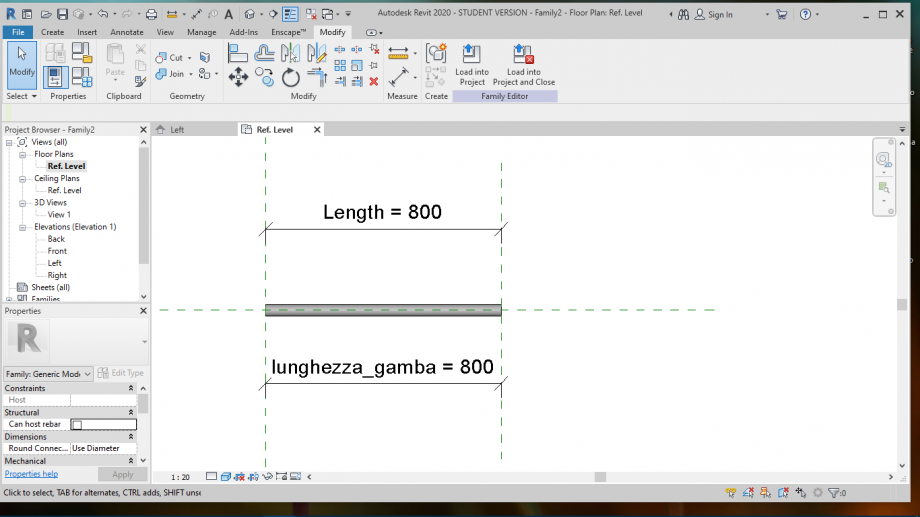
e al diametro.
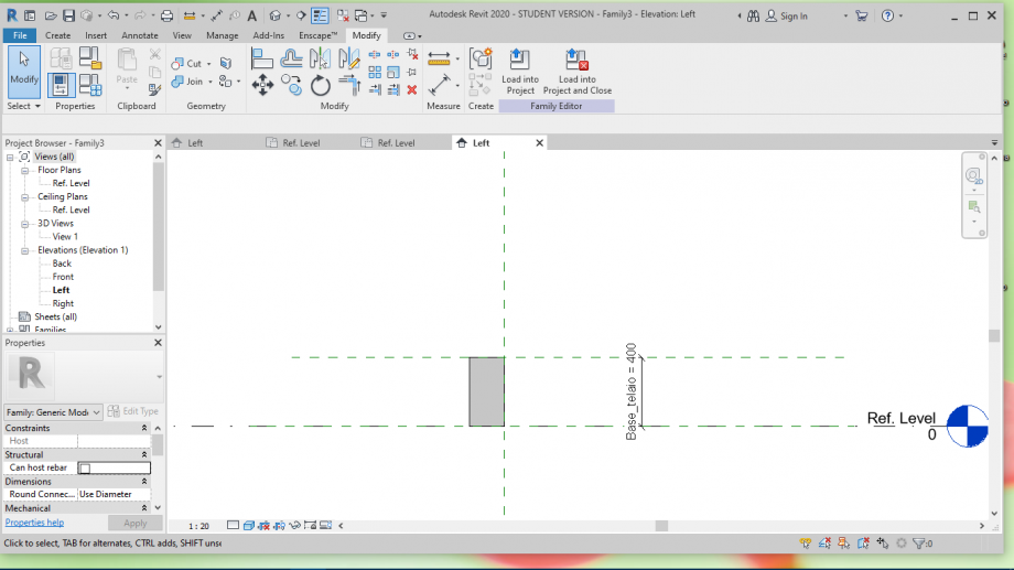
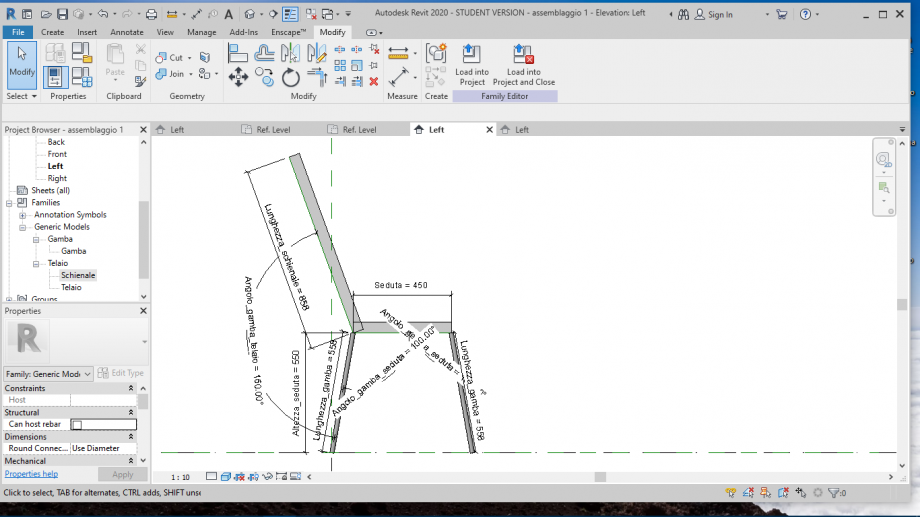
Successivamente ho creato una nuova famiglia, sempre basata su linea, per creare il "telaio" della sedia. Anche qui, come in quella precedente, ho assegnato dei parametri che mi serviranno più avanti: l'altezza del telaio, la lunghezza
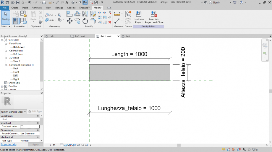
e infine la base.
La terza famiglia la apro con il Metric Generic Model, e qui vado ad impostare delle linee di riferimento che mi serviranno per lo "scheletro" del mio assemblaggio finale.
Inizio a parametrizzare tutto ciò che mi sarà utile: gli angoli delle gambe e dello schienale e le varie lunghezze che in seguito verranno modificate.
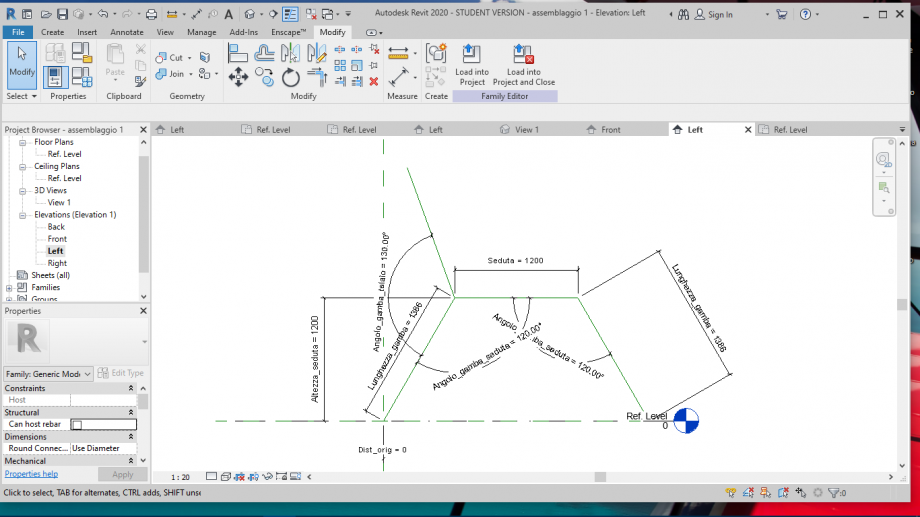
Essendoci angoli, lavorerò molto con le formule trigonometriche.
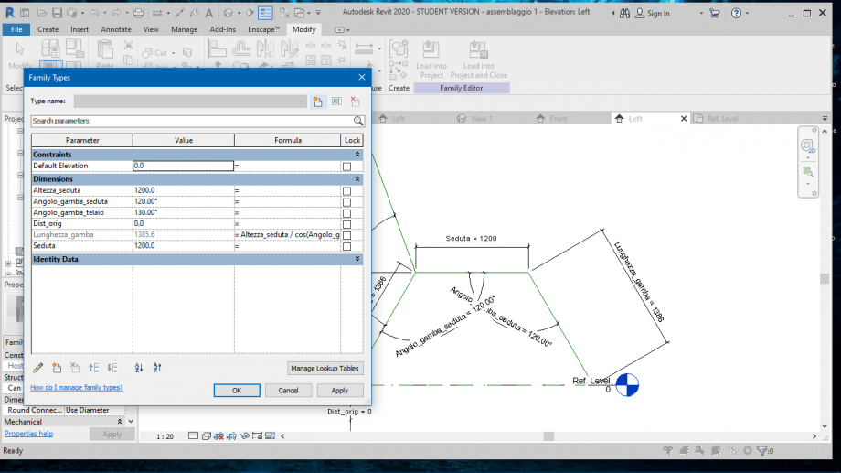
Dopo aver caricato le prime due famiglie, mi assicuro che tornino tutti i parametri e che il progetto funzioni.
Dopo di che creo una nuova famiglia dove andrò a progettare un singolo pannello, al quale ho dato un materiale,
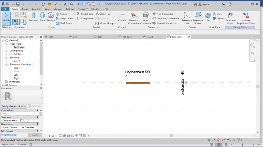
che posizionerò su un Metric Generic Model Face Based, e col quale andrò a creare, tramite Array, una "griglia"
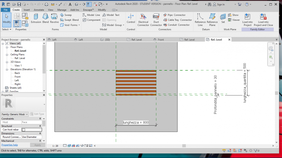
che posizionerò nell'assemblaggio finale sulla "seduta" e sullo "schienale" della mia sedia
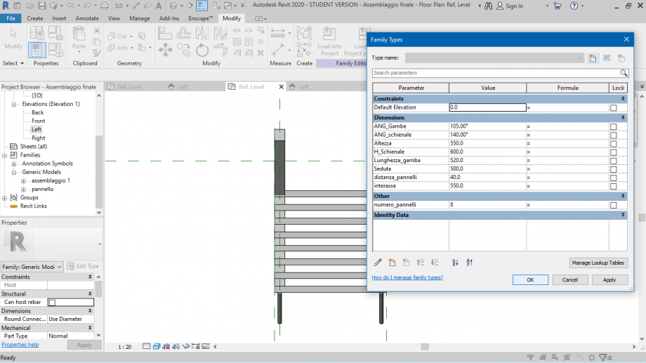
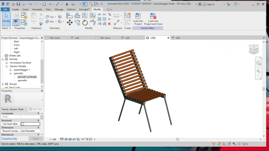
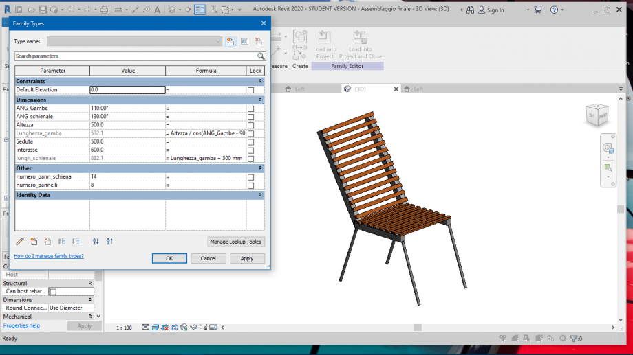
Infine, dopo aver collegato tutti i parametri con quelli "principali", posso modificare la sedia.
 vyacheslav.okhvat
Dom, 07/06/2020 - 18:14
vyacheslav.okhvat
Dom, 07/06/2020 - 18:14
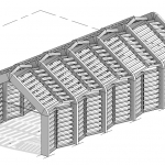
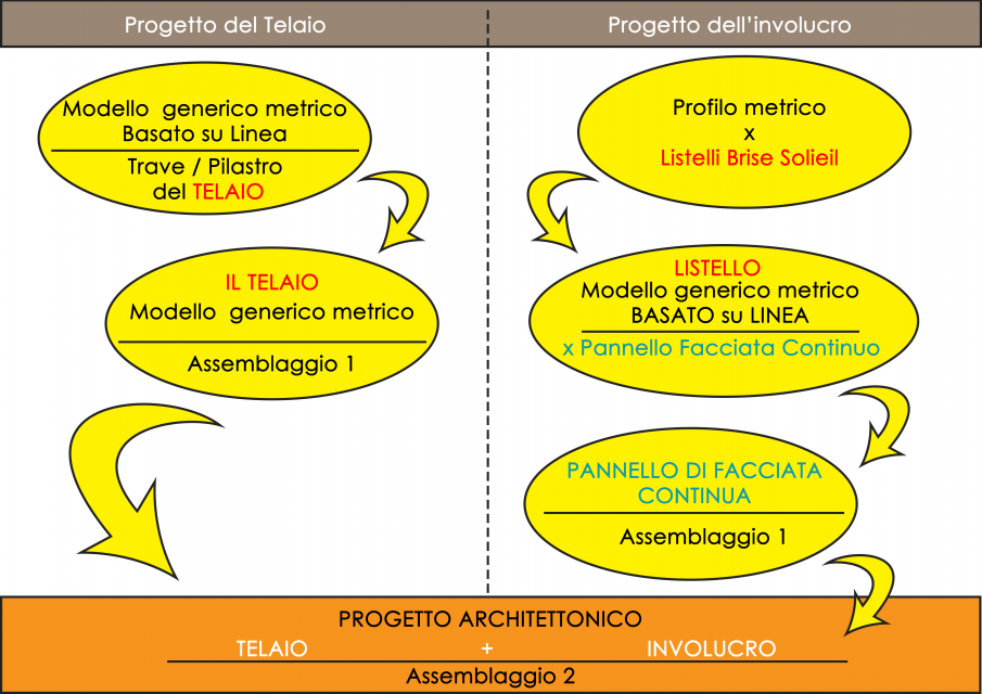
Sulla base dell'esercitazione precedente, ho ritenuto interessante continuare il progetto dei portali a capriate, aggiungendo alla struttura un sistema di rivestimento di tipo : Facciate continue . Ho organizzato il lavoro seguendo il seguente schema. Il mio obbiettivo era basato sulla possibilità di avere un buon controllo su tutte le parti della struttura.
1.Apriamo quindi una nuova famiglia in cui andremo a realizzare solo il profilo di estrusione. Facciamo questo per poter modificare i parametri di spessore e larghezza del profilo. Questo ci sarà utile più avanti.

2.Cosi come nell'immagine sottostante creiamo i piani di riferimento e vincoliamo ai piani il perimetro del profilo. Creiamo due parametri Base ed Altezza. Salviamo la famiglia.

3. Andiamo a creare ora una nuova famiglia che conterrà all'interno il singolo listello di frangisole.

4. In pianta creiamo una serie di linee di riferimento e aggingiamone dei parametri Istanza alla D, L, Lunghezza_tot. Questo per poter stirare o accorciare il listello nella famiglia in cui lo andremo ad inserire.


5. Andremo a creare due elementi distinti. Il primo sarà un perno centrale circolare, fulcro di rotazione dei pannelli brise soleil. L'altro riguarda proprio il pannello frangisole. L'immagine sotto illustra il procedimento per la creazione del pannello. Utilizzo lo strumento Estrusione Lungo un percorso, creo due quote Marg, L_tot ed allineo il percorso di estrusione alla linea di riferimento.

6. Seleziono ora il profilo creato precedentemente e termino la creazione dell'oggetto. Specchio l'oggetto rispetto al piano di riferimento centrale, entro nel pannello di modifica dell'estrusione e vincolo la linea di percorso di colore violaceo alla linea di riferimento di colore verdastro.

7. Ora assegno al profilo della sezione dei due pannelli i parametri B ed H, che serviranno a determinare lo spessore e la profondità del pannello stesso.

8. Nell'immagine in basso creo l'asta tubolare, il perno di rotazione dei pannelli e gli assegno un profilo circolare che disegno nella vista a Destra. Ora devo vincolare il percorso di estrusione alle linee di riferimento ed assegnarli il vincolo di Lunghezza L

9. L'oggetto Estrusione Lungo un Percorso ha il parametro di Angolo Pre-settato, che possiamo attribuire ad un parametro da noi creato e quindi gestire in una nuova famiglia successivamente.

10.


11.

12.

13.

14.

15.

16.

17.

18. Iniziamo ora la fase dell'assemblaggio 2 - La creazione di un Nuovo Progetto Architettonico

19

20.

21.

22.

23.

24.

25.

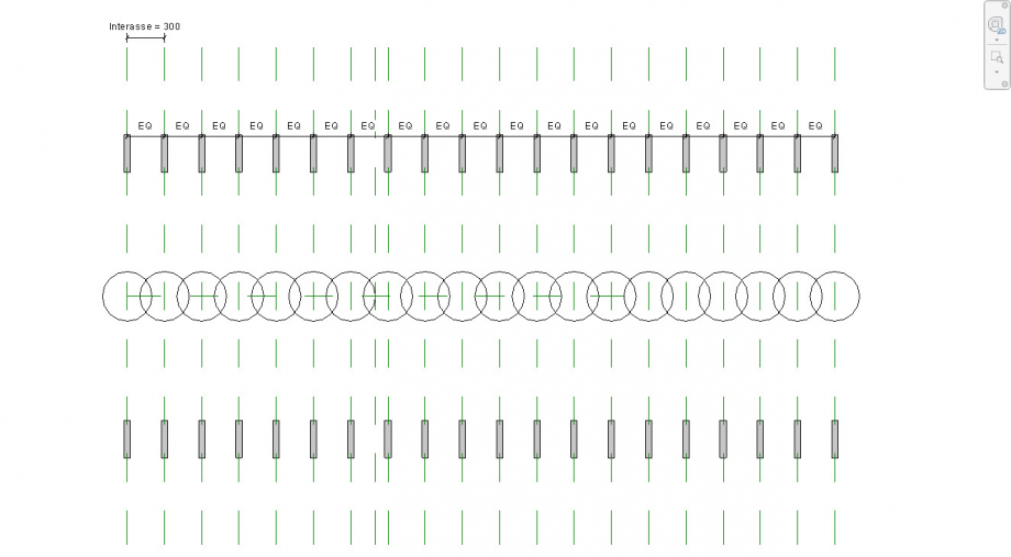
26. Ho aggiunto un po di dettagli in pianta, ho aumentato il numero delle campate e ho collegato i fili strutturali trasversali, di cui il filo B è bloccato (pinnato), mentre G ed H si possono muovere. Ho aggiunto un nuovo parametro Luce, con una breve formuletta, in modo che i fili strutturali siano sempre in asse con il pilastro. Questo mi servirà successivamente, quando dovrò inserire le Curtain Wall.
I telai sul filo A e C sono vincolati al filo strutturale B, esattamente al centro.

27. Tutti i parametri evidenziati in rosso, nell'immagine sottostante, indicano i parametri relativi al TELAIO. Tutti gli altri sono relativi alla Gestione della Curtain Wall.

28.

29.

30.

31.

32.
33.

34.

35.

36.

37.

38.

39.

40.

41.

42.

43.

Dom, 07/06/2020 - 18:15
 vyacheslav.okhvat
Lun, 01/06/2020 - 18:36
vyacheslav.okhvat
Lun, 01/06/2020 - 18:36
1. Creo una nuova famiglia di tipo: Modello generico basato su linea. Questo mi permette di creare un elemento solido, che potrà essere usato sia come trave che come pilastro della mia struttura.
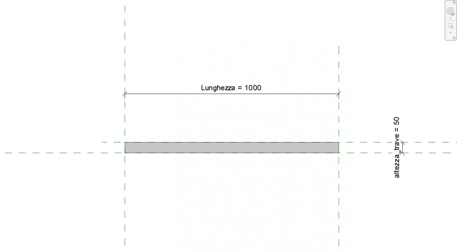
2. Creo quindi un estrusione vincolata a tutti e quattro i piani di riferimento. Creo una quota e la parametrizzo con parametro tipo. Nella vista ( Prospetti/Destra ) creo altri 2 piani di riferimento, quote equidistanti e una quota parametrica ( tipo ), che sarà la base della trave. Vincolo la trave ai due piani di riferimento.
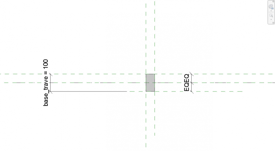
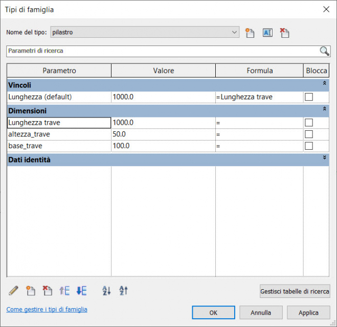
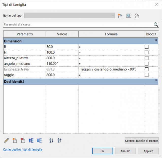
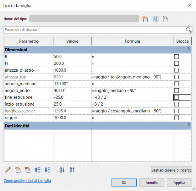
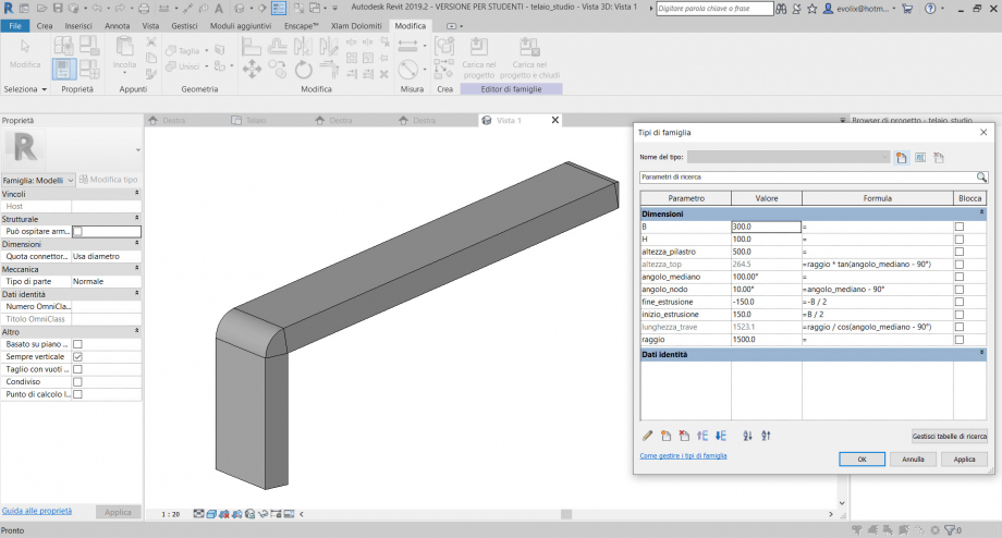
3. Nella scheda sotto si possono vedere i tre parametri tipo impostati, ai quali sono associate le quote nella famiglia. Il vincolo Lunghezza avrà la formula, ossia sarà uguale al vincolo Lunghezza_trave. Creo inoltre due nuovi tipi nella stessa famiglia, di cui uno pilastro l'altro trave.
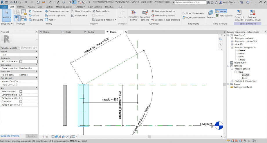
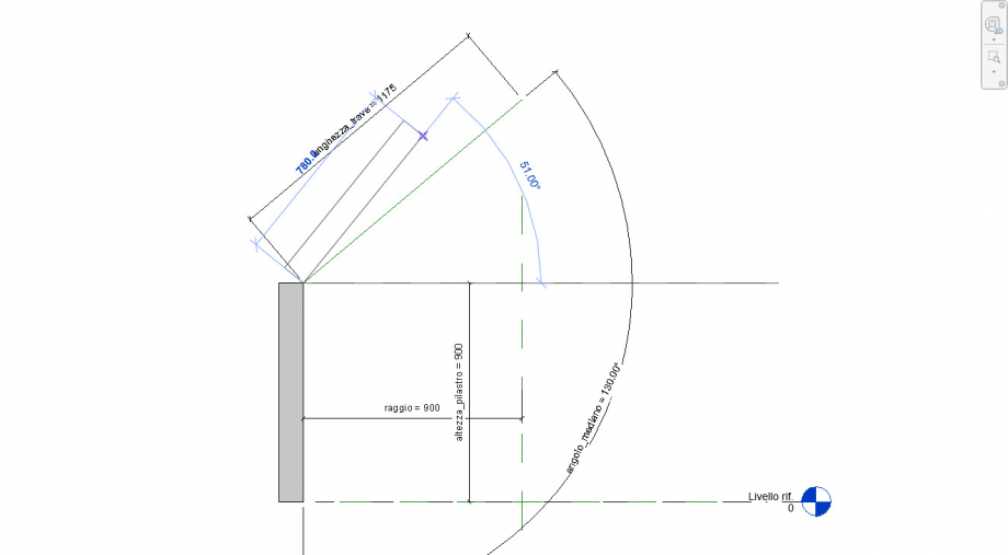
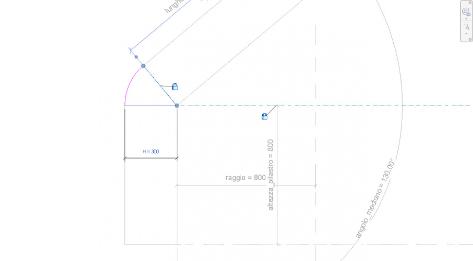
4.Salviamo la famiglia e ne iniziamo a creare una nuova. Questa volta di tipo: Modello generico metrico. Ci spostiamo nella vista a destra ( Prospetti/Destra ) ed iniziamo a creare una linea di riferimento verticale. Poi creiamo una linea di riferimento obliqua attaccata alla prima ad un estremità. Creo 3 parametri tipo : (raggio, lunghezza_trave, angolo_mediano).

5. Il parametro lunghezza sarà dato da una formula : Lunghezza_trave = raggio / coseno (angolo_mediano - 90°). In questo modo al variare della dimensione del raggio, o dell'inclinazione dell'angolo_mediano, la lunghezza_trave si adatterà a sua volta toccando l'asse di simmetria.
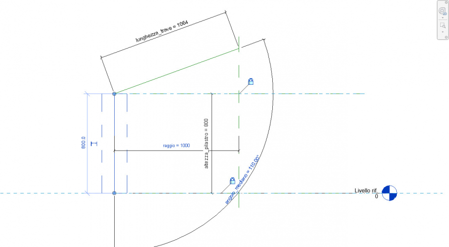
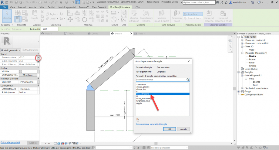
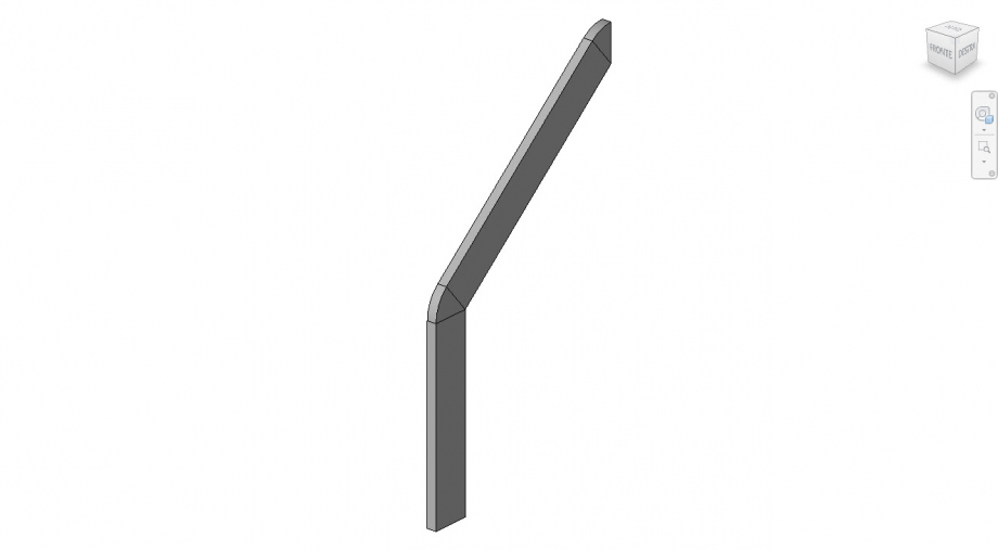
6. A questo punto creo un nuovo piano di riferimento orizzontale passante per l'angolo formato dalle due linee di riferimento. Creo un nuovo parametro tipo (altezza_pilastro) e gli assegno la quota. Vincolo ora le due estremità della linea di riferimento tra i due piani di riferimento. Salvo il file con il nome: telaio.
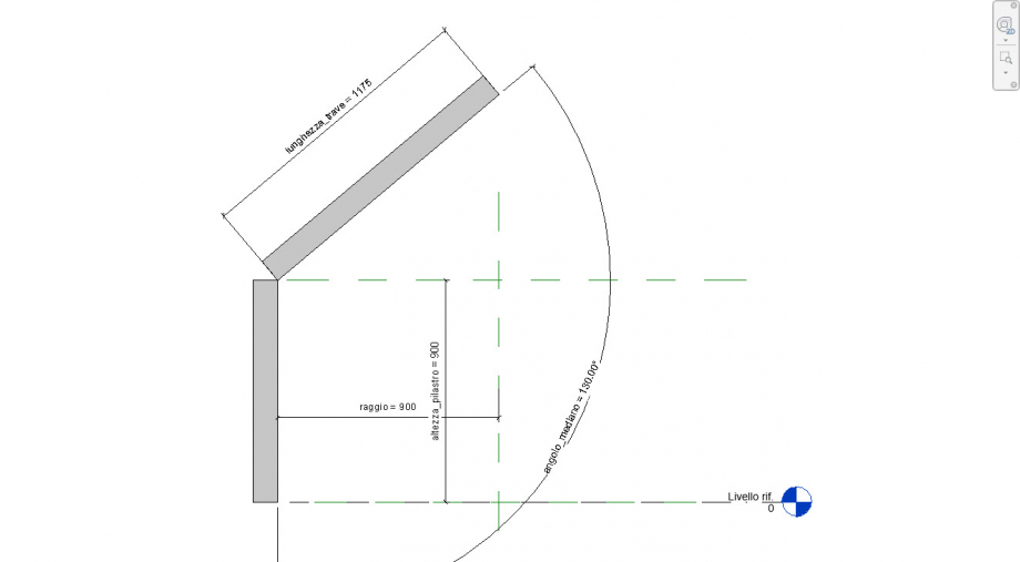
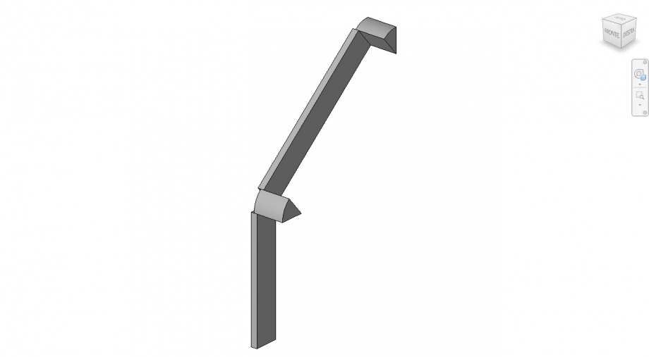
7. Imposto ora il piano di riferimento sulla linea verticale creata in precedenza ed importo la famiglia della trave nella famiglia telaio. Aggiungo il pilastro come nell'immagine. Devo prima di tutto vincolare il pilastro solamente alla linea di terra e alla linea di riferimento verticale. Modifichiamo i parametri del pilastro, in cui la lunghezza_trave sarà uguale ad altezza_pilastro.
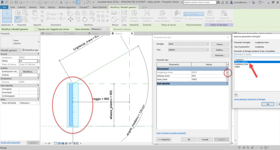
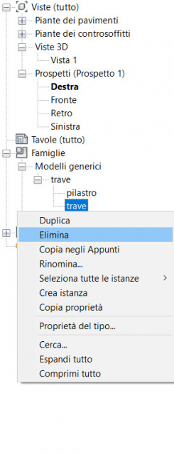
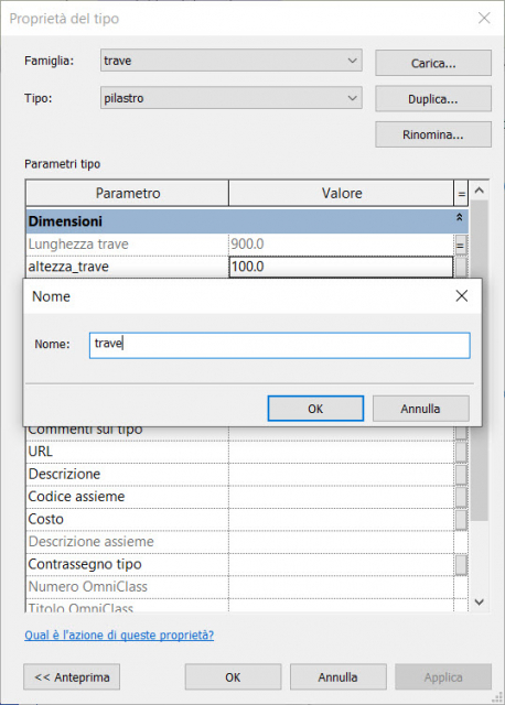
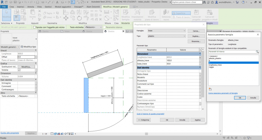
8. Ora bisogna fare la stessa cosa con la trave. A volte può succedere che i parametri non funzionano. Ho riscontrato questo problema nell'assegnazione del parametro lunghezza_trave alla trave inserita. Innanzitutto cancelliamo il tipo trave dalla famiglia importata e ne creiamo uno nuovo. Selezioniamo il pilastro, facciamo duplica / trave / OK.
9. Inseriamo ora la trave nella scena in questo modo, dall'estremità del pilastro. Ora allineiamo la trave alla linea di riferimento e la vincoliamo. Cambiamo il parametro della lunghezza = lunghezza_trave, cosi come abbiamo gia fatto con il pilastro.
10. Ora proviamo a cambiare i valori ai parametri che abbiamo assegnato e vediamo se la parti seguono le regole.
11. Aggiungiamo due nuovi parametri B ed H rispettivamente per poter modificare la base e l'altezza delle sezioni. Assegnamo questi due alle proprietà del pilastro e della trave.
12. A questo punto nella famiglia telaio vado a creare una nuova estusione.Disegno i contorni della geometria da estrudere e li vincolo rispettivamente uno al piano di riferimento e l'altro alla faccia della trave. Assegno il parametro H come quota alla lunghezza della base.
13. Ora se proviamo a cambiare i valori dei parametri assegnati vedremo che il nodo segue le variazioni della trave e del pilastro. Stessa operazione la vorrei riproporre nel nodo alto che ora andremo a creare.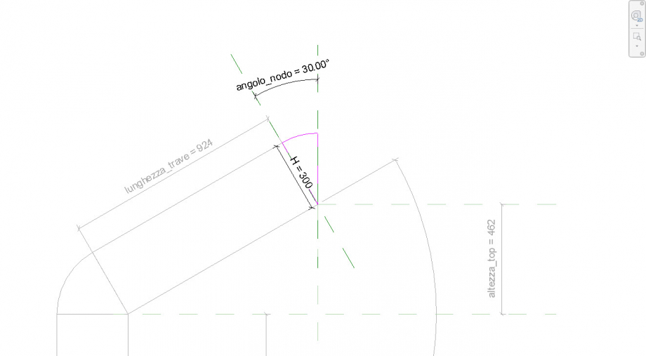
14. Aggiungiamo un piano di riferimento fuori dal gruppo estrusione e gli assegnamo un parametro : altezza_top = raggio * tangente dell'(angolo_mediano - 90°). Al variare del raggio o dell'altezza del pilastro o dell'angolo mediano, cambierà rispettivamente l'altezza del nodo_alto. Creiamo ora una nuova estrusione, all'interno della quale due piani di riferimento, un parametro angolare_nodo = angolo_mediano - 90° e un parametro H. Usciamo dal comando e controlliamo se tutto funziona correttamente.
14. A questo punto vorrei fare in modo che la larghezza del nodo rispettasse il parametro B che rappresenta la base dei nostri trave e pilastro. Per fare ciò, conosco il funzionamento dello strumento estrudi, che è basato principalmente su due parametri INIZIO e FINE. Devo assegnare a questi due i miei nuovi parametri
15. Controlliamo ora se cambiando i valori tutto funziona come prestabilito.
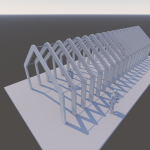
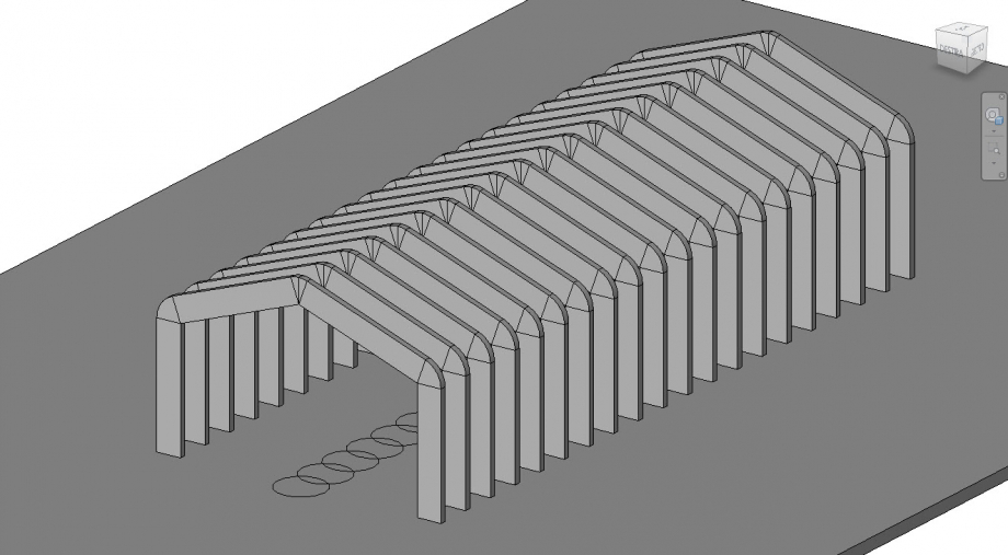
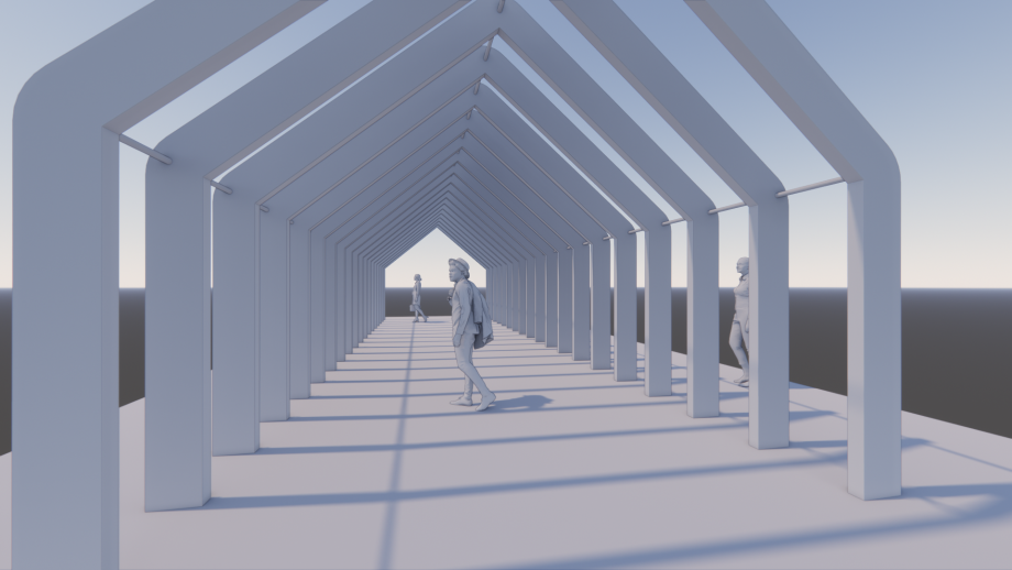
16. Proviamo ora a creare una struttura variabile formata da una serie di campate e riassegnamo dei nuovi parametri alla nuova famiglia basata sul modello generico metrico che andremo a creare.
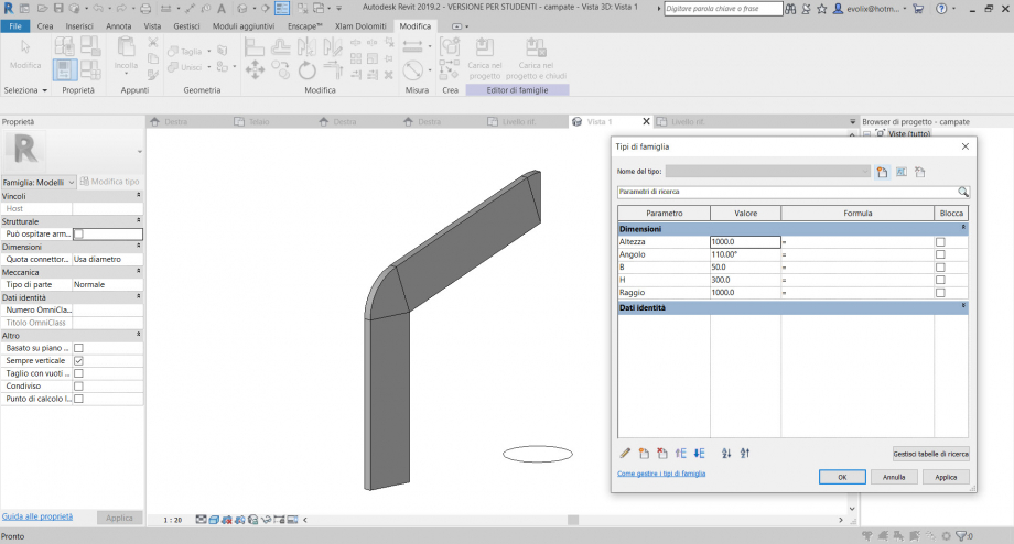
17. Ho creato una serie di piani di riferimento con lo strumento serie lineare. Ho vincolato con le quote i piani di riferimento e ho creato un solo parametro che ho chiamato "Interasse". Ho copiato, specchiato e vincolato le mie campate ai piani di riferimento.
18. Da questo momento le possibilità di arricchiche il modello o giocare con le variabili attribuite sono infinite
 vyacheslav.okhvat
Lun, 01/06/2020 - 17:34
vyacheslav.okhvat
Lun, 01/06/2020 - 17:34
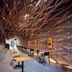
Kengo Kuma. Starbucks coffee, Dazaifu Shrine
Ho avuto la fortuna di fare un viaggio in Giappone nel mese di Agosto. Non è proprio il periodo più adatto per fare questo viaggio, per una questione strettamente di carattere climatico. Ad Agosto c’è un umidità dell’aria costante oltre il 90% e le temperature che oscillano tra i 34 ed i 38°C. Per questo motivo non ce da meravigliarsi se per le strade incontrate persone in abiti da ufficio con camicie a maniche corte ed un asciugamano bianco sul collo, ma questo è del tutto normale. La mia permanenza è durata un mese, che ho speso nel Sud del Giappone, nella Kyushu area, dove ho avuto il privilegio di immergermi nella cultura giapponese. Vivevo nella città di Fukuoka, dove servono il miglior Ramen di tutto il Paese, cosi anche come il resto della cucina meridionale, rinomata ed apprezzata. Dopo aver visitato diversi Templi Shintoisti, cimiteri, Pagode, dopo aver attraversato i portali sacri (Torii), immersi nella fiabesca natura dei giardini giapponesi, ho iniziato la ricerca di Architetture contemporanee. Il mio primo incontro con un opera di Kengo Kuma è stato durante una passeggiata sulla via sacra di Dazaifu Shrine. Il Progetto è un negozio su commissione di Starbucks, inserito in un contesto commerciale storico. Questa via, in realtà è un percorso sacro, che viene scandito da una serie di portali Torii lungo il viale, ai lati del quale corrono ristoranti tipici, botteghe artigianali e negozi tradizionali.
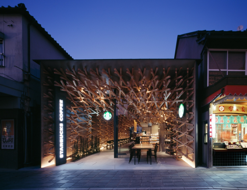
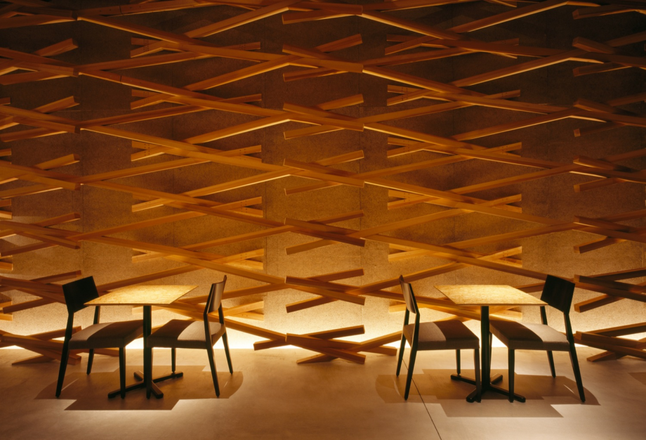
L’elemento che caratterizza in modo essenziale l’aspetto del negozio è il modo in cui si relaziona con la strada, su cui ogni giorno migliaia di visitatori del Tempio passano a piedi. La caffetteria infatti, ha solamente una grande vetrata verticale senza montanti a vista (frameless), che separa l’interno del negozio dall’esterno. Dalla strada quindi, si scopre il guscio, o la struttura portante, fatta di lastre in cemento armato ed il bellissimo rivestimento ligneo, caratteristico dell’architettura di Kengo Kuma. Gli elementi lignei che rivestono i tre lati del negozio (le due pareti ed il soffitto), sono in legno di Sugi e formano una struttura di elementi retti accatastati, che sono in parte vincolati alla struttura “Madre” in cemento armato ed in parte uniti tra loro in modo reciproco.
Un apparente casualità di elementi sovrapposti, che percepiamo all’ingresso della caffetteria, seguono in realtà delle ben precise regole costruttive, facilmente individuabili da una vista perpendicolare alla parete.
Quali sono in realtà le caratteristiche chiave di un nodo reciproco
Il nodo è formato da tre o più travetti, che si incontrano nell’estremità e generano delle forze esterne uguali e contrarie, che si convertono in modo reciproco in azioni interne al materiale. Alcuni esempi dei nodi più noti li troviamo nelle cupole geodetiche, nelle strutture Tensegrity, nel packaging.

L'immagine mostra uno schema semplificativo di come le forze si generano e si annullano in modo reciproco, dovute alla sovrapposizione di elementi.
Tornando a Starbucks Coffee, ho cercato di capire in dettaglio di come l’Architetto abbia realizzato il rivestimento. Tengo presente che il Giappone ha tramandato con sapienza una cultura millenaria in cui le strutture in legno hanno sviluppato tecniche dei nodi ad incastro, senza l’uso viti, staffe o chiodi. Una cultura in cui la carta è l’oggetto dei più svariati esercizi geometrici e l’Origami ne è il risultato.
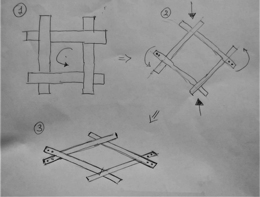
Nell’immagine sopra è rappresentato il metodo adottato. Si tratta di un nodo quadrato formato da 4 elementi retti. La struttura è ruotata ad angolo e vincola le due estremità alle pareti in calcestruzzo. Una pressione sulle estremità inferiore e superiore permette la rotazione delle aste nel punto in cui si incontrano, passando cosi da un angolo di 90° una rispetto all’altra, ad un angolo più ampio formando la figura di un rombo. Vengono poi fissate tutte le aste ma solo ai margini opposti tra loro. Vengono poi duplicate, sovrapposte e ripetute in tutte le direzioni, creando una maglia geometrica continua.
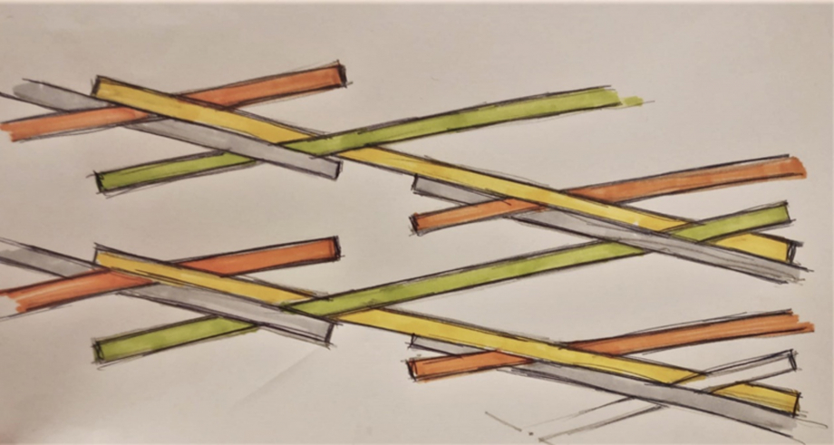
Si nota nell’immagine sotto, di come alcuni dei travetti sono ancorati al muro, per mezzo di staffe a scomparsa e spinotti senza testa. Per aumentare invece l’estensione lineare di un elemento ligneo, ha utilizzato una staffa piatta a scomparsa, nell’anima tra i due travetti e due spinotti per estremità, a bloccare lo scorrimento.
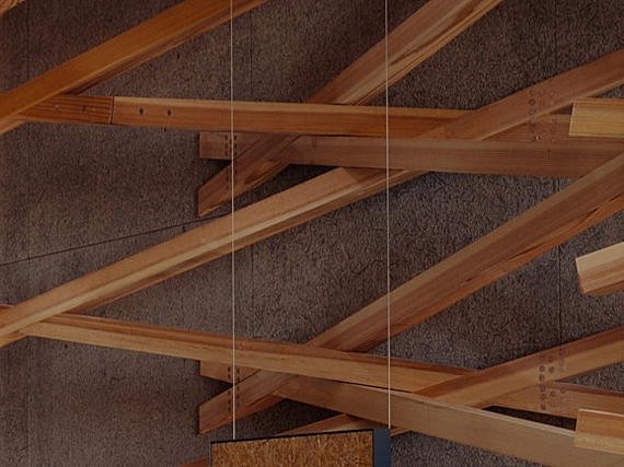
Il risultato è un sorpendende rapporto tra l'accatastamento degli elementi lignei di colore naturale con il fondo grigio del calcestruzzo. L'ambiente è illuminato principalmente dalla luce naturale che penetra all'interno attraverso un fascio di lucernari in copertura.
Lun, 01/06/2020 - 18:28 TOM.SCIUME
Dom, 31/05/2020 - 23:45
TOM.SCIUME
Dom, 31/05/2020 - 23:45
Per la composizione ho iniziato posizionando cinque componenti, di cui quattro parallelepipedi nei punti più estremi e un cubo al centro. I valori numerici delle dimensioni di partenza sono gli stessi (2500, 300, 300) ma si alternano a parametri diversi a seconda del componente che prendiamo in considerazione. La profondità, ad esempio, può valere 2500 per un componente e 300 per un altro. Successivamente ho copiato i quattro componenti in sequenza, direzionati verso il cubo, ponendo una distanza di 300 tra un solido e l'altro e diminuendo di 200 il parametro con valore iniziale 2500. Da ognuno dei quattro componenti, quindi, si avvia una sequenza che si sviluppa in ordine "decrescente".
Lun, 01/06/2020 - 01:27