 Petrelli_Palombi
Lun, 27/04/2015 - 16:13
Petrelli_Palombi
Lun, 27/04/2015 - 16:13
PUNTO 1 - Analisi della radiazione solare
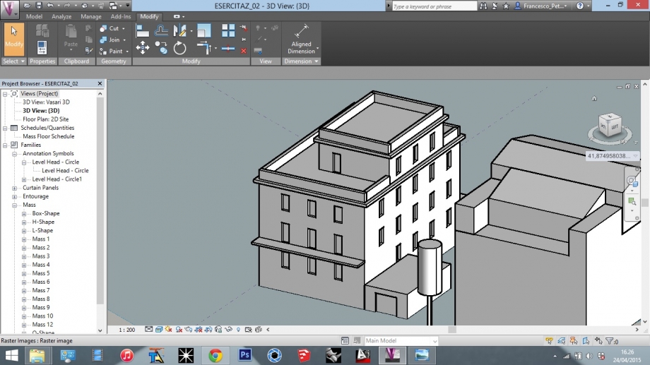
In questa esercitazione consideriamo nel nostro modello elementi più specifici, quali bucature, aggetti, balconi ed eseguiremo l'analisi della radiazione solare sulle facciate del nostro edificio e al suolo.
MODELLAZIONE
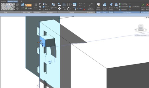
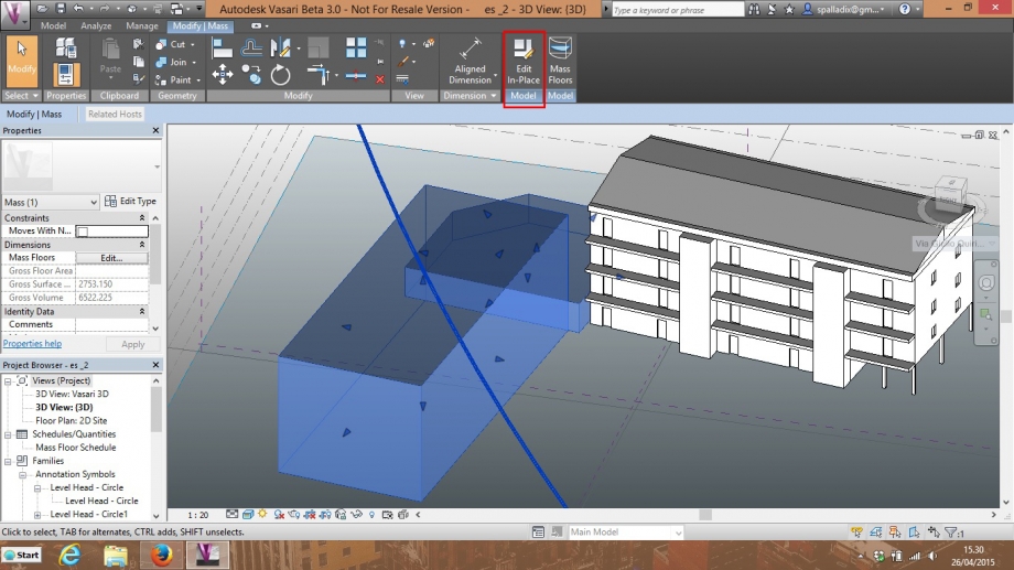
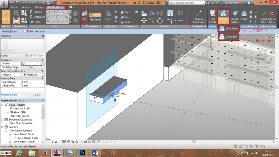
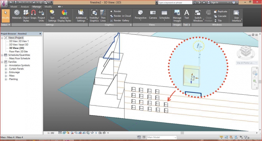
01_Seleziono il volume da modellare e lo edito con il comando Modify|Mass --> Edit in-Place.
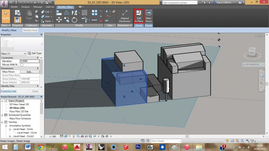
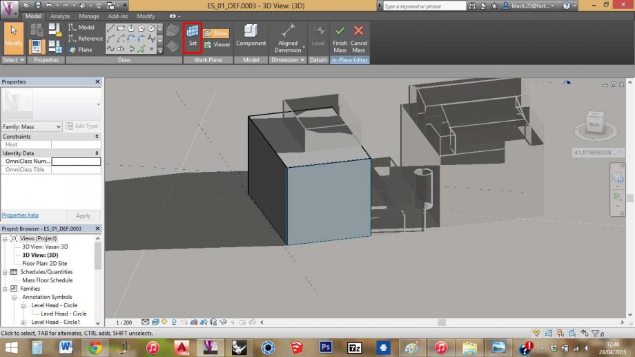
02_Imposto il piano di lavoro con Model --> Set.
03_Creo una griglia di riferimento per posizionare le bucature e gli aggetti.
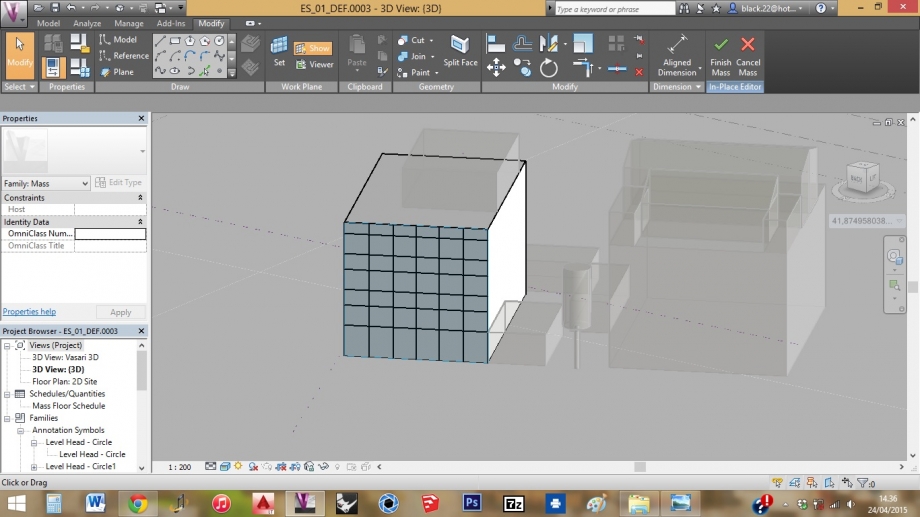
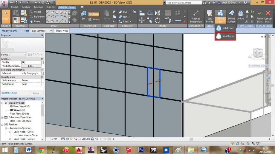
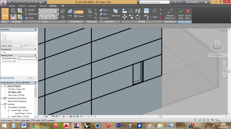
04_Disegno un rettangolo sulla facciata da modellare. Con il comando Modify|Form --> Create Form --> Void Form estrudo il rettangolo per creare un vuoto sulla facciata.
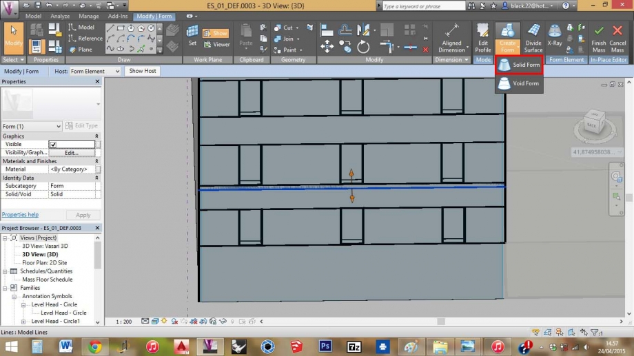
06_Ripeto il procedimento per tutte le finestre. Per il balcone uso il comando Modify|Form --> Create Form --> Solid form ed estrudo il rettangolo disegnato.
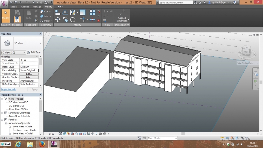
07_Concludo la modellazione con il comando Finish Mass.
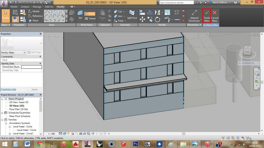
08_Utilizzando gli stessi comandi completo l'edificio con cornicioni e parapetti.
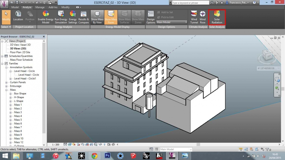
ANALISI DELLA RADIAZIONE SOLARE
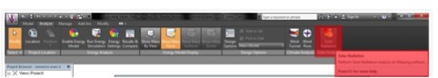
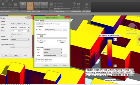
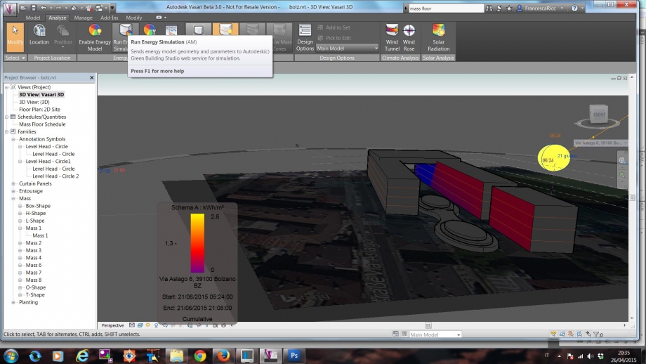
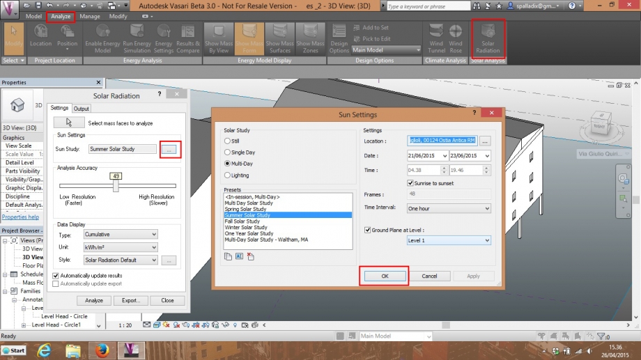
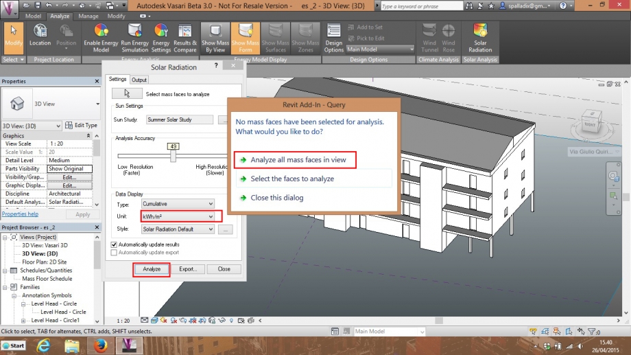
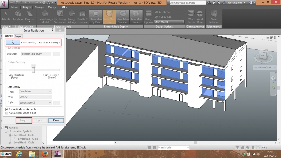
Ora possiamo utilizzare il comando Analyze --> Solar Radiation
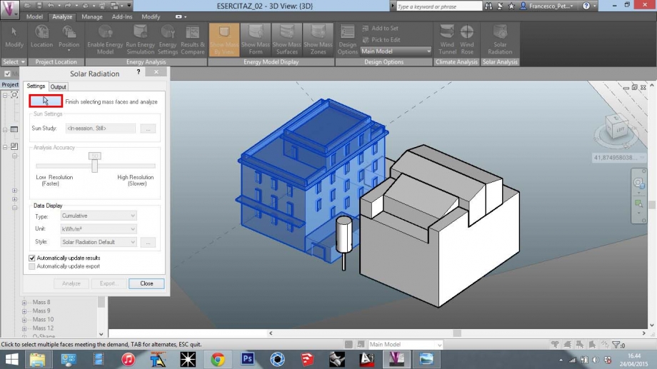
01_Seleziono le facce da analizzare e clicco su Finish selecting mass faces and analyze.
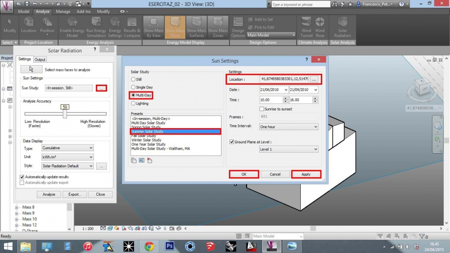
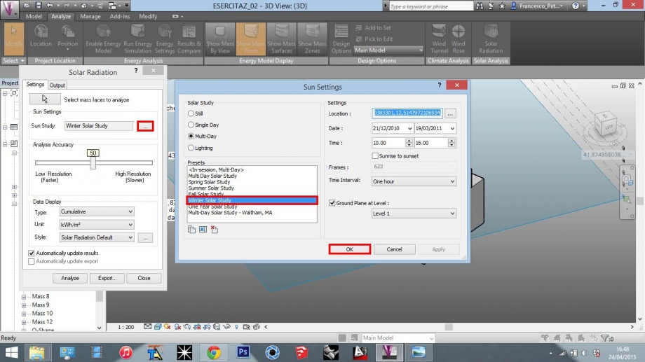
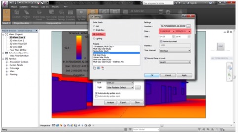
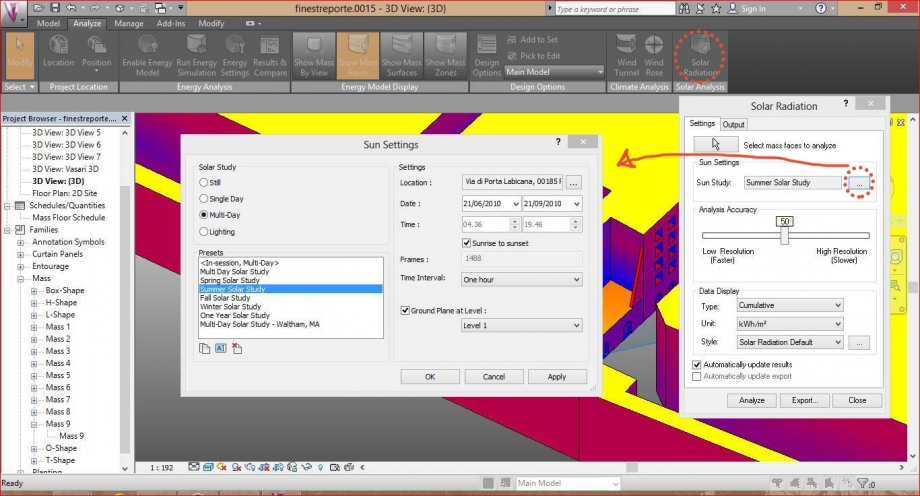
02_Cliccando su [...] dell'impostazione Sun Study, si aprirà la finestra Sun Settings, in cui modifico le impostazioni in base allo studio da condurre:
-Solar Study --> Multi-Day
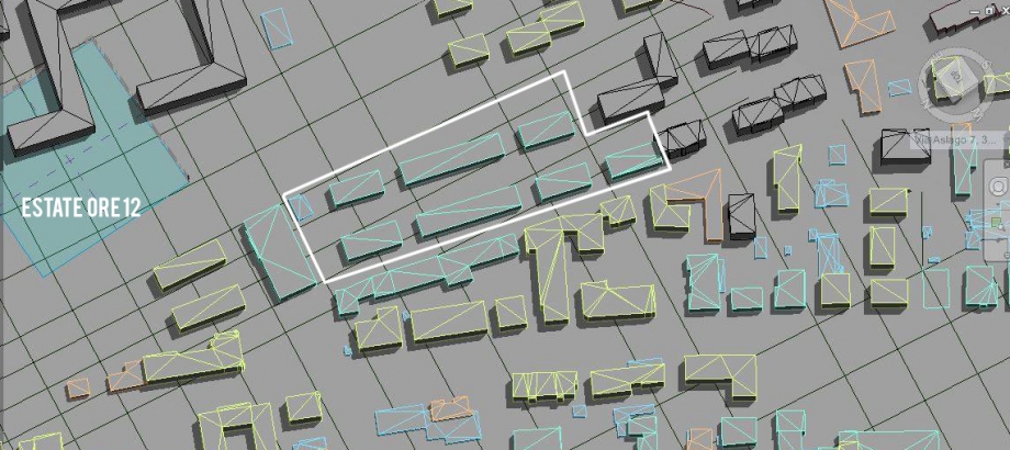
-Solar Study --> Summer Solar Study (per l'estate)
-Imposto la Location
Clicco poi su Apply e poi OK.
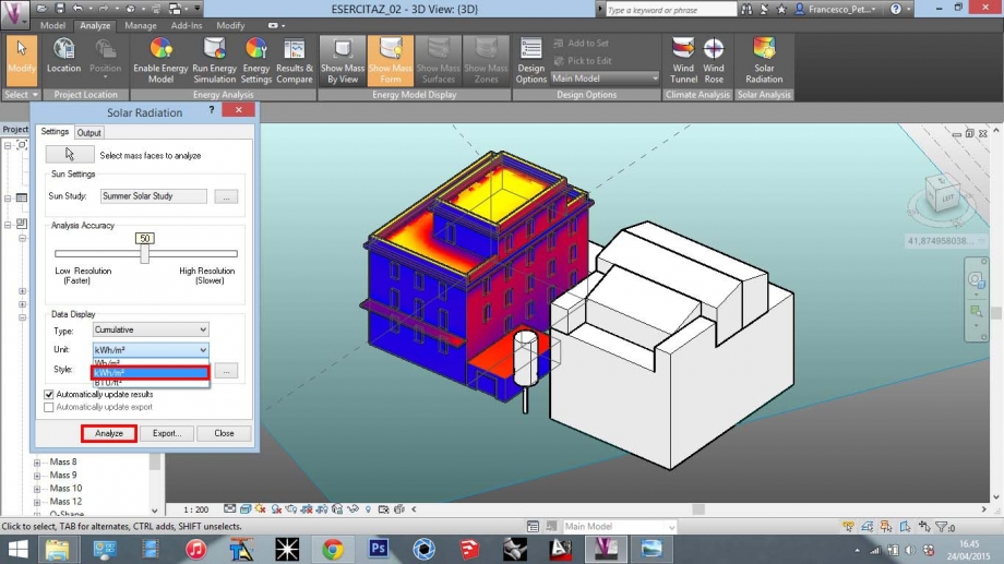
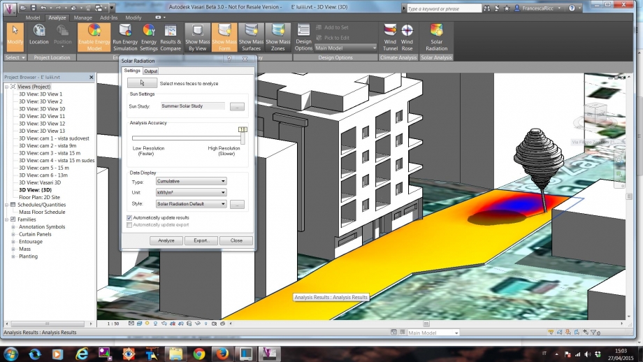
03_Imposto l'unità di musura: Unit --> kWh/mq e faccio partire l'analisi cliccando su Analyze.
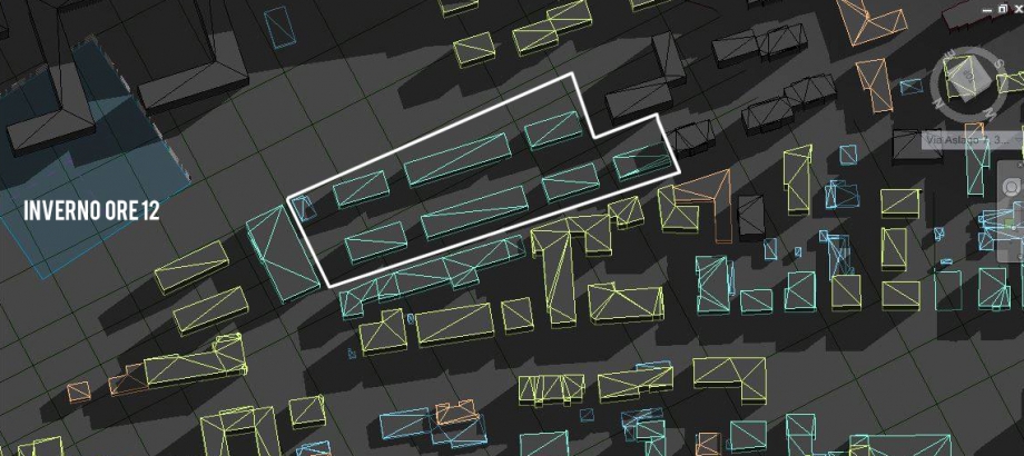
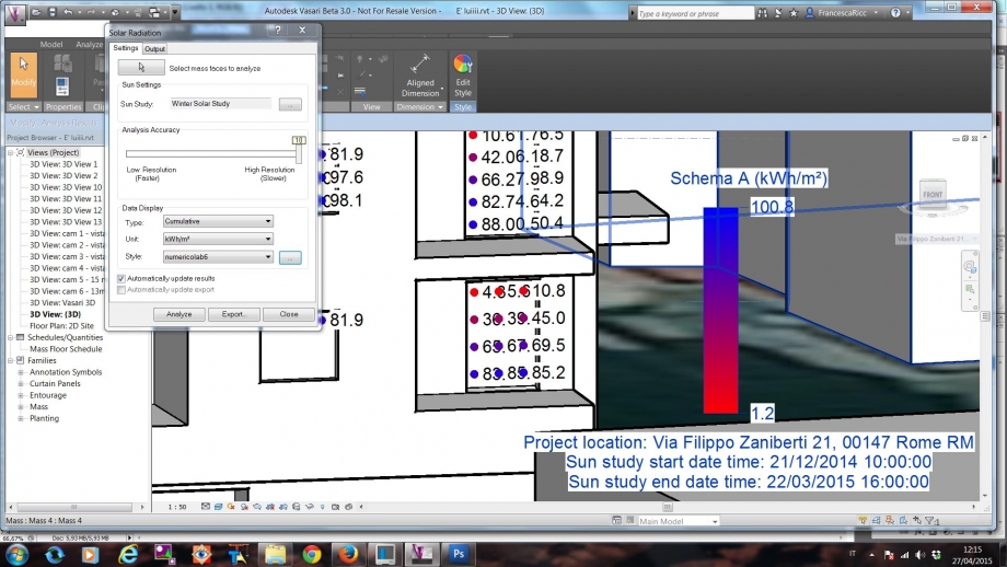
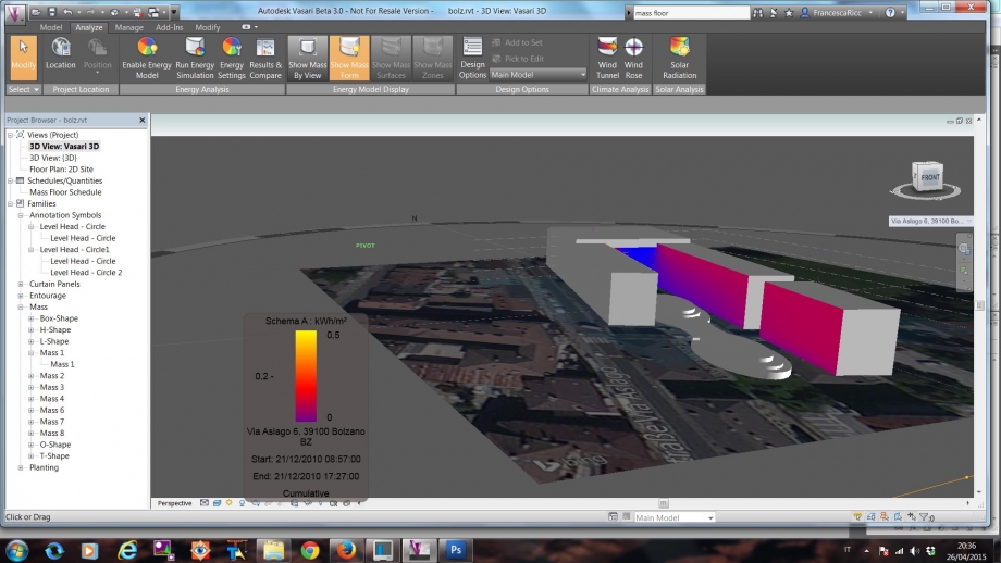
04_Applico lo stesso procedimento ed imposto Presets --> Winter Solar Study, per lo studio della radiazione solare in inverno.
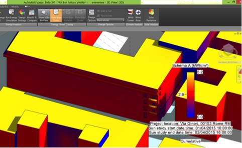
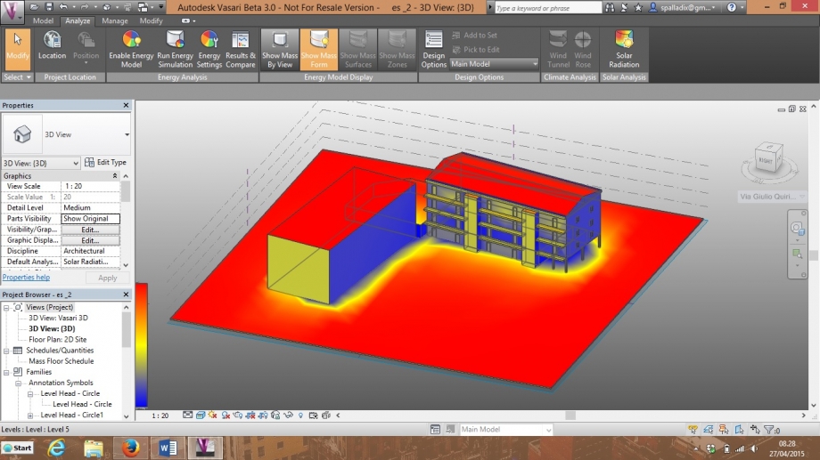
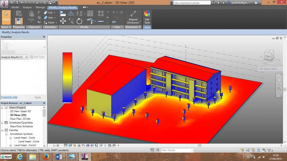
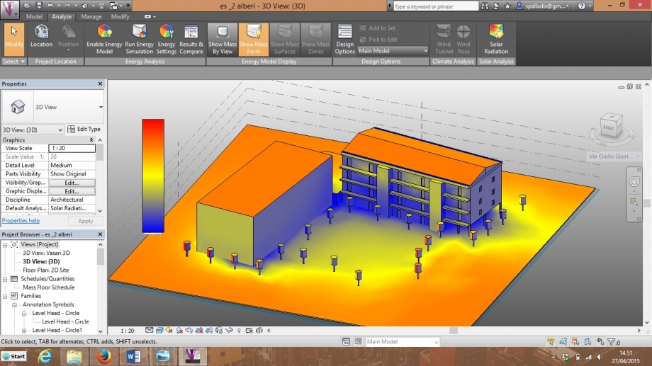
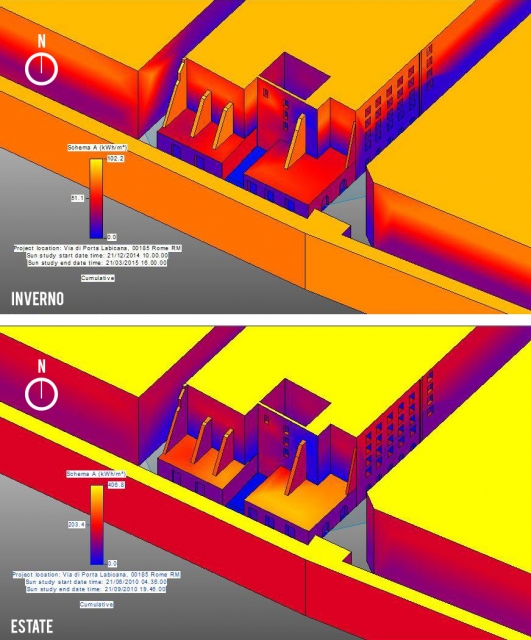
Vediamo quindi quanto calore è generato sulle facciate dell'edificio nel periodo estivo ed invernale.
Estate
Inverno
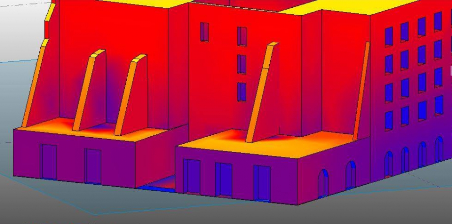
Nell’analisi solare vediamo come la facciata sud-ovest (lato lungo) sia riscaldata molto di più in inverno che in estate. Questo avviene a causa della minore inclinazione dei raggi solari in inverno rispetto a quelli in estate. Questo fatto ci ha stupiti in quanto, nonostante il maggior apporto di calore in estate, la facciata esposta a sud-ovest risulti più calda in inverno. Non essendo presenti però schermature orizzontali, il calore all’interno dell’edificio è percepito maggiormente in estate.
Per quanto riguarda la facciata nord-ovest (lato corto) non ci siamo stupiti del risultato sia in estate che in inverno, non avendo un irraggiamento diretto. Inoltre la presenza di un balcone su questo prospetto, non influisce nella schermatura parziale delle finestre sottostanti, ma anzi potrebbe contribuire maggiormente alla formazione di muffe.
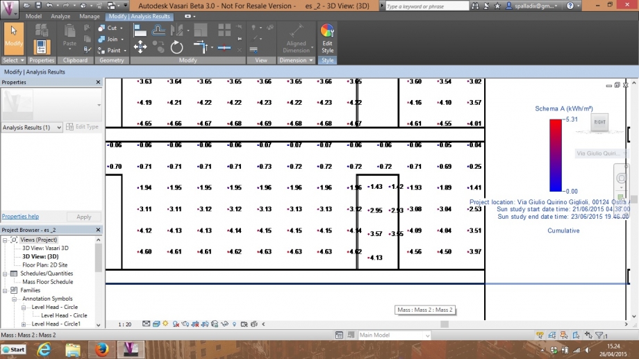
ANALISI SOLARE PER PUNTI
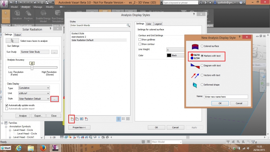
Completiamo l'analisi solare del nostro edificio facendo un uletriore studio sulle singole bucature con il comando Markers with Text.
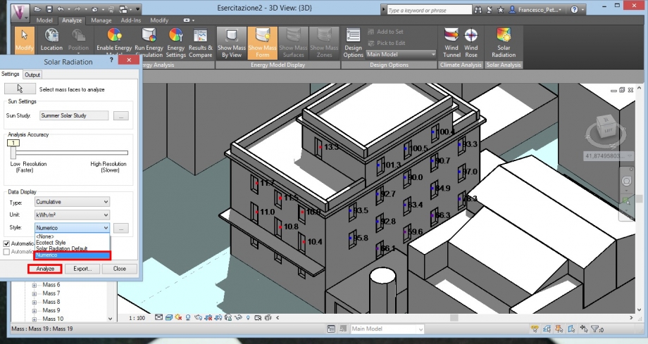
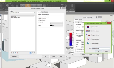
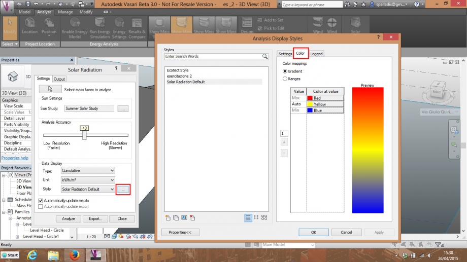
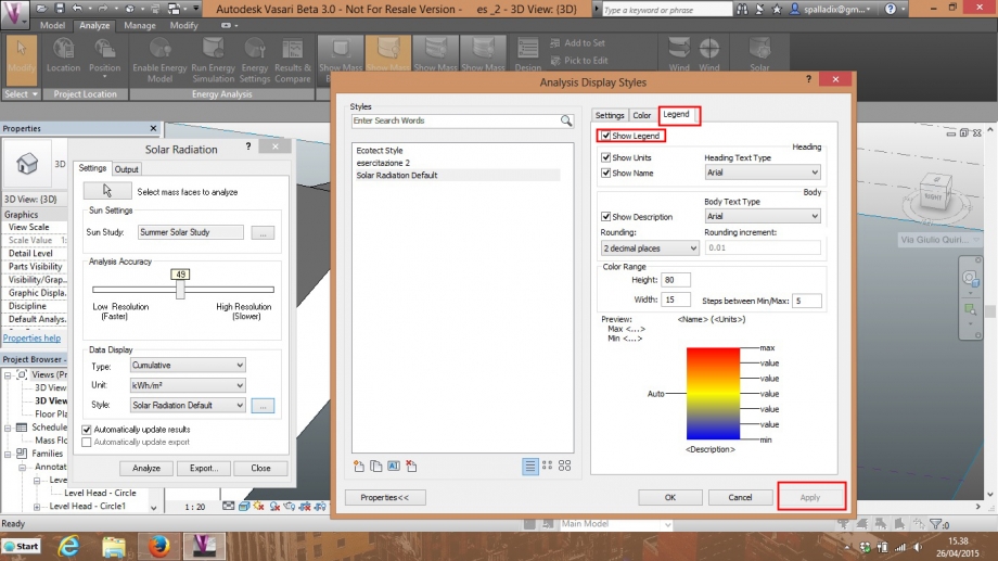
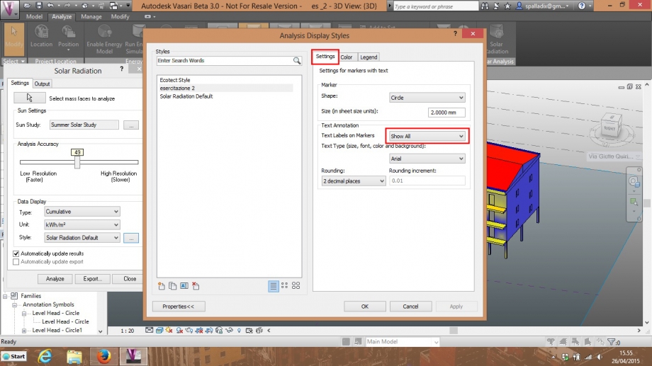
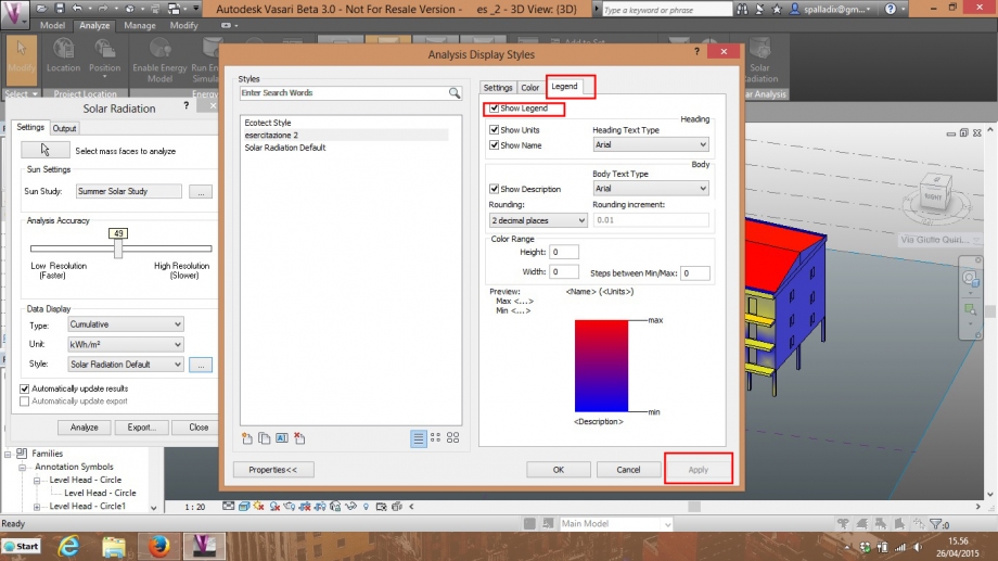
Analyze --> SOLAR RADIATION --> Style --> [...]
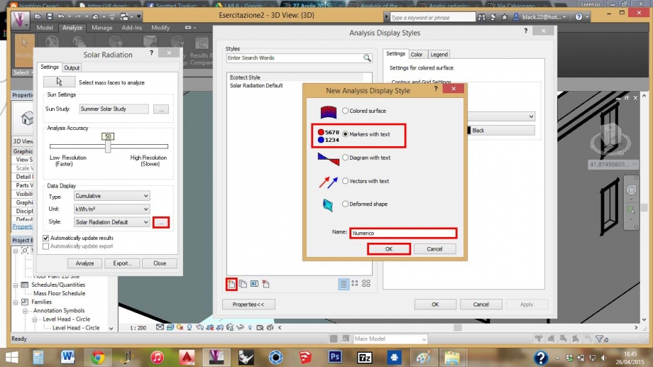
Si aprirà la finestra Analysis Display Style.
Cliccando sul comando "Nuovo" in basso a sinistra, creo un nuovo Stile spuntando Markers with text e dandogli un nome (Numerico)
Clicco su OK
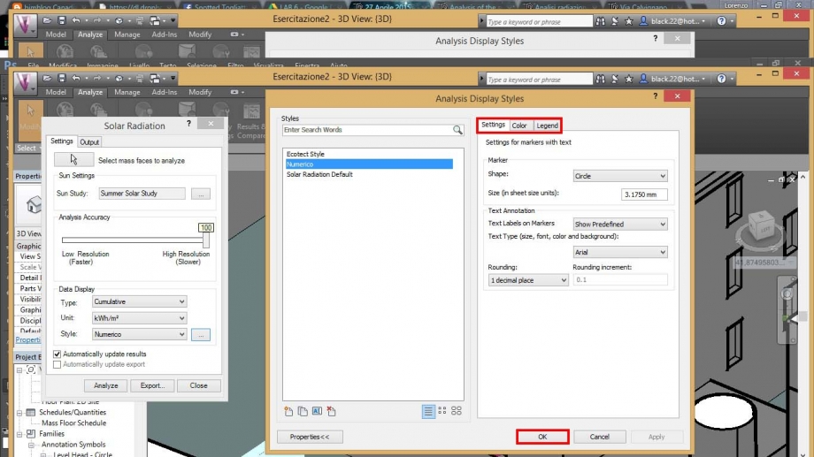
Quindi nella finestra Analysis Display Styles apparirà il nuovo stile creato. Selezionandolo posso modificare le impostazioni nella parte destra della finestra.
Clicco su OK.
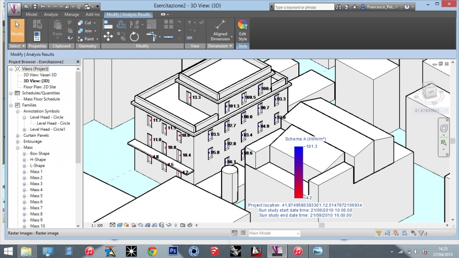
Imposto il nuovo stile (Numerico) nella finestra Solar Radiation e clicco su Analyze, dopo aver selezionato i singoli piani delle bucature.
Per impostare la giusta scala di risoluzione dei valori numerici dell'analisi per punti, modifico l'accuratezza dell'analisi impostandola a 1
Analysis Accuracy --> 1
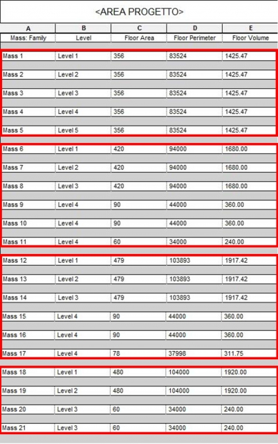
PUNTO 2 - Analisi dell'area di progetto_Via Aslago_Bolzano
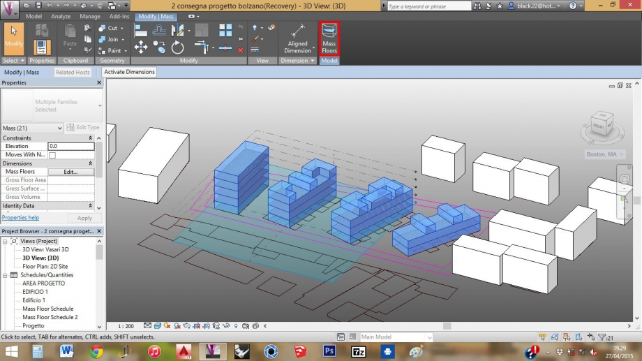
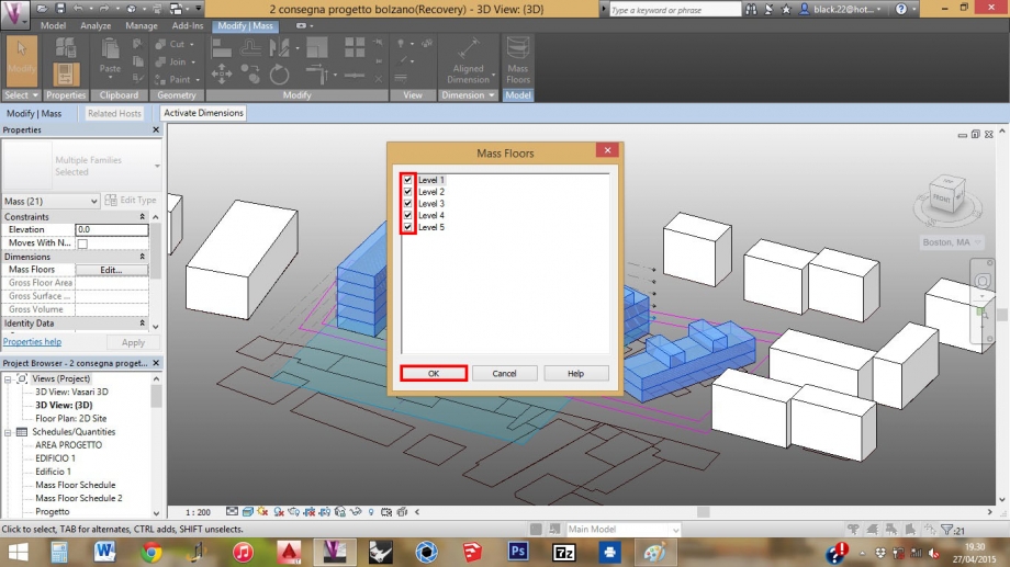
01_Dopo la divisione dei nostri edifici in 4 livelli, seleziono tutti i livelli degli edifici ed attraverso il comando MASS FLOORS spunto tutti i livelli
02_Clicco su Manage --> Schedules --> Schedules/quantities per creare una nuova schedule
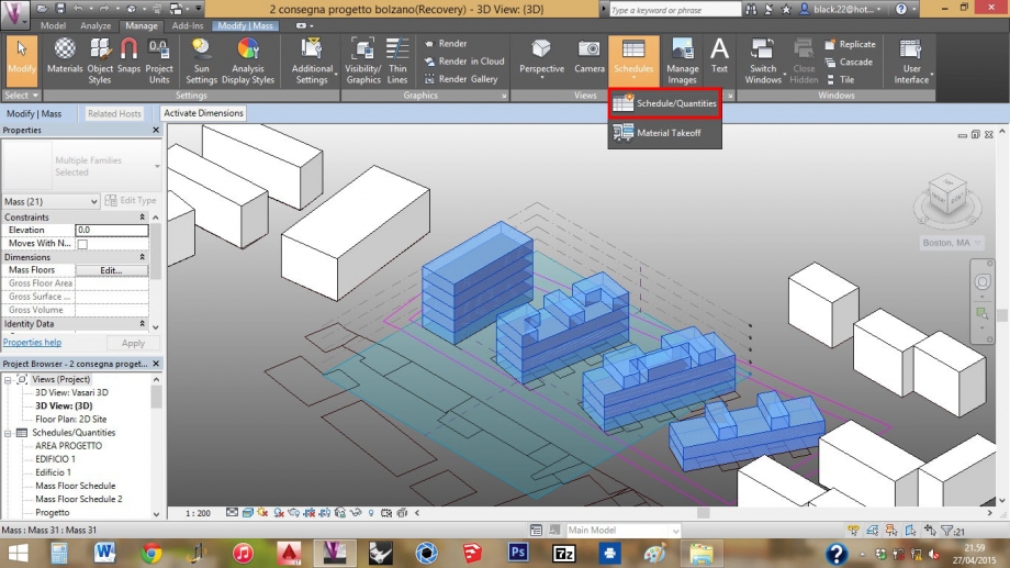
03_Nella finestra New Schedule clicco su "Mass floor" nel menù Category di sinistra ed assegno un nome "Area di progetto" nell'impostazione Name.
Clicco OK.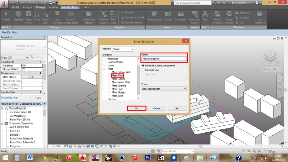
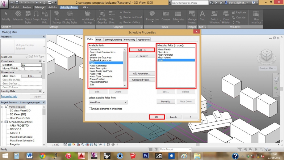
04_Si aprirà la finestra "Schedule Properties" e nell'impostazione Available Fields aggiungo col tasto "Add -->" :
-Mass: Family
-Floor Area
-Floor Perimeter
-Floor Volume
-Level
che appariranno nel menù di destra "Scheduled Fields".
05_Prima di cliccare OK, sempre nella finestra "Schedule Properties" vado sulla pagina "Sorting/Grouping".
Nel menù a tendina "Sort by" clicco su Mass: Family
Spunto "Footer" e nel menù a tendina accanto, clicco su "Totals only"
Poi spunto "Grand Totals" e neò menù a tendina accanto clicco su "Totals only"
Clicco OK.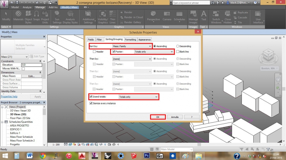
Abbiamo quindi ottenuto la Schedule con le informazioni riguardanti i nostri quattro edifici.
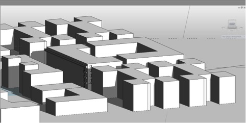
Le schedules degli edifici sono ordinate da sinistra (Mass 1, 2, 3, 4, 5) a destra (Mass 18, 19, 20, 21) nel Planivolumetrico.
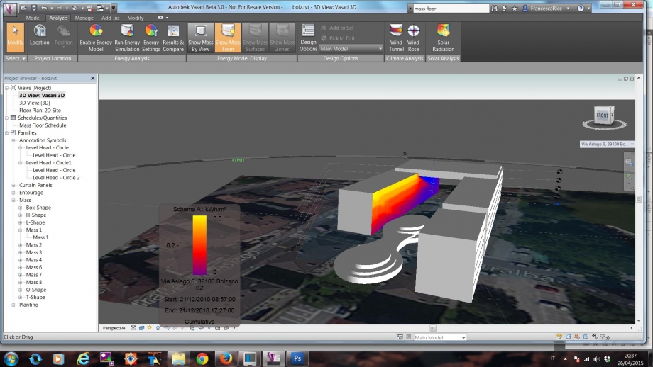
Analsi delle ombre della prima proposta di progetto - Regime Estivo
Analisi delle ombre della prima proposta di progetto - Regime Invernale
Il nostro progetto si articola in quattro edifici che hanno diverse altezze, diventando sempre più bassi andando verso la parte sud del lotto.
La disposizione dei nostri edifici è a ventaglio con tipologia a ballatoio. L’orientamento a sud-est consente un buon irraggiamento delle facciate nelle diverse ore del giorno.
Lun, 27/04/2015 - 17:18
 erica parrino
Lun, 27/04/2015 - 16:31
erica parrino
Lun, 27/04/2015 - 16:31
Per evolvere il modello creato in precedenza nell’esercitazione n.1, possiamo aggiungere al nostro solido volumetrico , con analoghi passaggi elementi come balconi, finestre, porte .Attraverso queste piccole modifiche possiamo visualizzare dei dettagli importanti come irraggiamento e radiazione solare. Per l’appunto nell'analisi della radiazione solare partendo da una scala più dettagliata la presenza o meno di un aggetto possono sicuramente cambiare le condizioni abitative dell’edificio e quindi in dettaglio la vivibilità o meno di una stanza.
1. La Modellazione
Partendo dall’ultima modellazione del nostro edificio , aggiungiamo delle nuove masse e\o vuoti che si andranno ad unire con quella restante precendemente costruita con l’esercitazione passata.
Possiamo scegliere il piano sul quale voler lavorare in questo modo.
Ora possiamo procedere con l’aggiunta di nuove masse, inserendo le misure in larghezza e lunghezza per avere quanto più possibili immagini simili al reale.
Adesso abbiamo creato un modello perfettamente corrispondente al reale, possiamo procedere con le ulteriori analisi.
2. Solar Radiation
A questo determinato punto possiamo iniziare con l’analisi solare e analizzare un lasso di tempo più lungo e non solamente un singolo momento della giornata.
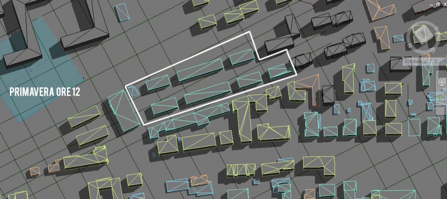
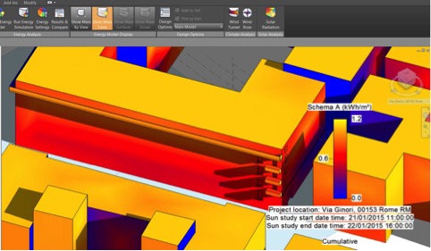
Vediamo qui lo studio del solstizio di primavera alle ore 11.00
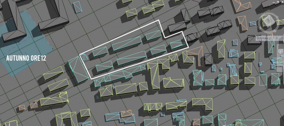
Qui vediamo invece il solsistizio d’inverno sempre alle ore 11.00
Per quanto riguarda l’analisi solare possiamo avere una differente visualizzazione ovvero attraverso i medesimi colori ma con una numerazione . I procedimenti sono gli stessi a quelli che facciamo per la normale radiazione .
All’interno della nostra analisi, considerate maggiormente le stagionali primaverili e invernali notiamo connotati estremamente differenti. Per esempio in inverno i balconi, dunque gli aggetti della facciata fanno molta ombra a quelli dei piani sottostanti andando a creare quindi molti dei coni d’ombra che potrebbero essere deleterei in materia costruttiva, potrebbero evolversi dunque questi problemi in degrado materico . Nello screenshoot della fase primaverile vediamo come invece nella medesima facciata gli aggetti non creano molta ombra ma l’intera facciata è in penombra a causa del grande edificio che vi è difronte.
Lun, 27/04/2015 - 16:53 Trombetti Carlotta
Lun, 27/04/2015 - 16:23
Trombetti Carlotta
Lun, 27/04/2015 - 16:23
http://bim.rootiers.it/node/609
Dopo aver inserito la vegetazione rilevante ai fini di un'analisi solare, studio l'ombreggiamento al tramonto, e ne traccio la sagoma a terra.
 Zone prese in analisi.
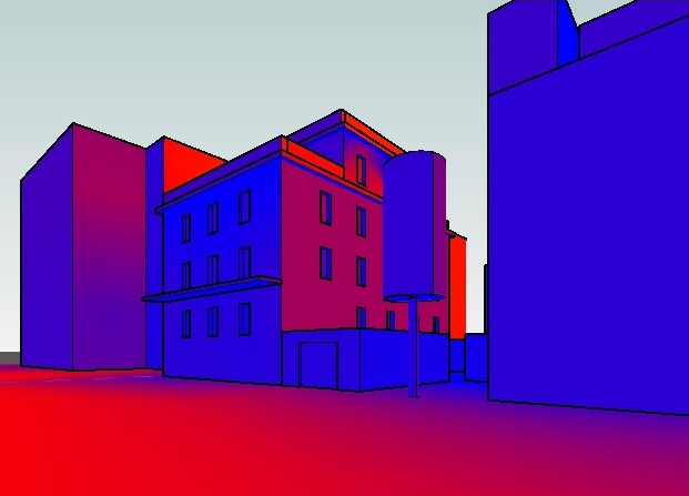
Abbiamo scelto di prendere come oggetto di analisi le zone che ci sembravano più rilevanti ai fini di un'analisi solare, come le logge e la facciata a nord dell'edificio, la quale risulta essere spesso in ombra.
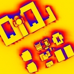
 Analisi estiva logge: valutazione degli spazi aperti con modalità analisi comulativa stagionale a colori.
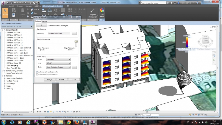
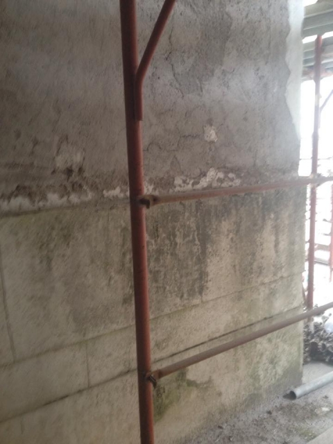
Analisi facciata nord: questa zona dell'edificio poco soleggiata presenta segni di degrado come muffe e presenza di muschio. Risulta dunque poco piacevole da guardare.
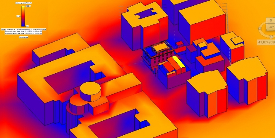
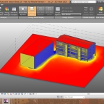
Analisi suolo.
Valutazione del suolo con modalità di analisi comulativa stagionale a colori.
Analisi della radiazione solare nelle finestre presenti nella loggia con modalità numerica.
Progetto a Bolzano

 lucia_mizzon
Lun, 27/04/2015 - 14:59
lucia_mizzon
Lun, 27/04/2015 - 14:59
Per potere capire al meglio l’azione della radiazione solare sull’edificio in analisi, dobbiamo riportare sul volume da noi precedentemente realizzato, i vari balconi, bucature o aggetti che possano influire sulla quantità di calore che colpirà le facciate nel corso dell’anno.
Per fare ciò prendiamo la volumetria dell’esercitazione precedente e la andiamo a modificare. Selezioniamo i volumi poi clicchiamo su EDIT IN-PLACE e disegnamo la forma per creare bucature o aggetti. Dopodiche clicchiamo su CREATE FORM e poi su SOLID FORM se si vuole creare un aggetto, o su VOID FORM se si vuole creare una bucatura.
Con questi comandi possiamo completare la realizzazione del nostro edificio con tutti i vari aggetti e bucature e poi proseguire con l’analisi della radiazione solare.
A questo punto proseguiamo con la radiazione solare. Clicchiamo su ANALYZE poi su SOLAR RADIATION e impostiamo tutti i parametri relativi al periodo in cui vogliamo analizzare la radiazione solare.
Poi Modifichiamo l’unità di misura e diciamo al software di analizzare tutte le facciate dell’edificio cliccando su ANALYZE.
Invece se vogliamo creare un nuovo stile di visualizzazione numerica andiamo sul comando SOLAR RADIATION e creiamo un nuovo stile che abbia la caratteristica MARKERS WITH TEXT
Dopo aver impostato lo stile di visualizzazione selezioniamo le facciate su cui svolgere l’analisi della radiazione solare e clichiamo su ANALYZE.
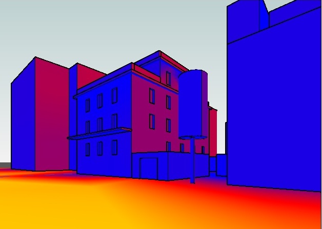
ANALISI DELLA RADIAZIONE SOLARE ESTIVA
ANALISI DELLA RADIAZIONE SOLARE INVERNALE
Dal risultato della radiazione solare invernale e estiva, possiamo evincere che i balconi e le logge vanno a limitare molto l’impatto solare sulla facciata che da’ sulla piazza, sia d’estate che d’inverno, andando a migliorare il confort abitativo all’interno nel periodo estivo, ma bensì d’inverno limita eccessivamente l’apporto di calore e di luce naturale nell’edificio. Si comprende quindi come la profondità degli aggetti non sia stata adeguatamente studiata al fine di ottimizzare al meglio questi valori.
Per quanto riguarda la piazza si nota come d’estate nelle ore centrali la piazza sia eccessivamente irraggiata, anche perchè la vegetazione esistente non è ancora sufficientemente in grado ombreggiare al meglio gli spazi di interazione sociale.
In Più si constata che un palazzo che dovrebbe dare sulla piazza è ancora in fase di costruzione. Consideriamo quindi anche il fatto che la radiazione solare verrà modificata dall’apporto di ombra causato da esso.
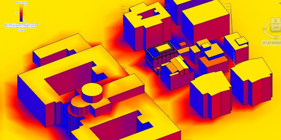
LOTTO DI PROGETTO: ANALSI RADIAZIONE SOLARE ESTIVA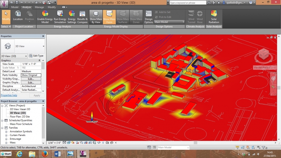
LOTTO DI PROGETTO: ANALSI RADIAZIONE SOLARE INVERNALE

Dall’analisi della radiazione solare del lotto di progetto, sito in via del porto fluviale, nel quartiere Ostiense a Roma, notiamo come la densità di volumi sia non così elevata, garantendo quindi così un’irraggiamento omogeneo e diretto in quasi tutto il lotto.
Vi fa eccezione solo la parte sud-est che, essendo contigua ad altri edifici, è maggiormente ombreggiate, e questo avviene soprattutto nel periodo invernale, quando il sole è abbastanza basso.
Lun, 27/04/2015 - 16:24
 Mattioli_Ottaviani
Lun, 27/04/2015 - 23:43
Mattioli_Ottaviani
Lun, 27/04/2015 - 23:43
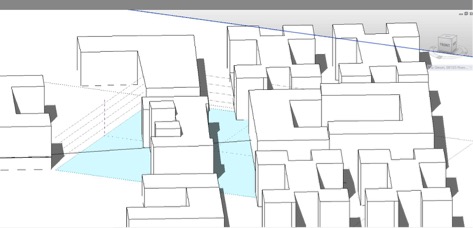
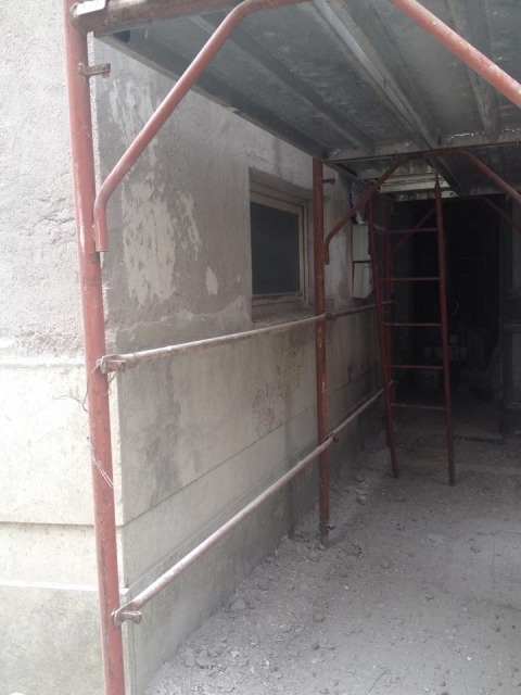
Per la precedente consegna abbiamo studiato il soleggiamento dell'edificio in via di Porta Labicana, concentrandoci sull'eventualità che la parte demolita venga ricostruita.
Passiamo ora ad uno studio più dettagliato della radiazione solare incidente su di esso. Per fare ciò arricchiamo il modello con i vuoti (delle finestre e delle porte) e i contrafforti che sono stati aggiunti in seguito al crollo, per garantire una maggior stabilità strutturale.
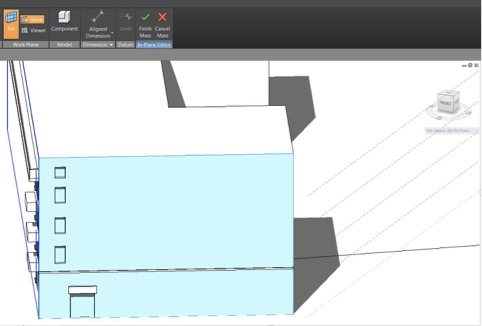
Procediamo con la realizzazione dei vuoti:
1 - per prima cosa selezioniamo l'edificio e clicchiamo sul comando "Edit in place" per modificarlo
2 - clicchiamo su "Set" e quindi selezioniamo il piano su cui vogliamo lavorare
3 - a questo punto con il comando "line" disegniamo il perimetro dei vuoti (per le porte abbiamo disegnato un arco e con il comando "join" lo abbiamo unito ai due segmenti verticali)
4 - selezioniamo il comando "create form" quindi "void form" per creare il vuoto
5 - inseriamo il valore numerico della profondità del vuoto
6 - per finire l'operazione clicchiamo su "finish mass"
Procedimento analogo per la realizzazione dei contrafforti, ma al punto 4 dobbiamo selezionare "solid form"
STUDIO DELLA RADIAZIONE SOLARE
1 - Da "Analyze" selezioniamo il comando "Solar Radiation". Si aprirà una finestra per l'impostazione dei vari parametri. Da qui è possibile aprire un'altra finestra per i "Sun Settings"
2 - Impostiamo i valori per l'analisi della radiazione solare
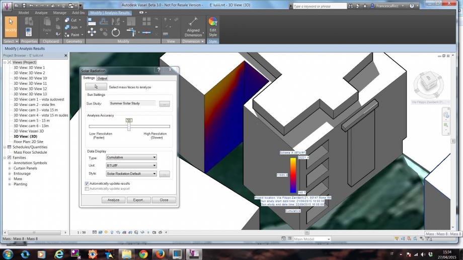
RISULTATO
In queste due immagini viene riportato l'impatto che la radiazione solare (quindi la luce) ha sull'edificio, da non confondere con l'energia termica (calore). D'inverno il tetto risulta arancione, un colore più "tenue" rispetto al giallo che caratterizza il tetto d'estate, perchè in questo periodo l'inlcinazione dei raggi del sole è di circa 30° (mentre in estate è di 70°). Le parti di edificio colorate in blu sono quelle più fredde ed umide (d'inverno) e si trovano nella parte bassa sulle facciate a sud est e sud ovest (ad eccezione della porzione all'imbocco della via, che risulta invece di un colore tendente all'arancione). Nell'insieme l'edificio non presenta dei buoni valori, non solo per via del suo orientamento ma soprattutto per la vicinanza degli edifici circostanti. La sua costruzione risale agli anni 30, periodo in cui ancora non si aveva una certa sensibilità nei confronti delle norme urbanistiche e delle distanze minime da tenere tra gli edifici. Infatti la facciata a nord, oltre ad essere svantaggiata dal punto di vista dell'esposizione, si trova ad una distanza ravvicinata rispetto all'edificio adiacente. Dall'immagine è possibile vedere come l'area sia blu.
studio della radiazione solare complessivo di tutto l'anno
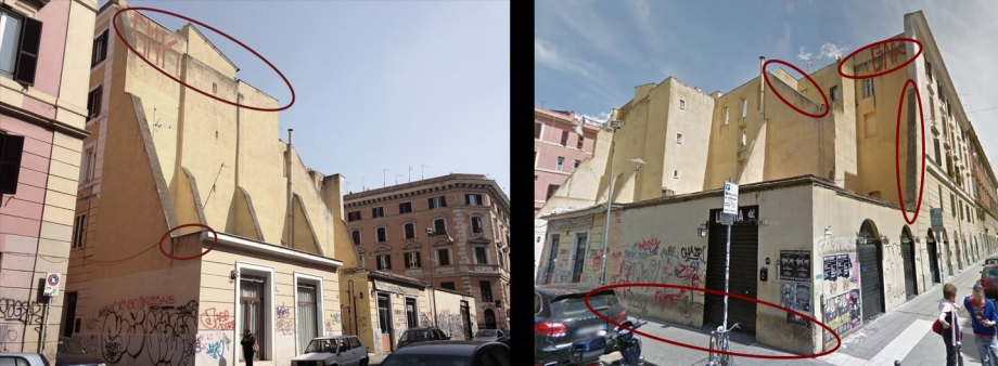
Ci sono delle incongruenze tra l'effettivo degrado della facciata e l'analisi della radiazione solare effettuata. In modo particolare la superficie dei contrafforti risulta danneggiata molto probabilmente perchè esposta alla pioggia, non avendo nessun tipo di impermeabilizzazione. Stesso discorso per la parte superiore della facciata, priva di cornicione e quindi anch'essa soggetta all'azione della pioggia e alle conseguenti infiltrazioni d'acqua. Nella parte bassa a destra invece risulta assente un elemento di protezione che è al contrario presente nella parte a sinistra, Questa mancanza porta a degli effetti di danneggiamento della parete muraria.
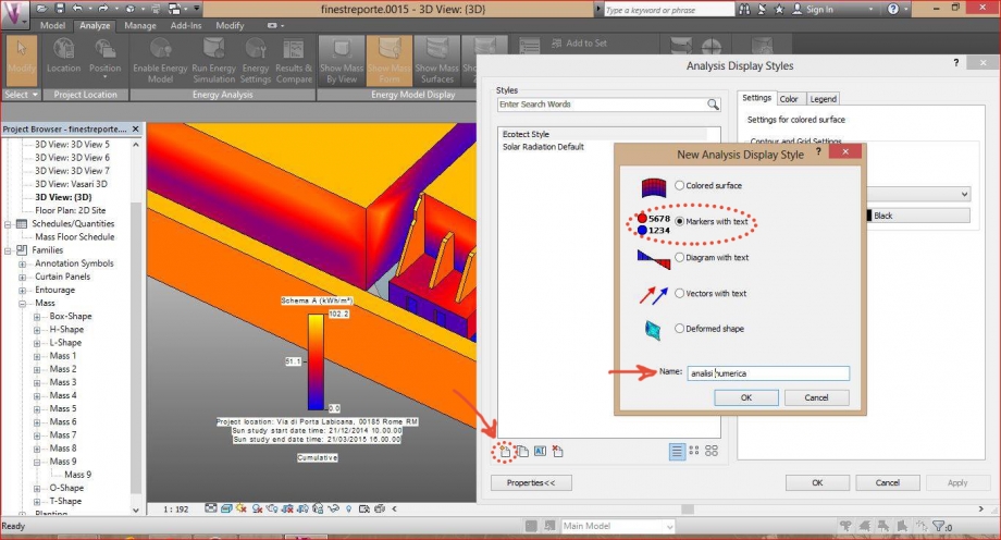
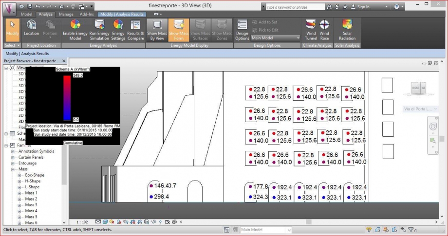
ANALISI NUMERICA
Possiamo ottenere un'analisi più accurata cambiando lo stile di visualizzazione, invece di "colored surface" passiamo a "markers with text". Dalla finestra "Analysis Display Style" clicchiamo sull'icona in basso a sinistra e si aprirà una nuova finestra. Da qui spuntiamo "Markers with text" e cambiamo il nome del nuovo stile.
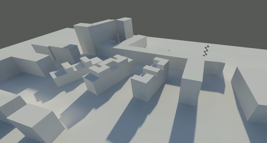
AREA DI PROGETTO_STUDIO SOLEGGIAMENTO
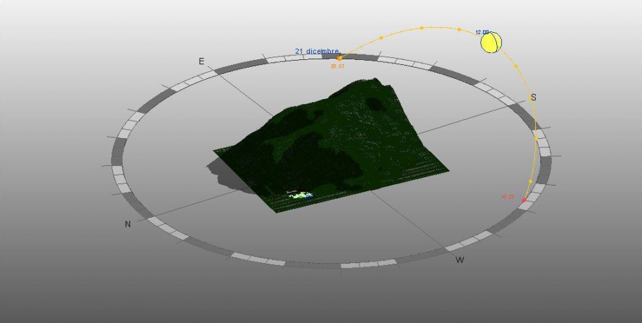
Dall'analisi dell'ombreggiamento del lotto di progetto è evidente quanto la montagna rappresenti un problema per gli edifici che si vanno a insediare in quella zona. Basti pensare che in inverno l'area rimane in ombra fino alle 11 del mattino circa.
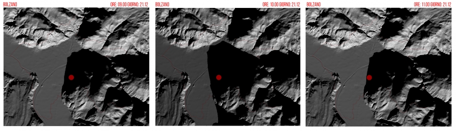
Per ovviare a questo problema non vi sono molte possibilità ma tra queste si può optare per una migliore esposizione degli edifici che attualmente manca in quanto le facciate più estese sono poste con andamento est ovest
Analisi dell'ombreggiamento allo stato di fatto: