


 marrone_maresca
Lun, 27/04/2015 - 21:50
marrone_maresca
Lun, 27/04/2015 - 21:50
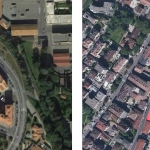
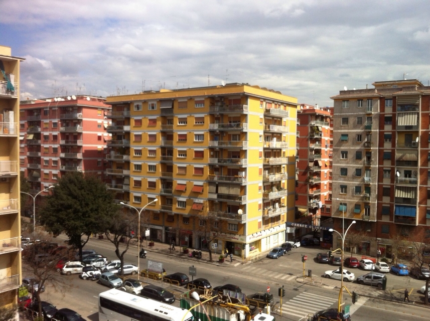
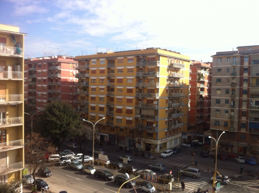
Via Taurasia 9, quartiere San Giovanni
Nella scorsa consegna abbiamo analizzato un edificio in zona San Giovanni in forme molto volumetriche ed elementari. Con questa consegna invece ci avviciniamo ad uno studio più dettagliato e preciso, aggiungendo aggetti, bucature delle finestre ed altri elementi della facciata, affinchè tramite Vasari, si possa ottenere uno studio preciso del soleggiamento durante i vari periodi dell’ anno ed un’ analisi delle radiazioni solari. Abbiamo quindi scelto di studiare la facciata esposta a sud affinchè possa essere evidenziata maggiormente l’ esposizione solare.
Procedimento
1. Inizio dal volume creato precedentemente (modify mass>edit in place)
2. Posso adesso modificare e aggiungere elementi (model>line/rectangle/circle>create form>solid form/void form>finish mass). Per creare i balconi a partire dalla facciata, abbiamo usato il comando "set work plane" che definisce il piano su cui lavorare.
3. Cominciamo la procedura per analizzare la radiazione solare (analyze>solar radiation)
4. Selezioniamo le superifici da analizzare (select mass faces to analyze)
5. Impostiamo i valori del sole (sun study>multi day>summer/winter solar study>set date/time)
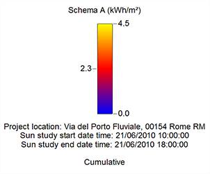
6. Decidiamo il metodo con cui visualizzare i dati (type>cumulative) (unit>kWh/m2) (style>solar radiation default>color>max value "red"/min value "blue")
Analisi della radiazione solare
Si comincia con un’ analisi dell’ edificio e del contesto in base alle diverse stagioni. Abbiamo utilizzato, come di consueto, i colori blu giallo e rosso, il blu per le temperature più fredde, il giallo per quelle intermedie ed il rosso per le più calde. L'analisi mostra l’ irraggiamento, che si misura in kWh/m2. Nelle quattro immagini sottostanti vediamo l'irraggiamento del nostro edificio in inverno, primavera, estate ed autunno. C’ è però da ricordare che i colori non rappresentano sempre le stesse temperature nelle diverse stagioni dell’ anno.

Primavera

Estate

Autunno

Inverno
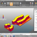
ANALISI NUMERICA DI DETTAGLIO
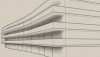
Qui abbiamo selezionato le bucature e si vede il graduale aumento di irraggiamento solare dai piani più bassi a quelli più alti. Si può notare il maggiore irraggiamento nelle bucature orizzontali.
Possiamo notare le differenze seguendo quest’ ordine delle stagioni: estate, autunno, inverno e primavera.

Primavera

Estate

Autunno

Inverno
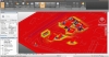
ANALISI RADIAZIONE DEL TERRENO
Infine abbiamo compiuto uno studio riguardante la radiazione del terreno da parte del sole nelle diverse stagioni dell’anno con il seguente ordine: primavera, estate, autunno, inverno.

Primavera

Estate

Autunno

Inverno
CONCLUSIONI
In conclusione abbiamo notato come la facciata sud sia ben soleggiata in tutte le stagioni con alcune differenze tra i primi e gli ultimi piani della facciata. In inverno infatti notiamo come siano meglio esposti i piani superiori, mentre come in primavera il soleggiamento sia più uniforme. Infine nei periodi estivo ed autunnale la facciata sud sia ben ombreggiata in modo uniforme.
La radiazione solare è ben distribuita sulla facciata, con delle differenze a seconda degli aggetti o delle rientranze che in estate contribuiscono sostanzialmente ad abbassare il valore dell'irraggiamento, mentre in inverno non influenzano particolarmente.
Lun, 27/04/2015 - 22:17
 pomponi_sauzzi
Lun, 27/04/2015 - 20:27
pomponi_sauzzi
Lun, 27/04/2015 - 20:27
Analisi della radiazione solare via dei Lecci Bracciano
per poter analizzare al meglio l'influenza della radiazione solare su tutto l'edificio è necessario inserire nel volume di base, usato per la prima esercitazione, i vari balconi, bucature e aggetti che vanno ad influenzare lo studio.
- Per fare ciò basta selezionare il volume di base cliccando poi su EDIT IN -PLACE e selezionando con SET la facciata dove lavorare, disegnare poi il profilo dell'oggetto da creare e usando o il comando SOLID FORM o il comando VOID FORM creare il solido o il vuoto.

Per eseguire un approfondita analisi della radiazione solare su tutte le parti dell' edificio è necessario regolare le impostazioni di base del comando SOLAR RADIATION, questo ci consentirà di avere uno studio più specifico e dettagliato.
-come prima cosa aprire il menù ANALYZE e cliccare sul comando SOLAR RADIETION;

-modificare l'unità di misura in Kwh/mq
- creare un nuovo stile di analisi

-scegliere il tipo di analisi che si vuole eseguire sull'oggetto e rinominare il nuovo stile

- scegliere il grado di accuratezza dell'analisi
-selezionare gli ogetti da analizzare

-selezionare lo spazio temporale da prendere in esame ed effettuare l'analisi

Studio delle superfici all'aperto

come si può notare tra estate e inverno le superfici che rimangono a KWh/mq =0 sono quasi invariate, queste zone sono quelle linitrofe agli edifici.
Questo scarzo irraggiamento solare potrebbe portare con il tempo a problemi con la parte inferiore degli edifici, ad oggi questi eventuali problemi non sono ancora presenti in quanto l'edificio oltre ad essere stato costruito da meno di dieci anni , ha nella parte bassa un rivestimento in pietra.

Studio delle superfici opache


Da queste analisi pi può notare che la parte alta dell' edificio presenta dei problemi d'irraggiamento dovuti dall'aggeto del tetto, questo eventuaale problema però non è visibile nello stato attuale dell'edificio.

Studio delle loggie

Per lo studio delle loggie di questo edificio abbiamo usato un analisi numerica più accurata e mirata a studiare i KWh/mq di ogni singolo punto della superficie , questo ci porta a notare come la loggia nel periodo invernale abbia un maggiore irraggiamento solare che nel periodo estivo questo è dovuto dal fatto che la profondità della loggia permette ai raggi invernali con un angolo inferiore di colpire la parete , che invece non viene colpita da quelli estivi con un angolo superiore.
Analisi del soleggiamento via Aslago Bolzano

La zona di progetto si trova nel quartiere Oltisarco-Aslago nella città di Bolzano.
Il clima della città, situata in un fondovalle alpino, risulta essere continentale, con minime invernali di norma sotto lo zero e massime estive anche oltre i 35 °C. D'estate fa molto caldo e in inverno abbastanza freddo, per colpa anche della posizione in una conca che impedisce il ricambio d'aria. L'area di progetto presenta una grande problematica che influenza molto lo studio del soleggiamento:la presenza del colle Kolhen ad est.
Solstizio d'estate ore 9:00

Solstizio d'estate ore 11:00

Solstizio d'inverno ore 9:00

Solstizio d'inverno ore 11:00

Quest'ultimo impedisce , nei mesi invernali, al sole di illuminare l'area fino alle 11 di mattina e quindi rende il soleggiamento difficoltoso.
Attualmente gli edifici hanno un orientamento est-ovest che secondo il nostro punto di vista non sfrutta al meglio la posizione per accogliere maggiormente la radiazione solare perciò nel progetto abbiamo modificato l'orientamento rendendolo nord-sud. In questo modo gli edifici, posti a distanza di 18 metri, non si fanno ombra a vicenda e creano una situazione di permeabilità dell'area.
Lun, 27/04/2015 - 22:02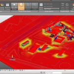 Esposito_France...
Lun, 27/04/2015 - 20:47
Esposito_France...
Lun, 27/04/2015 - 20:47
L' edificio da noi analizzato é situato in via le quadra a Castelliri, un paese della provincia di Frosinone .
Per potere capire al meglio l’azione della radiazione solare sull’edificio in analisi, dobbiamo riportare sul volume dello stesso , i vari balconi, bucature o aggetti che possano influire sulla quantità di calore che colpirà le facciate nel corso dell’anno.
Andremo ad analizzare questo aspetto attraverso il plug-in Solar Radiation che ci permette di analizzare le radiazioni solari sugli edifici di un intorno che si vuole studiare. Grazie a questo strumento ci è permesso di valutare quali punti sono più colpiti dall'irraggiamento e quali invece sono soggetti a fenomeni di umidità e quindi alterazione perchè difficilmente raggiunti dai raggi solari. Ad influenzare principalmente questi effetti sono le ombre che generano gli edifici stessi, la capacità riflettente delle superfici, le sporgenze quali cornicioni e balconi o le rientranze quali logge e finestre.
Una volta modellati gli edifici e gli elementi tridimensionali delle facciate, possiamo proseguire con l'analisi.
1) Analisi relativa al solstizio d'inverno.

2) Analisi relativa al periodo invernale.

3) Analisi relativa al solstizio d'estate

4) Analisi relativa al periodo estivo

Dall'analisi si evince che la casa é molto esposta alle radiazioni solari ,in quanto la stessa si trovi in una zona poco edificata .
Tuttavia possiamo riscontrare che alcune parti della casa,difficilmente raggiunte dai raggi solari ,sono soggette ad umidità

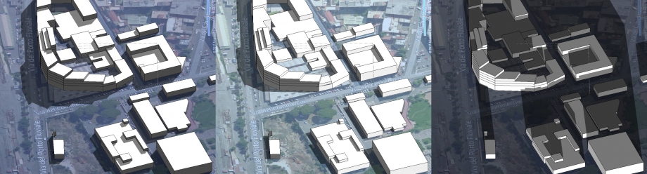
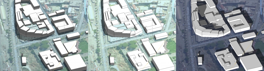
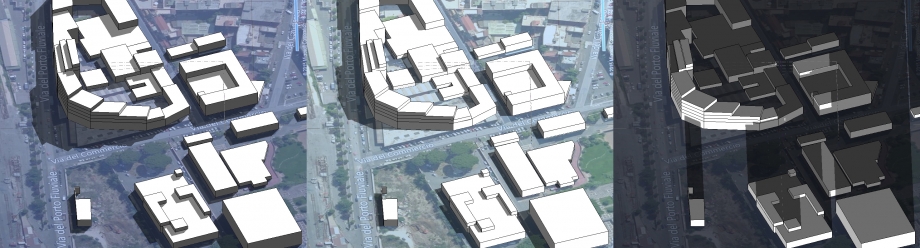
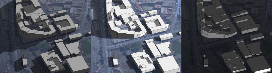
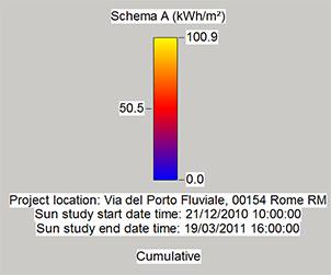
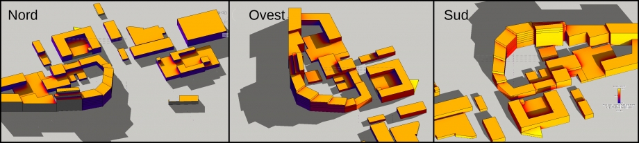
LOTTO DI PROGETTO (sito in via del porto fluviale, nel quartiere Ostiense a Roma)
1) Analisi relativa al periodo invernale

2) Analisi relativa al periodo estivo
Dall’analisi della radiazione solare del lotto di progetto notiamo come la densità di volumi sia non così elevata, garantendo quindi così un’irraggiamento omogeneo e diretto in quasi tutto il lotto.
Vi fa eccezione solo la parte sud-est che, essendo contigua ad altri edifici, è maggiormente ombreggiate, e questo avviene soprattutto nel periodo invernale, quando il sole è abbastanza basso.
Lun, 27/04/2015 - 21:49
 Navarro_Stosic
Lun, 27/04/2015 - 17:18
Navarro_Stosic
Lun, 27/04/2015 - 17:18
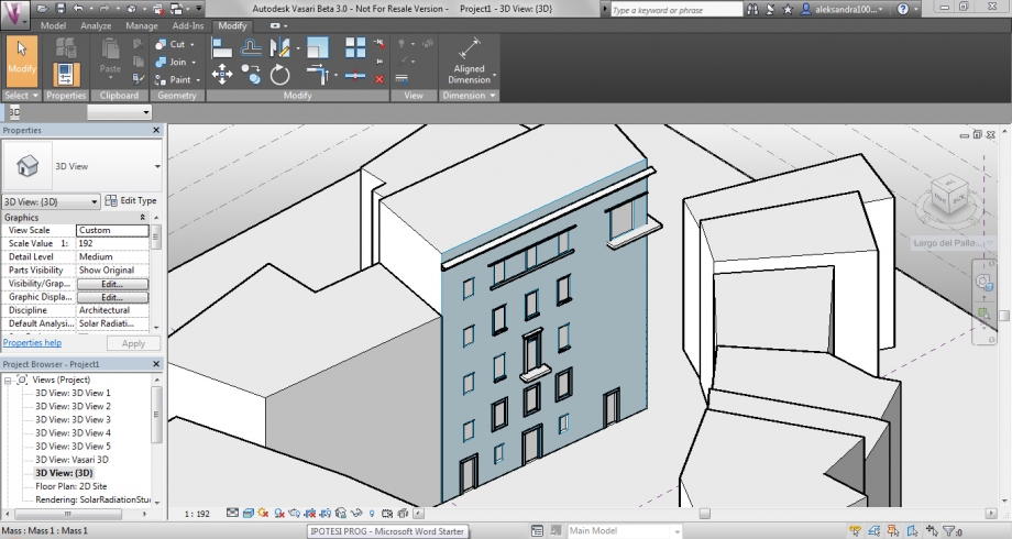
Analisi della radiazione solare - Largo del Pallaro 4 (RM)
Aggiungiamo ulteriori dettagli alla facciata dell’edificio della prima esercitazione: bucature, aggetti, balconi, cornicioni, ecc...
We added more details to the facade of the building from the first delivery: openings, projections, balconies, moldings, etc...
Procediamo con l’analisi solare del terreno, per comprendere quale siano le situazioni che si creano nella piazza antistante l’edificio.
La piazza è piccola e circondata da edifici su tutti i lati: questo causa una situazione sfavorevole nel periodo invernale, perchè i raggi solari che colpiscono la piazza sono scarsi ed il microclima che si crea nella zona è freddo, umido e poco piacevole; nel periodo estivo la chiusura e le zone d'ombra create dagli edifici sono un vantaggio e si trasformano in un luogo di riparo durante le giornate afose delle estati romane.
In questo spazio non sono presenti alberature in quanto è occupato per la maggior parte da un'area di parcheggio.
We proceed with the solar analysis of the ground, to understand what are the situations that happen in the square in front of the building.
The square is small and is surrounded by buildings on all sides: that causes a negative situation during winter, because sun beams that reach the square are very few and the microclimate that is generated is cold, wet and unpleasant; during summer the closure and the shaded areas generated by the buildings are an advantage and become a shelter during the muggy roman summers.
In this space there are no trees, since the main part of it is occupied by a parcking area.


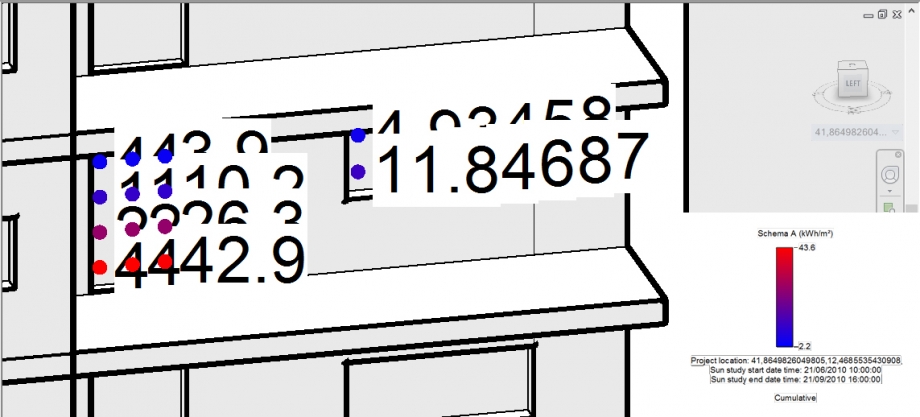
Passiamo all'analisi solare della facciata. In questo caso non usiamo più i gradienti per la lettura dei dati, ma ci serviamo dei markers (pallini, quadratini,...) accompagnati dal dato vero e proprio. Creiamo ed impostiamo lo stile "Markers with text" e poi selezioniamo la facciata dell'edificio che abbiamo preso in analisi.


Ipotesi progettuale - Via Aslago (BZ)


L'idea dietro la nostra prima ipotesi progettuale era quella di cercare di risolvere due dei problemi principali che presenta l'area di Bolzano, ovvero quello del soleggiamento e quello della ventilazione. Dovendo tenere in considerazione entrambe le problematiche contemporaneamente, è risultato subito chiaro che la classica disposizione dell'edifcio in direzione Est-Ovest avrebbe favorito sì il soleggiamento con maggiore apporto di radiazione solare, ma avrebbe anche sfavorito una buona ventilazione, perchè avrebbe fatto da scudo al già debole vento invernale proveniente da Nord-Est e a quello estivo proveniente da Sud. Cambiando la direzione della disposizione abbiamo anche diminuito l'area effettiva delle facciate esposte a Nord.
Siamo partite allora da dei moduli di 80 m2 di area ciascuno che ci permettono di avere un maggiore controllo dimensionale. I moduli formano due stecche (tagliate entrambe dalla strada che attraversa il lotto), che seguono la direzione dei venti per formare un "corridoio", e, spostando i moduli perpendicolarmente a questa direzione, definiamo meglio gli spazi. Abbiamo deciso di rastremare il "corridoio" agli estremi delle stecche e di allargarlo nel mezzo per formare una piazza.
The idea behind our first project proposal is to try to solve two of the main problems of the area of Bozen, which are the solar radiation and the ventilation. Since we had to keep in mind both of the problems at the same time, it was clear that the classical disposition of the building in the East-West direction would favor a good solar radiation, but it would also be a disadvantage for the ventilation, since it would act like a sort of shield against the already weak winter wind that comes from North-East and the summer winds that comes from South. Changing the direction of the disposition we also decreased the effective area of the facades facing North.
So we started from moduls, with an area of 80 m2 each, that allow us to have a better dimensional control. The moduls form two sticks (both cut by the road that crosses the site) that follow the direction of the winds to form a "corridor" and, moving the moduls perpendicularly to this direction, we are able to better define the spaces.
Analisi - Inizialmente abbiamo importato su Vasari il modello 3D creato precedentemente su Rhino, ma è stato molto difficile gestirlo, perchè a volte Vasari lo riconosce ed altre no, finendo in questi casi col crashare e col bloccare anche il display driver. Similmente abbiamo avuto problemi nell'importare la massa della montagna.
Analysis - Initialiy we imported in Vasari the 3D model that we created with Rhino, but it was very difficult to manage it, because sometimes Vasari recognises it and somethimes it doesn't, ending, in these cases, with crashing down and blocking also the display driver. Likewise we had problems while importing the file with the mountain.


A questo punto abbiamo ridisegnato l’edificio in 3D direttamente su Vasari e, una volta terminata la massa, abbiamo indicato i piani della massa (comando “Mass Floors”) per poi proseguire con l’analisi delle quantità e delle metrature (comando “Schedules/Quantities”).
At this point we designed again the building directly on Vasari and, once finished the mass, we indicated the floors (command "Mass Floors") and then moved to the analysis of the quantities and the measures (command "Schedules/Quantities”).

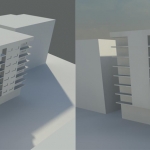
Procediamo con l'analisi della radiazione solare. Da un'analisi preliminare ci rendiamo subito conto che le facciate più fredde dell'edificio sia in inverno che in estate sono quelle esposte ad Ovest (perchè in realtà tendono leggermente verso Nord-Ovest).
Let's proceed with the analysis of the solar radiation. From a preliminar analysis we can immediately realise that the coldest facades of the building, during both winter and summer, are the ones exposed to West (beacuse actually they tend slightly to North-West).


Ci interessa però capire cosa succede all'interno tra le due stecche. Guardando il progetto in pianta, posizionando la vista dall’alto, osserviamo come la piazza che si trova tra le stecche riesce, bene o male, a ricevere radiazione solare sia durante le giornate estive che durante quelle invernali ed il frastagliamento delle facciate dato dallo slittamento dei moduli permette che ci siano sempre in diversi punti delle piccole zone d’ombra. Dal momento che il clima di Bolzano è un clima continentale (inverno freddo, estate calda), il sole estivo verrà schermato con delle alberature caducifoglie, che però in inverno, con la perdita delle foglie, filtreranno la radiazione solare fino alla piazza.
We want to understand what happens in between the two sticks. By looking the project in plane view, we can see how the little square that is in the space within the sticks receives more or less the solar radiation during summer days and winter days too and the jaggedness of the facades given by the slided moduls allows to have always some shaded spots in multiple zones. Since the Bozen's climate is a continental climate (cold winters, hot summers), the summer sun will be screened with deciduous trees, that in winter, with the loss of the leaves, will let through the solar radiation.


Abbiamo cercato di fare anche un'analisi del vento usando il comando "Wind Tunnel" per controllare l'effettiva permeabilità dell'aria nel lotto. Una volta inseriti i dati relativi a venti della Provincia di Bolzano (direzione, velocità convertita da km/h a m/s) ed aggiungendo alcune delle alberature esistenti nell'area, abbiamo visto che il corridoio presente tra i due edifici permette al vento di permeare liberamente.
We tried also to make a wind analysis using the command "Wind Tunnel", to control the effective permeability of the air in the site. Once we inserted the data relating to the winds in the Province of Bozen (drection, wind speed converted from km/h to m/s) and after adding some of the existing trees in the area, we saw that the corridor between the two buildings allows the wind to permeate freely.
 (situazione invernale con venti provenienti da Nord, Nord-Est)
(winter situation with winds coming from North, North-East)
 (situazione estiva con vento proveniente da Sud)
(summer situation with winds coming from South)
Lun, 27/04/2015 - 21:29
 Gualtieri_Merlin
Lun, 27/04/2015 - 19:57
Gualtieri_Merlin
Lun, 27/04/2015 - 19:57
Nella cornice di questo secondo esercizio, abbiamo conservato l'edificio dellla prima consegna perché ci sembrava interessante.
Tuttavia, per i problemi di accesso, abbiamo studiato solamente le facciate Nord-ovest e Sud-ovest.
Prima parte : Aggiungere dei dettagli sulle facciate
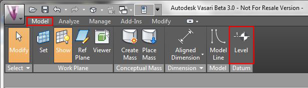
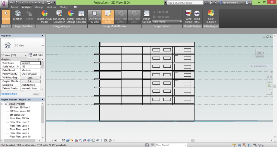
In questo esercizio, è più importante di lavorare coi livelli. Difatti, ogni livello rappresenta un piano, e poiché i balconi, logge, finestre e porte si trovano ad ogni piano, è più facile dei costruire aiutandosi dei livelli.
Per difetto Vasari contiene solamente 5 livelli. Su questo edificio abbiamo 9 livelli contando il tetto. Abbiamo aggiunto 4 livelli ogni a 3 metri dunque.
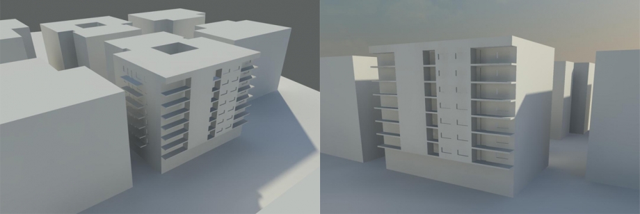
Vedremo poi che i balconi hanno un ruolo molto importante nell'impatto del sole sulle facciate, è importante di costruirli dunque.
Abbiamo ricreato semplicemente delle forme che abbiamo estruso poi alla buona dimensiona.
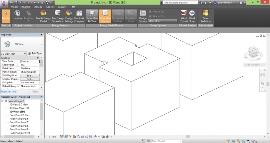
L'edificio simplice prima di avere costruito i balconi
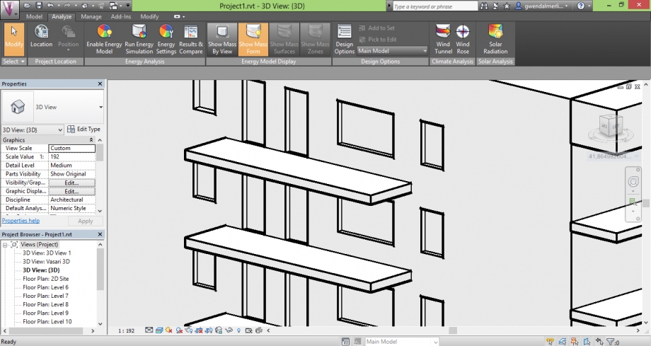 Un esempio dei balconi
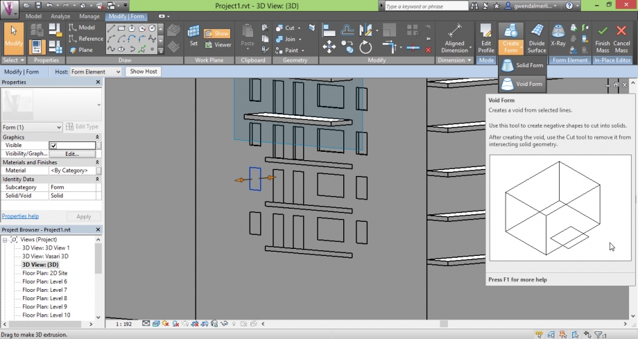
Abbiamo disegnato solamente una parte delle finestre di ogni facciata, per mostrare un esempio ad ogni volta.
Ancora una volta, ciò è molto semplice. Abbiamo creato semplicemente una forma che abbiamo trasformato in forma vuota per formare le finestre e porte.
Infine, è tanto importante di fare gli edifici intorni cui possono causare delle maschere sull'edificio che studiamo.
Seconda parte : Solar Radiation
Primo di tutto, dobbiame verificare che la localizzazione è buona. Quest'edificio è situato Via Marconi, nel Sud di Roma.
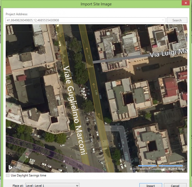
Adesso possiamo iniziare à confgurare il « Solar Radiation » che si trova nella parte « analizia ».
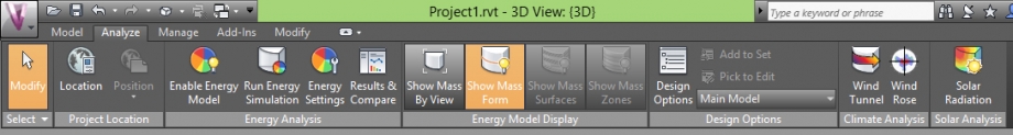
Innanzitutto bisogna selezionare le facciate che vogliamo studiare grazie al bottone con un cursore
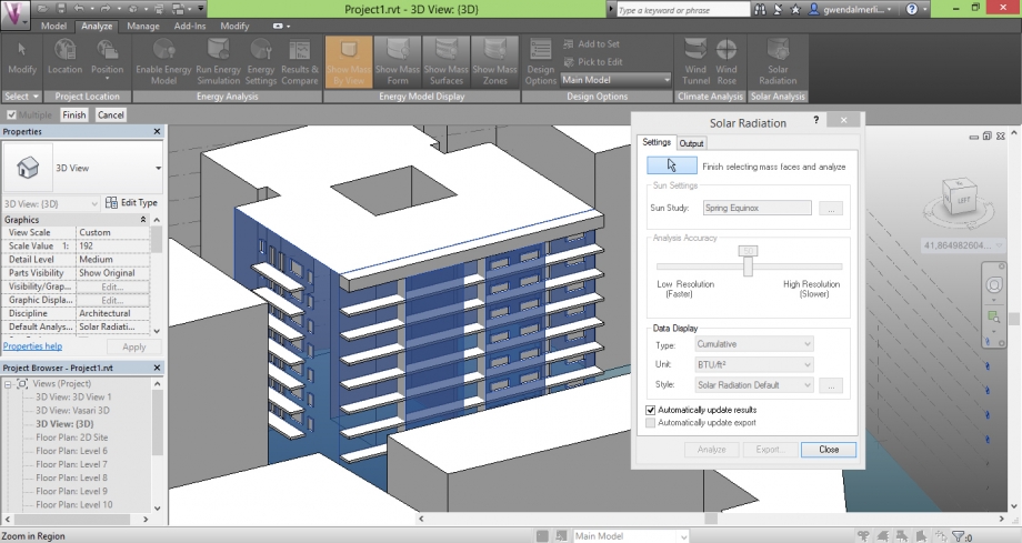
Nella lista "sun settings" è possibile scegliere la data alla quale l'analisa è fatta. Ci sono dei parametri già registrati che possiamo utilizzare. Come "winter" o "summer".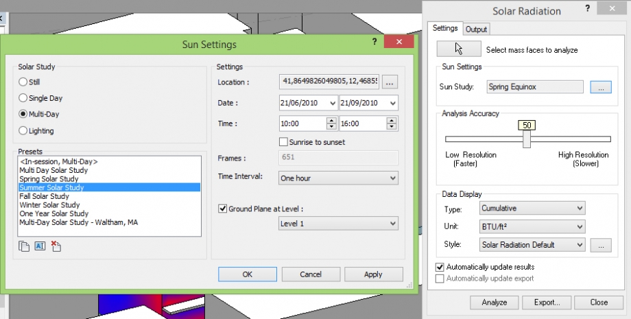
Poi, dobbiamo cambiare gli stili analisi che utilizziamo per le analisi più precise.
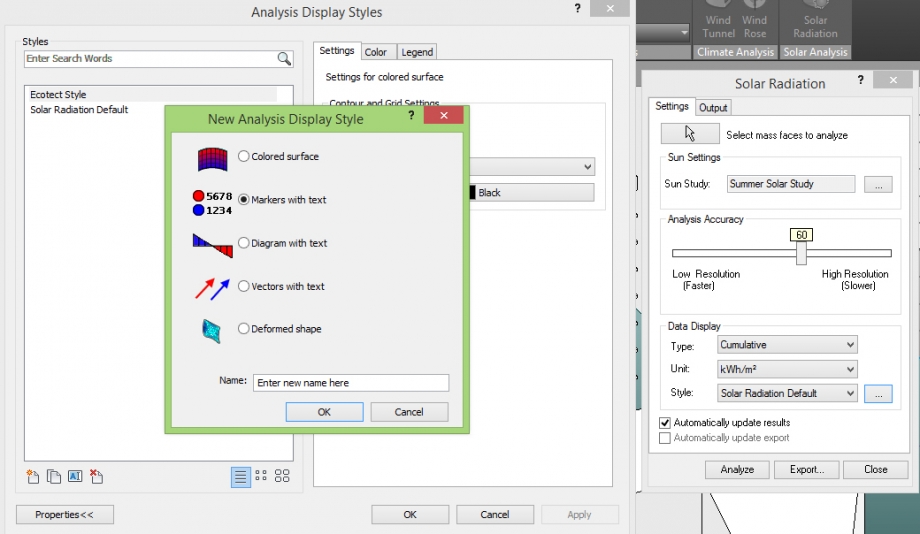
Per ciò bisogna andare nella lista "data display" e creare un nuovo stile. Ne abbiamo creato due nuovi. (Non dimenticare di passare in kWh/m²)
Il primo è un'analizia « colored surface », dobbiamo solo cambiare le colore, perché è migliore di avere il rosso per il caldo, e il blu per il freddo.
La seconda è un'analizia « markers with text ». Ancore una volta, è migliore di cambiare le colore. Qua, è possibile di cambiare anche il text (Non siamo riusciti a cambiare la dimensiona del testo).
Terza parte : Solar radiation analizia
A - Valutazione degli spazi esterni col metodo « colored surface »
L'edificio è composto di numerosi balconi e loggia su tutto il giro. È molto interessante vedere le radiazioni solari su questi spazi dunque molto utilizzati.
Per potere studiare ciò, abbiamo deciso di utilizzare le date predefinite. Dunque l'inverno e l'estate perché sono due periodi estremamente oppositore.
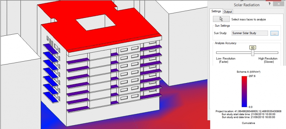 Facciate Nord-Ovest e Sud-Ovest in estate.
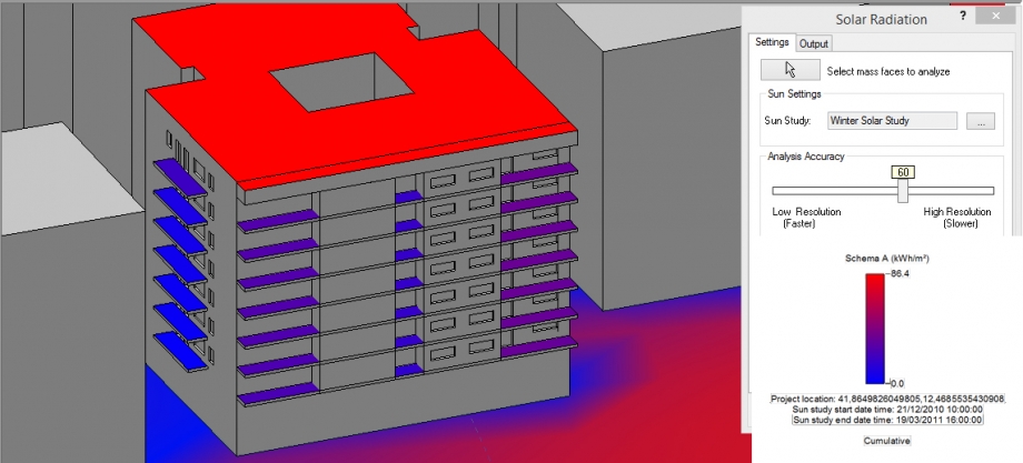
Facciate Nord-Ovest e Sud-Ovest in inverno.
Paragonando i due schemi ottenuti, non vediamo un'importante variazione subito. Ma se guardiamo le valore, vediamo però che in realtà, in estate gli spazi sono buoni più esposti ai radiazioni solari. Passiamo di 297 in estate al massimo, a 86 in inverno.
Certamente, il tetto è più esposto poiché non ci ha niente da impedire i radiazioni solari di raggiungerlo. Invece, i balconi fanno una maschera a quelli sotto. Dunque le radiazioni sono meno importante. Ma ciò è meglio, perché i balconi orientati al Sud hanno bisogno di una protezione al sole se no, la temperatura sarebbe troppo importante ed non sarebbe piacevole di essere qui. Infine, la facciata Nord che ha meno di finestre e balconi sono buone più all'ombra che la facciata Sud, poiché il sole non la tocca direttamente. Più c'è un altro edificio molto vicino.
B – Valutazione delle facciate col metodo « colored surface »
Questa volta ci siamo interessati alle facciate opache per vedere a che punto erano sottomesse alle radiazioni solari.
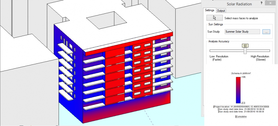
Facciate Nord-Ovest e Sud-Ovest in estate.
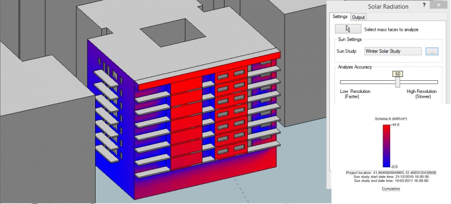
Facciate Nord-Ovest e Sud-Ovest in inverno.
La facciata Sud è qui più interessante, perché non c'è praticamente cambiamento sulla facciata Nord-ovest.
Ancora questa volta, bisogna fare attenzione ai valori. Perché potremmo credere che ci sono più di radiazioni solari in inverno che in estate.
Le parti che sono senza balconi prendono un massimo di sole, con un valore di 106 in estate, ciò che è proprio molto. I balconi sono raggiunti al contrario meno, ma ciò è una buona cosa, perché il sole non può battere sulle finestre in estate. Al contrario, in inverno il sole è più basso, e noi possiamo vedere che raggiunge praticamente tutte le facciate.
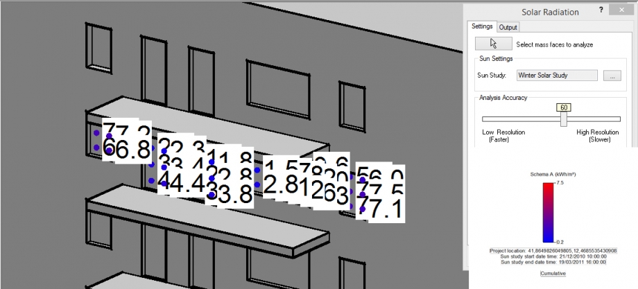
C - Valutazione delle finestre e porte col metodo "Markers with text"
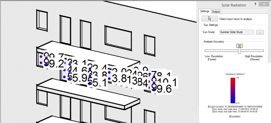 Facciata Nord-Ovest in estate.
Facciata Nord-Ovest in inverno.
Facciata Sud-Ovest in estate.
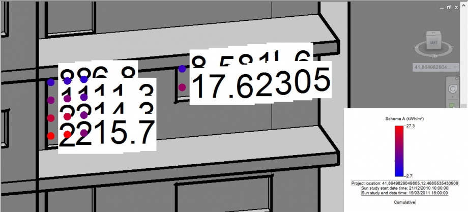 Facciata Sud-Ovest in inverno.
Come mentre l'inverno l'altezza del sole e più bassa possiamo vedere che su i balconi sud-ovest la valore di lucce ricivuta è più importante sulla parte alta perche il balcone superiore non fa ombre invece del'estate quando il sole è più alto.
Per la facciata nord-ovest globalmente come quella è meno esposta le valore sono proporzionalmente eguale c'è solo la caduta di gradi legata alla stagione.
Possiamo concludere dunque che i balconi sostengono un ruolo di per-sole. Stato fanno dell'ombra agli alloggi e permettono di non avere una temperatura troppo elevata l'estate. L'inverno quando il sole è meno importante, lo lasciano però penetrare negli alloggi per portare un poco più di luce e di caldo.
I balconi sono allora bene più di semplici spazi esterni dove sedersi o stendere la sua biancheria.
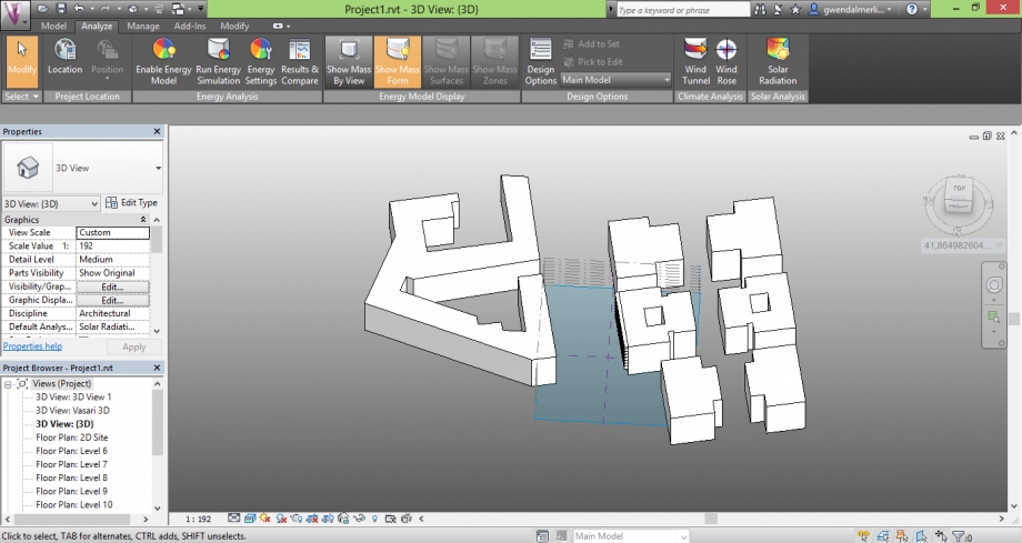
Quarto parte : Studio del sito di progetto
Abbiamo disegnato nostro progetto per cui gli alloggi abbiano una buona repartizione della luce mentre la gioranta.
Quelli sono tutti attraversanti.
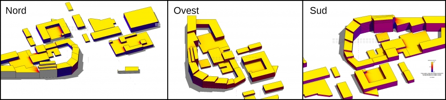
Osservazione delsoleggiamento mentre i solstizi e i equinozi sulle due faciate de l'edificio.
Equinozio di primavera
 9:00 12:00 18:00
Solstizio d'estate
9:00 12:00 18:00
Equinozio di autunno
9:00 12:00 18:00
Solstizio d'inverno
9:00 12:00 18:00
Su la base de analise solare vediamo che le faciate che prendono il più di sole sono per la majorità quelle che fanno fronte a la corte interna.
Quello per motivo di avere la concentrazione delle attività verso l'interno del quartière perchè la circulazione è molto più forte sull'altra faciata (via del porto fluciale).
Dati della media perioda estiva Dati della media perioda invernale
Nicolas Gualtieri
Gwendal Merlin
Lun, 27/04/2015 - 21:16