 Cattaneo_Corti
Dom, 22/03/2015 - 19:22
Cattaneo_Corti
Dom, 22/03/2015 - 19:22
TUTORIAL
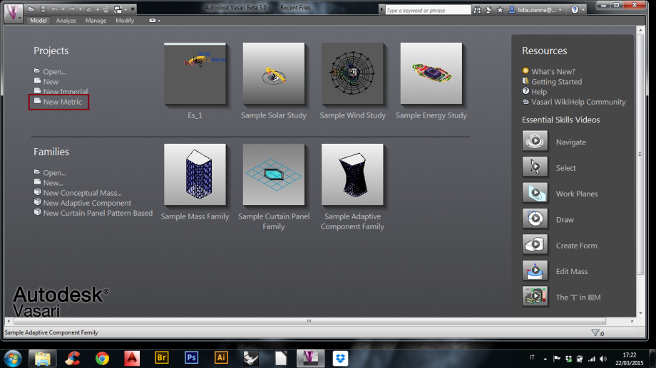
1. Dopo aver aperto il programma, per creare un nuovo file cliccare su “New Metric”;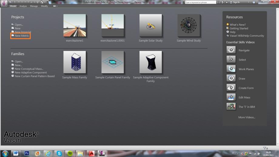
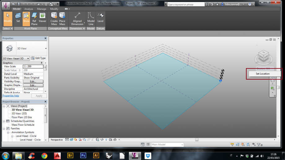
2. Per selezionare l’area di interesse cliccare su “Set Location”;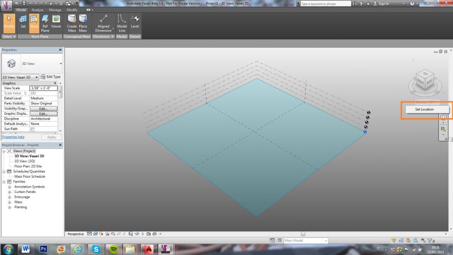
3. Dopo aver aperto la finestra, digitare l’indirizzo desiderato e poi cliccare “Import Site Image…”;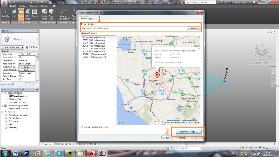
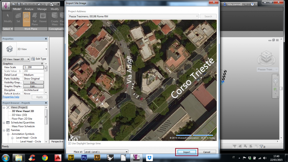
4. Aperta la finestra con l’immagine planimetrica cliccare “Import”;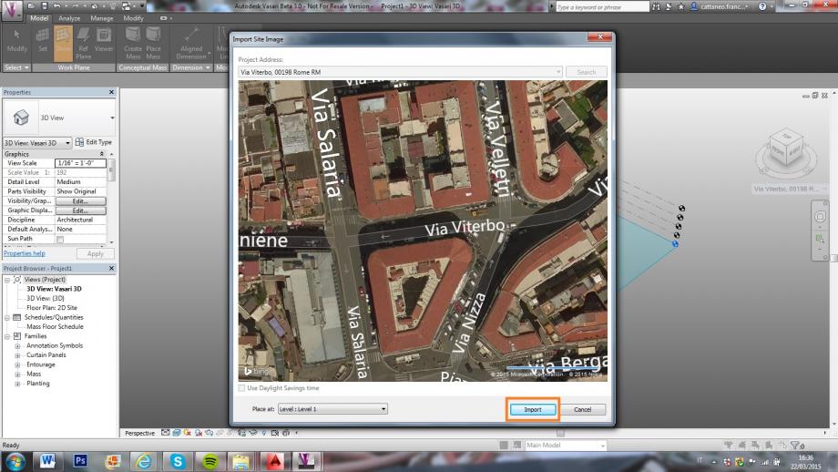
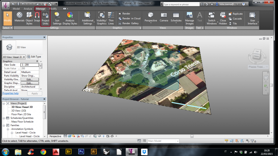
5. Dopo aver cliccato su “Manage”, per cambiare le unità di misura cliccare su “Project Units”;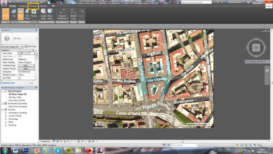
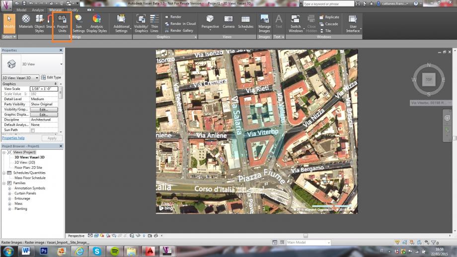
6. Dopo aver aperto la finestra, cliccare su “Length”;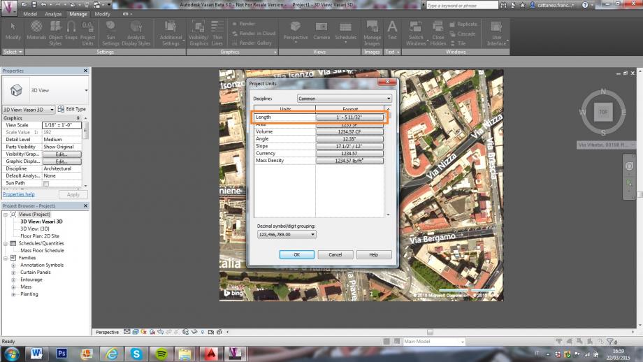
7. Inserire i metri e cliccare “Ok”;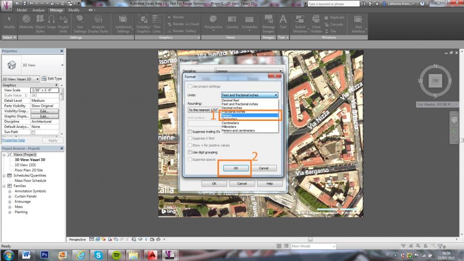
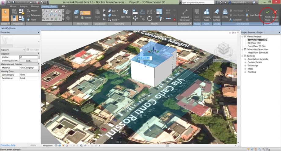
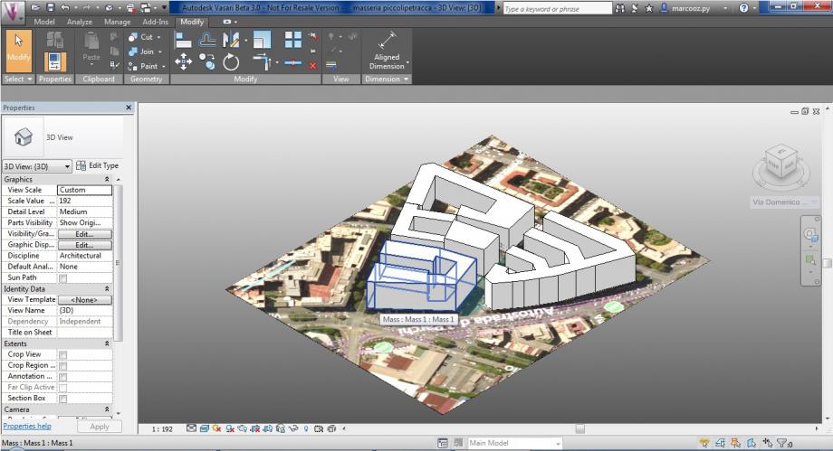
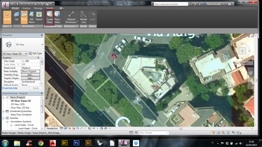
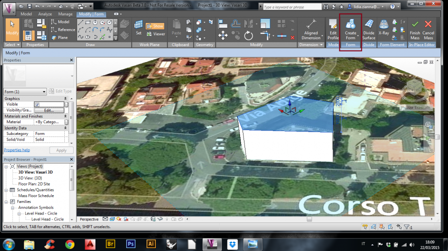
8. Per creare una forma, cliccare su “Create Mass”;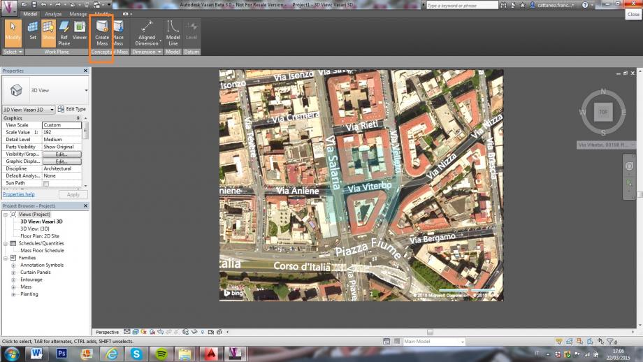
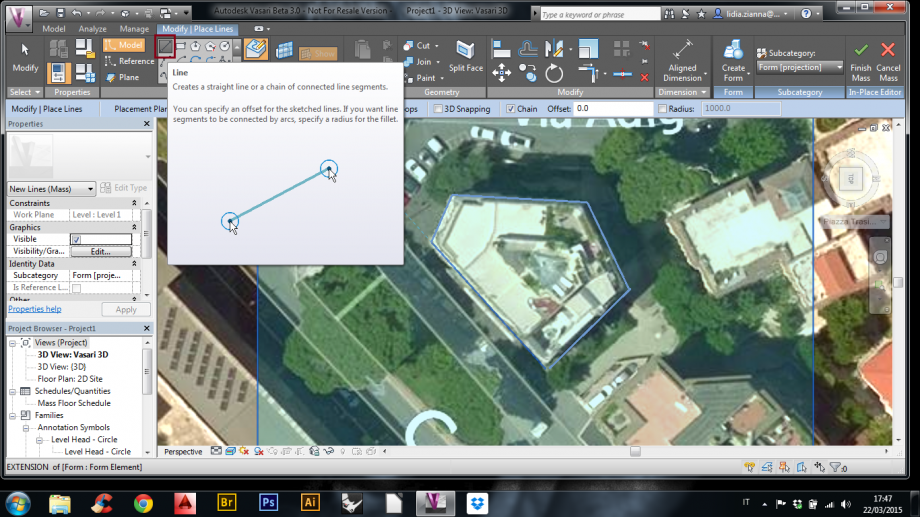
9. È possibile disegnare attraverso linee, rettangoli, poligoni… ;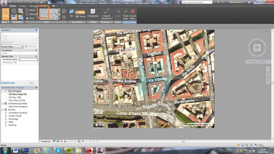
10. Dopo aver disegnato il perimetro dell’edificio cliccare su “ Create Form”;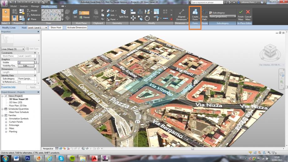
11. È possibile regolare l’altezza cliccando sulla freccetta blu rivolta verso l’alto;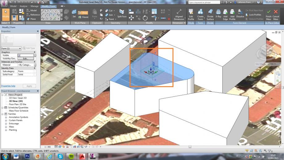
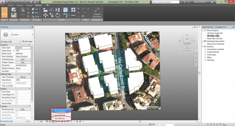
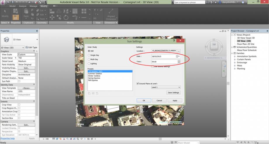
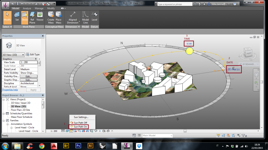
12. Cliccare su “Sun Settings” per selezionare data e ora;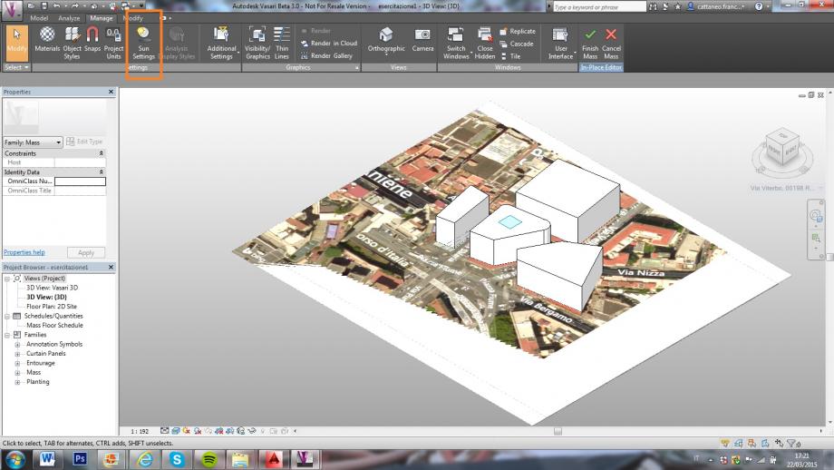
13. Selezionare data e ora;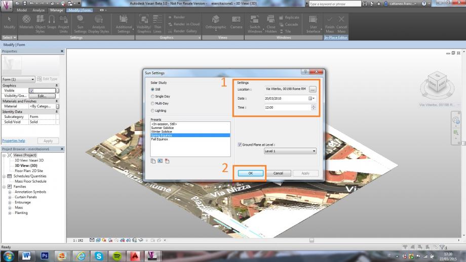
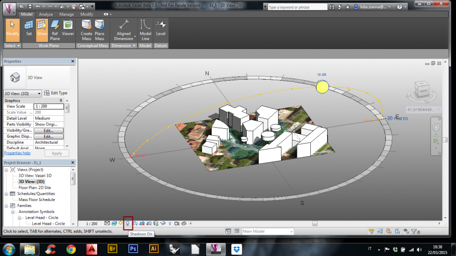
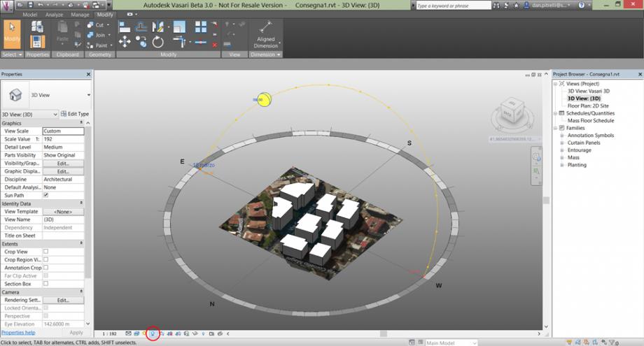
14. Per inserire le ombre cliccare su “Shadows On” e per inserire il sole cliccare su “Sun Path On”;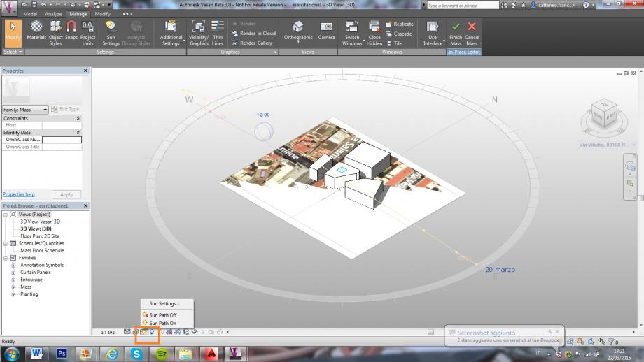
15. È possibile regolare l’ora anche cliccando sul sole;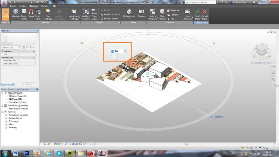
16. È possibile cambiare la data cliccando sulla data stessa;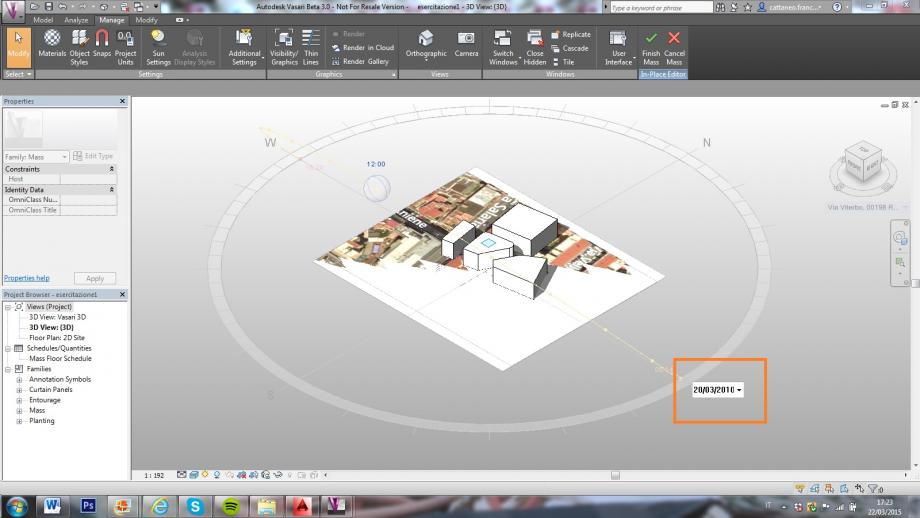
17. Per cambiare la vista cliccare su “Camera” e posizionarla a proprio piacimento.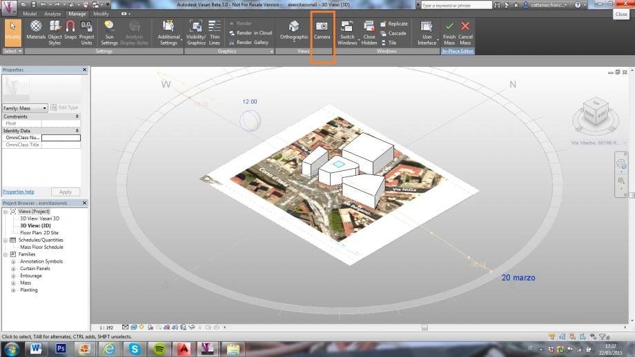
ANALISI
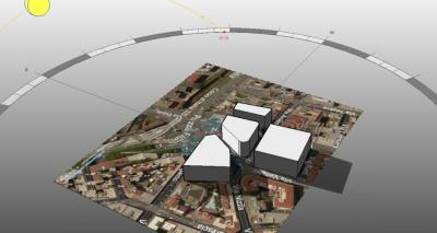
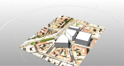
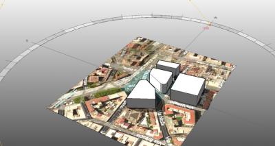
L’area da noi presa in considerazione si trova a Roma nel quartiere Pinciano. L’edificio da noi analizzato presenta quattro prospetti (esposti circa a nord, sud, ovest e sud-est), affaccia su Piazza Fiume ed è circondato su tre lati da fabbricati che hanno più o meno la stessa altezza (sei piani ciascuno): questo fa si che questi non proiettino gli uni sugli altri grandi ombre creando talvolta, soprattutto nel periodo estivo, delle condizioni sfavorevoli al comfort abitativo.
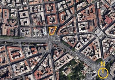 Planimetria
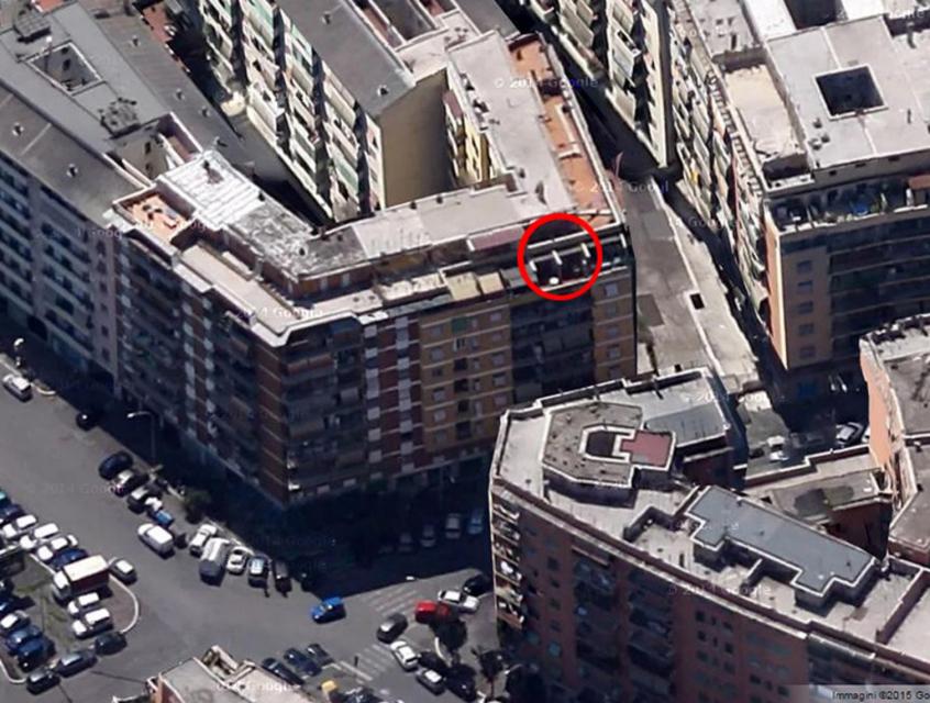
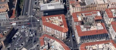 Zoom area
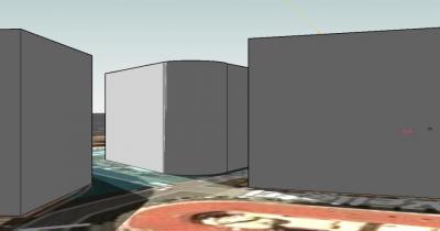
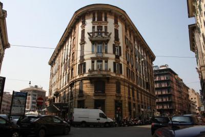
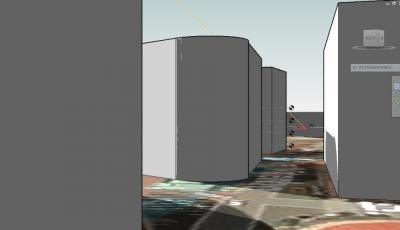
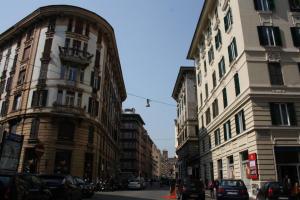
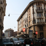
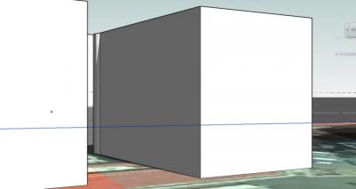
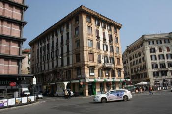
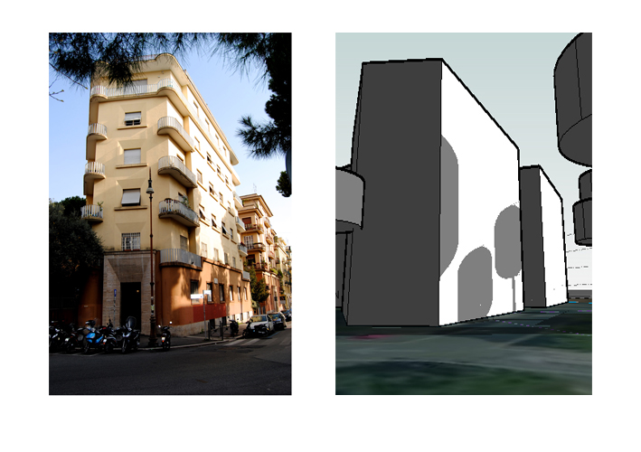
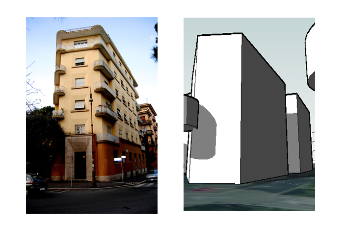
Abbiamo scattato queste foto da Via Nizza verso due punti diversi alle 13.17 del 20 marzo, inquadrando l’edificio da noi preso in considerazione. L’area da noi esaminata ha una leggera pendenza, che, come si può notare nella prima coppia di immagini a confronto, non ci ha permesso di verificare del tutto il reale ombreggiamento di un edificio sull’altro. Questa facciata è esposta a sud-est e, nonostante la presenza dell’edificio antistante che, come possiamo notare dalla foto, crea ombra sul prospetto, è nelle ore più calde della giornata quasi completamente colpita dal sole. Nella seconda coppia di immagini, nonostante il dislivello, siamo riuscite a verificare parzialmente l’ombreggiamento di un edificio sull’altro. Infatti, l’edificio a sinistra, la cui facciata su Via Viterbo è esposta a nord, proietta la propria ombra solamente sui piani più bassi dell’edificio prospiciente.
Spostandoci invece su Piazza Fiume, abbiamo verificato che la facciata su Via Salaria, esposta a ovest, alla suddetta ora è ombreggiata. Il prospetto a sud, invece, è completamente soleggiata in qualsiasi giorno dell’anno in quanto affaccia sulla piazza. Questa situazione provoca scarso comfort abitativo durante il periodo estivo.
Abbiamo inoltre studiato l’ombreggiamento alle ore 12, orario critico per il soleggiamento, nei solstizio d’estate e in quello d’inverno e nell’equinozio d’autunno.
 21 dicembre
 21 giugno
 23 settembre
Abbiamo notato come la facciata esposta a sud-est, che è una delle due facciate più problematiche, sia in queste date sempre irraggiata. Questa analisi potrebbe tuttavia non essere del tutto corretta per il piano terra data la leggera pendenza del sito.
Nello studio dell'edificio da noi preso in considerazione, abbiamo inserito un aggetto di 1,50 m che ci è sembrato interessante, utilizzato per schermare il piano terra nei prospetti sud, sud-est e ovest dove è presente una banca. Abbiamo riproposto lo studio alle ore 13.17 del 20 marzo: come possiamo notare, l’aggetto, nella facciata a sud-est scherma del tutto i raggi solari, a differenza di quello che avviene nel prospetto che affaccia sulla piazza, in cui i raggi vengono schermati solo parzialmente.
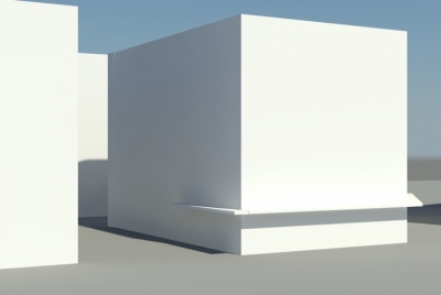
Abbiamo confrontato questa situazione con i solstizi nella stessa fascia oraria. Nel prospetto sud-est l’aggetto ha la stessa efficacia nello schermare i raggi solari. Nel prospetto sud l’aggetto ripara dai raggi solari in estate, mentre li lascia penetrare nel periodo invernale: questo può rivelarsi positivo in entrambi i casi.
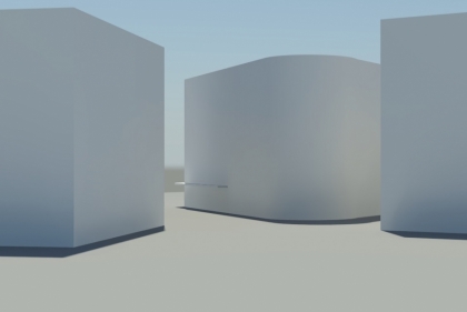
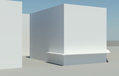
21 giugno h. 13.17
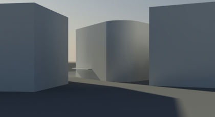
21 dicembre h. 13.17
Dom, 22/03/2015 - 19:36
 Mat.Cavuoti
Dom, 22/03/2015 - 18:23
Mat.Cavuoti
Dom, 22/03/2015 - 18:23
SHADING ANALYSIS TUTORIAL
In this tutorial we'll show you how to set a project in Autodesk Vasari for a shading analysis.
STEP 1: Creating a new file and loading location and weather data
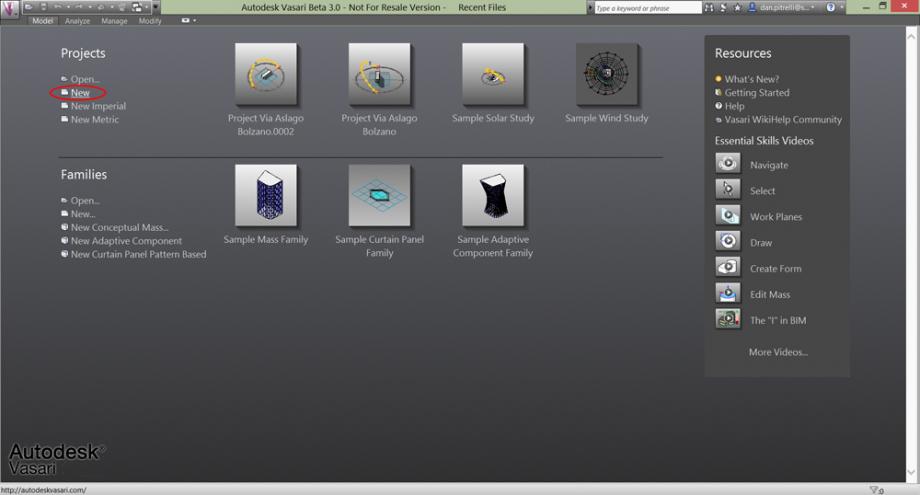
Start a new project on Vasari clicking on 'New'.
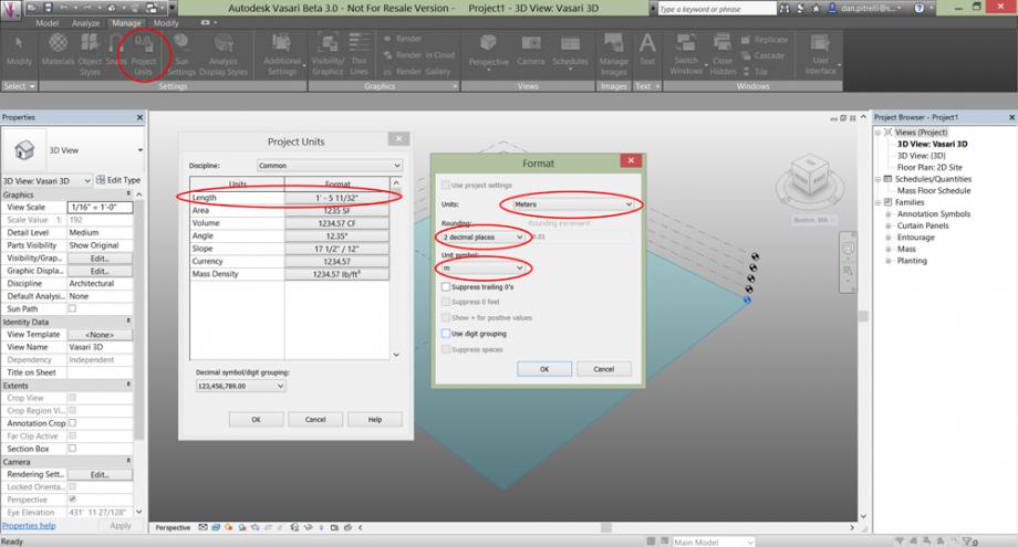
Select 'Manage' on the top and then 'Project Units'. In the new window set the 'Format' of the unit 'Lenght' by clicking on it. Now select 'Meters' as project units.
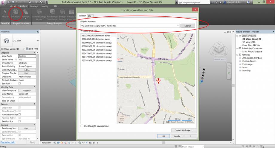
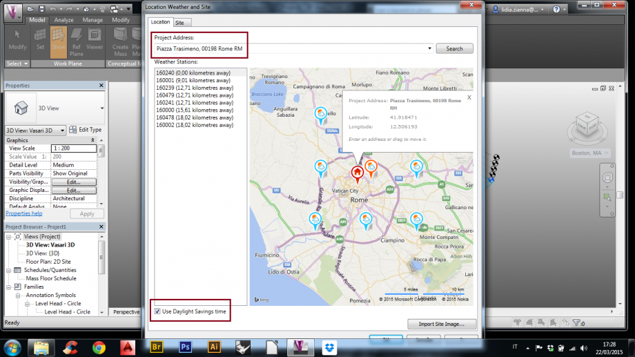
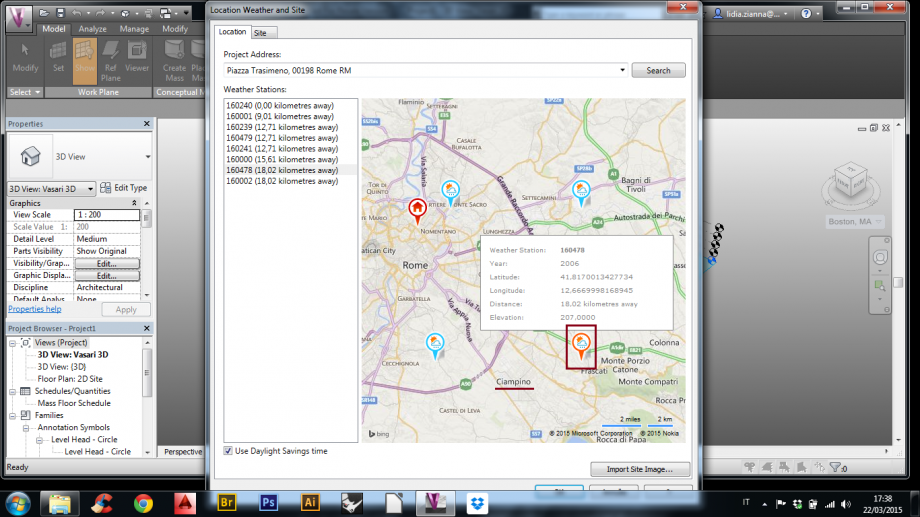
On the top select 'Analize', and then 'Location'. In the Project Address form type the address of the site you want analize, click on 'Search' and select the corresponding icon.
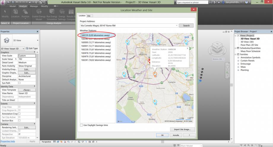
Now select the nearest Weather Station by double clicking on it.
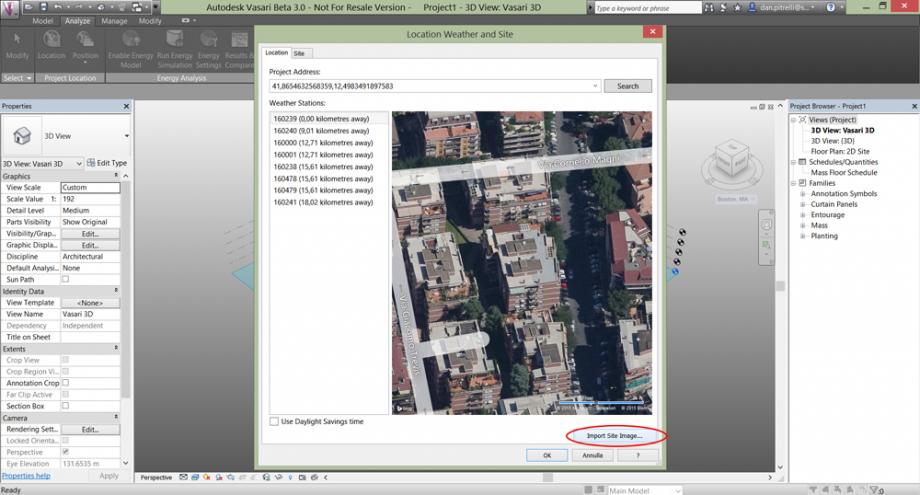
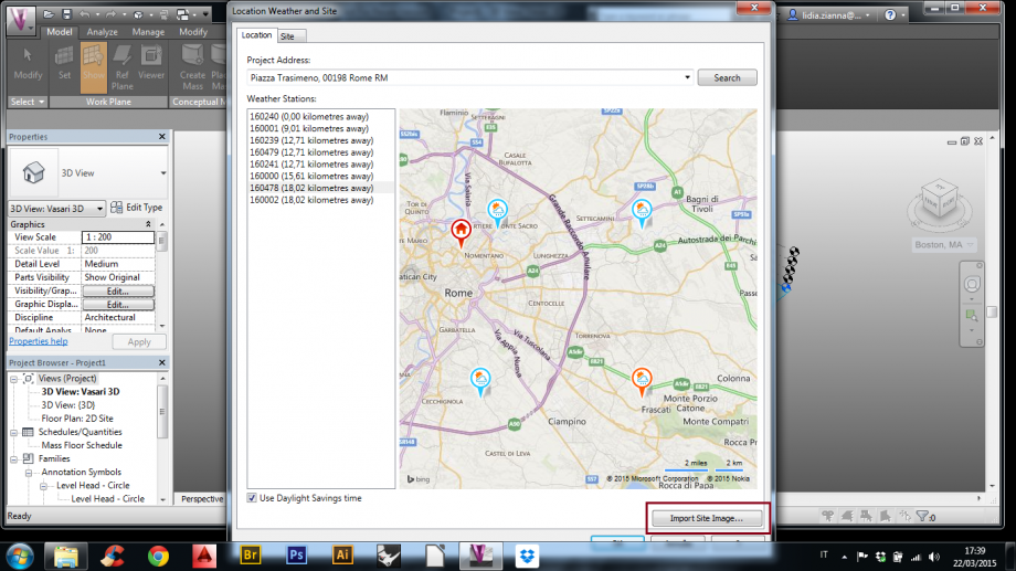
Then click on 'Import Site Image...'.
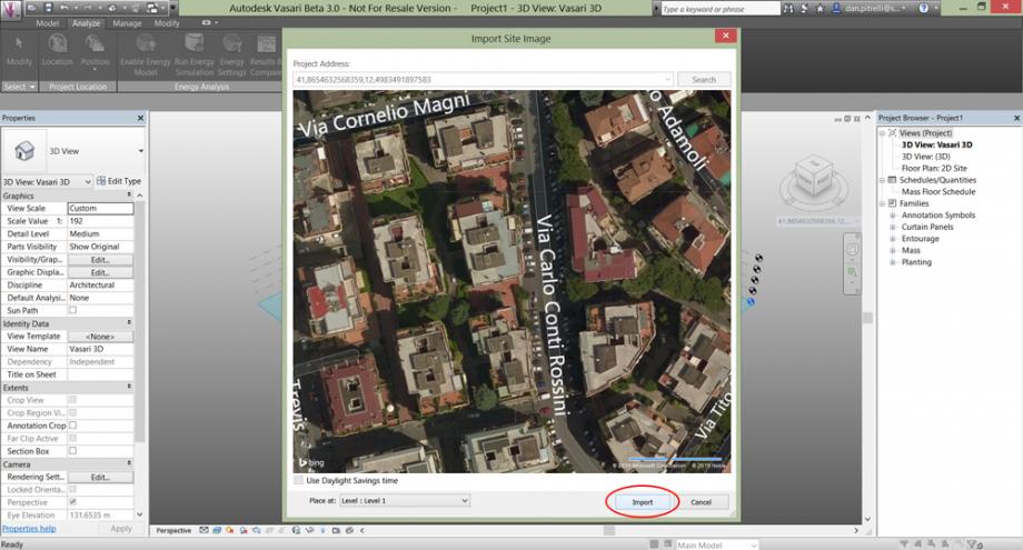
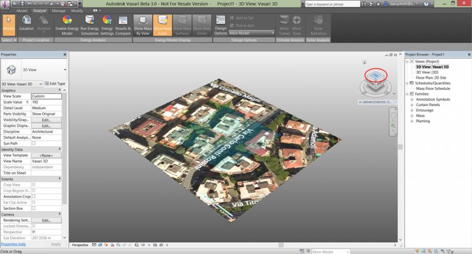
You will obtain an orthographic satellite view of the selected site. Zoom and pan the image to fit the area.
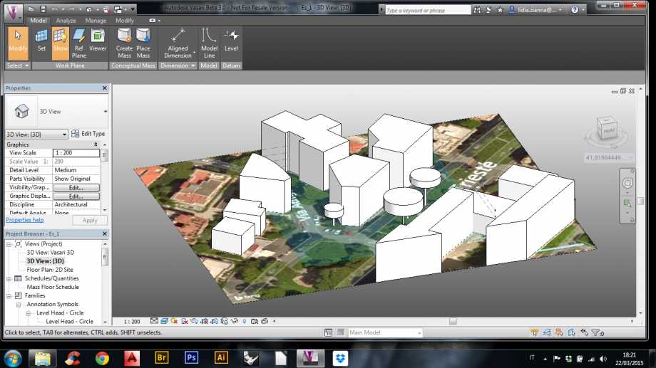
STEP 2: Modeling the buildings
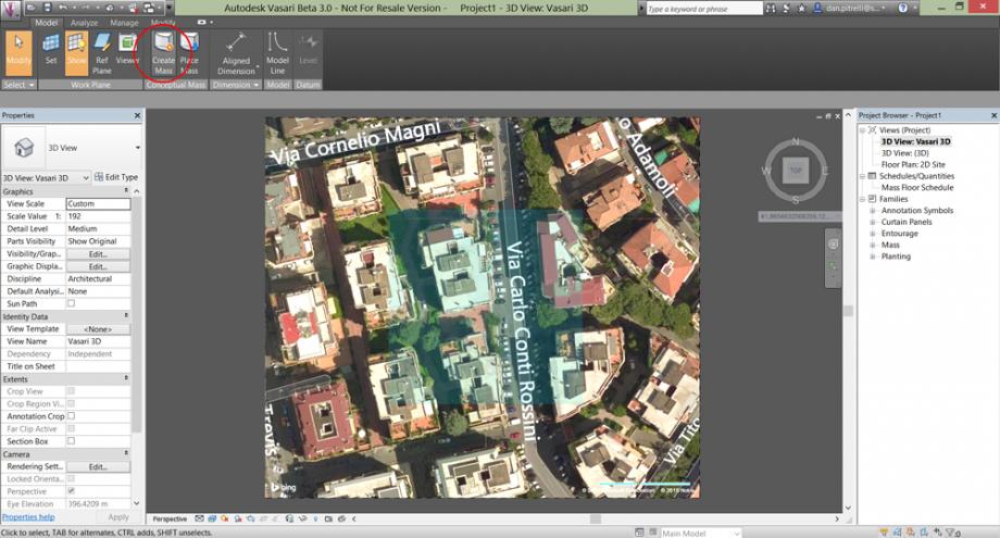
Set the view on “top” and click on “Create Mass” in the Model toolbar.
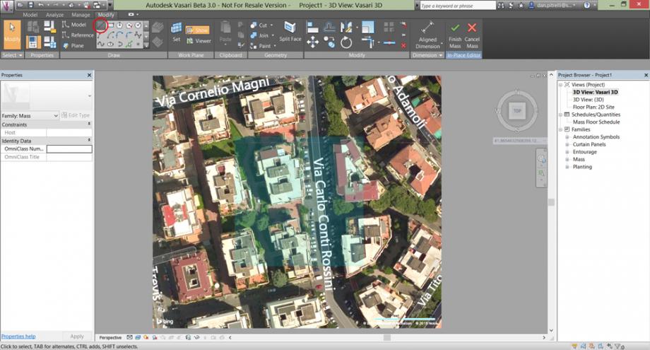
Use the “Line” command to draw the building you want.
Set the view again on “3D View”
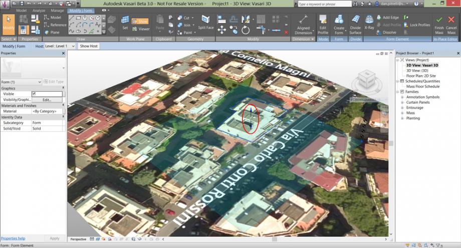
Then extrude the line you made by clicking inside the shape and dragging the blue arrow pointing up/top.
Insert the building height.
STEP 3: Setting the Sun
On the bottom of the screen you shall see an icon of the sun, click on it and then on “Sun Path On”. You can also set the day and the time.
Near to the sun icon there is the Shadows icon, turn also the shadows on.
There it is! Now you see the sadows of those buildings in that precise place on the earth, at that precise day and hour.
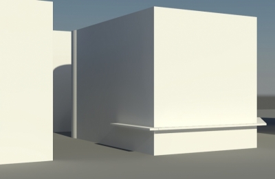
SHADING ANALYSIS OF A BUILDING LOCATED IN VIA CORNELIO MAGNI, ROME – ITALY
The building we are analizing is located in Roma, in ‘quartiere Ardeatino’ – via Cornelio Magni, into a residential complex.
It is important to value the shading of the near buildings on our one during the year.
We chose to show the shading during the solstices and equinoxes days.
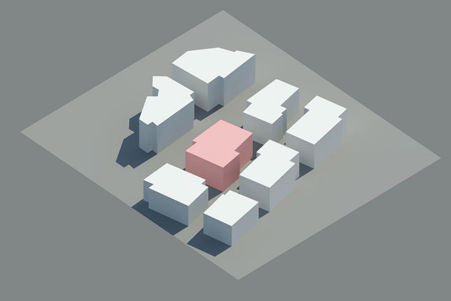 Autumnal Equinox 22-09-2015 h. 12:00.
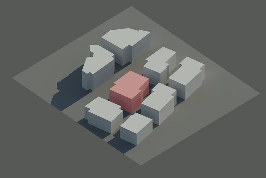
Winter Solstice 21-12-2015 h. 12:00.
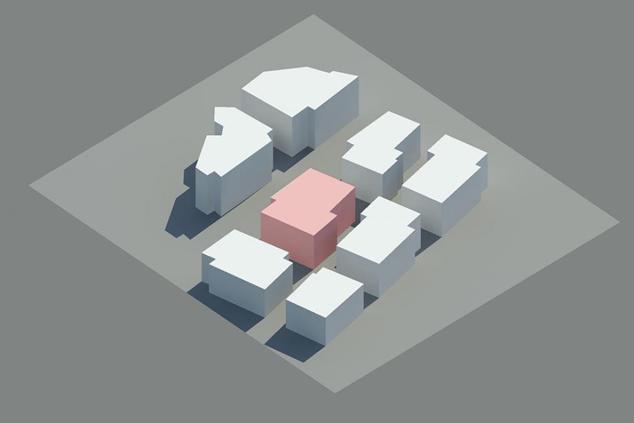
Spring Equinox 20-03-2015 h. 12:00.
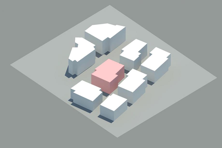
Summer Solstice 21-06-2015 h. 12:00.
Daily Trend Analysis
We decided to study the west facade, on which there are a few balconies, but we did not consider them in this exercise.
Day 18-03-2015 at hour …
09:00
11:00
12:00
14:00
15:30
We noticed that the facade is sunlit only a few hours in the afternoon.
Matteo Cavuoti & Danilo Pitrelli
Dom, 22/03/2015 - 19:00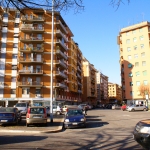 petracca_piccoli
Dom, 22/03/2015 - 16:07
petracca_piccoli
Dom, 22/03/2015 - 16:07
ESERCITAZIONE 1 – ANALISI DELL'OMBREGGIAMENTO
PREMESSA- INTRODUZIONE A VASARI
Per questa analisi e le successive utilizzeremmo il software sperimentale Autodesk Vasari che permette ai progettisti un controllo accurato dei volumi edilizi e delle loro articolazioni, sulla base di tre tipi di analisi:
- analisi della radiazione solare;
- analisi dei venti;
- analisi delle prestazioni energetiche.
Lo sviluppo di un modello adeguatamente accurato su Vasari permette non solo la verifica delle condizioni ambientali in qualsiasi periodo dell'anno, ma anche la gestione di questi dati per altri fini progettuali come la riduzione dei ponti termici, come vedremo in seguito.
DESCRIZIONE DELLO SCOPO E DELLA PROCEDURA DELL'ESERCITAZIONE
In questa esercitazione ci chiediamo come variano le ombre sull'edificio di studio, e come cambiano in diversi periodi della giornata e dell’anno.
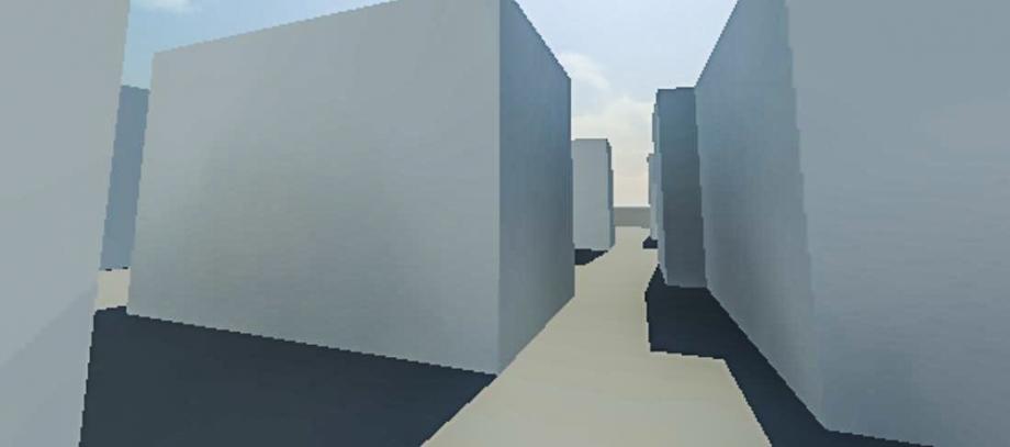
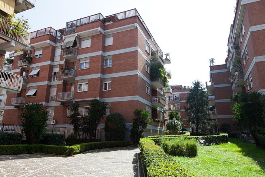
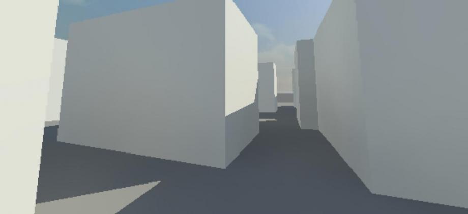
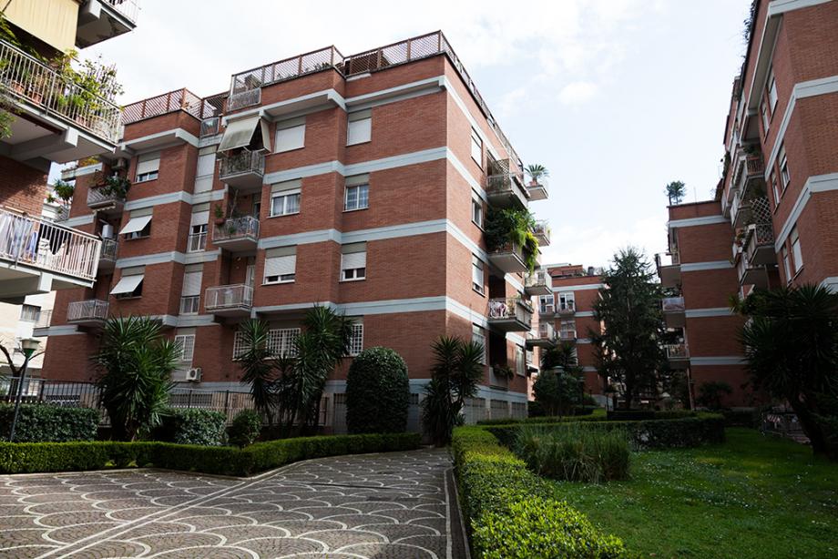
Costruiremo allora un modello veritiero, in prima approssimazione, dei volumi edilizi presenti nella nostra zona di riferimento e compareremo le immagini prodotte dal programma con delle fotografie scattate a determinate ore della giornata, per verificare l'accuratezza delle informazioni che Vasari ci restituisce.
Fatto ciò potremo considerare il modello per delle analisi dell'ombreggiamento in periodi di interesse, quali il solstizio d'inverno e l'equinozio estivo.
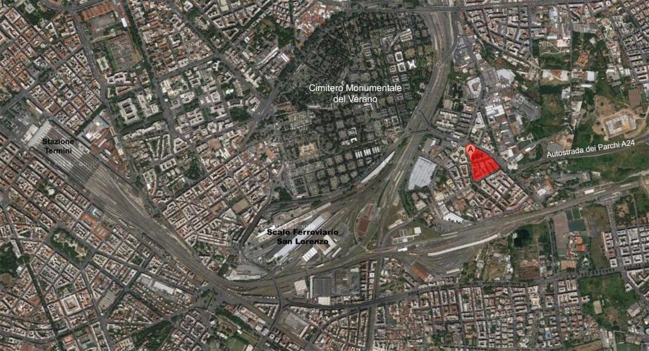
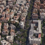
DESCRIZIONE DELL'AREA DI ANALISI
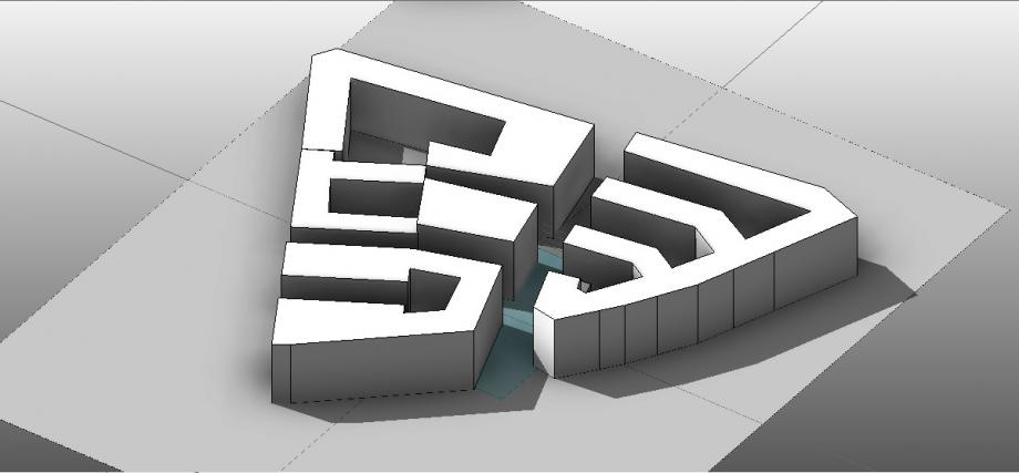
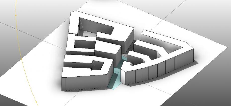
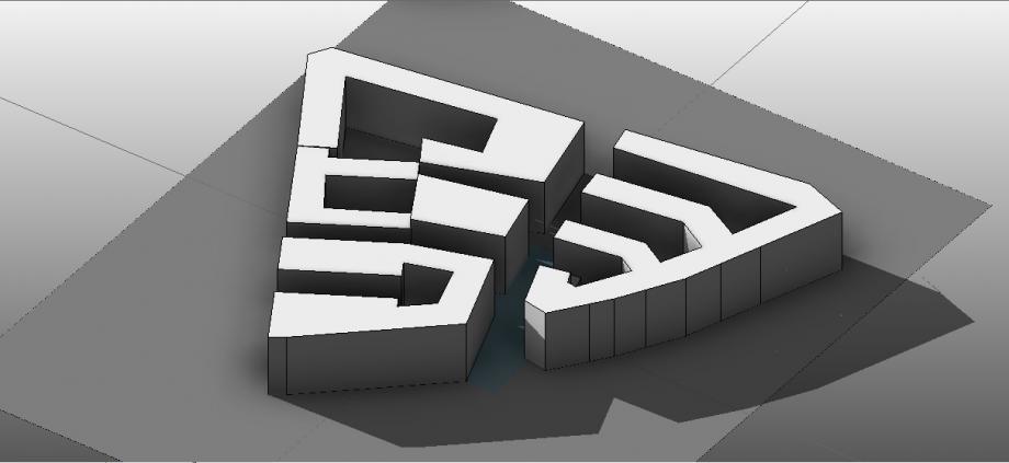
L'area di studio si trova nella parte orientale del quartiere tiburtino, a poca distanza dall'ingresso dell'autostrada dei parchi. Il tessuto edilizio di questa parte di città è fortemente compatto e prevalentemente residenziale. Nei volumi edilizi prevale ampiamente la tipologia a corte, declinata con i caratteri distintivi dell'edilizia residenziale della seconda metà del Novecento.
Le altezze degli edifici si aggirano mediamente tra i 7 e gli 8 piani, circa 24-27 metri.
Sono tutti edifici molto massivi, privi di grandi aperture vetrate, con poche logge, sovente sostituite da balconi sulle facciate che affacciano verso la strada.

L'appartamento dove condurremmo anche la prossima esercitazione si trova all'ottavo piano dell'edificio ed espone completamente a nord.
Elencheremo di seguito, passo dopo passo, le fasi condotte per costruire un modello preliminare dei volumi edilizi, che successivamente sarà utilizzato per fare previsioni sull'ombreggiamento in diversi periodi dell'anno.
PROCEDURA OPERATIVA SU VASARI
FASE 1. Unit meters
Avvio del software Autodesk Vasari. Aprire un nuovo documento e inserire le unità metriche di progetto cliccando sul comando “Project Units” indivituato nella sezione “Manage” nella barra di comando. (fig.1)
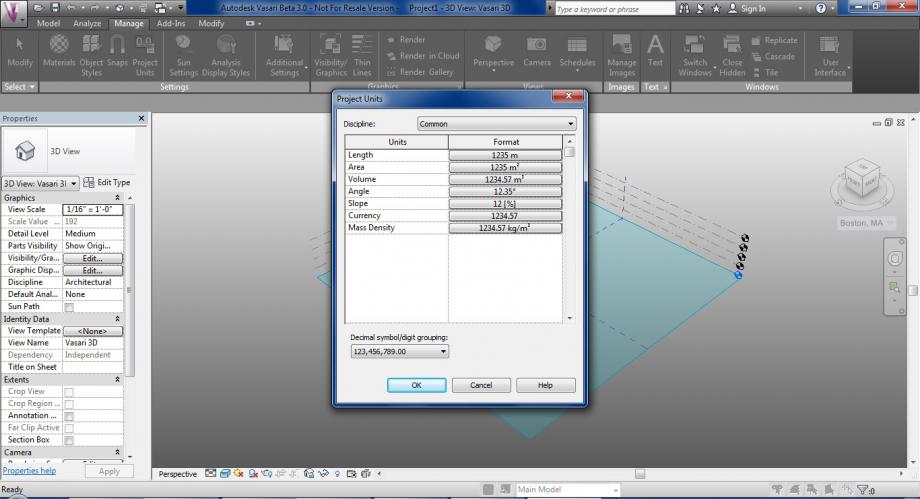
(fig.1)
manage_settings_project units
FASE 2. Orthographic view
Impostare la vista ortografica per preparare l'area di lavoro ad una comoda modellazione dello spazio. Quindi, sempre nella barra “Manage” individuare il comando “Perspective view/Orthographic view” e cliccare nel suo sottocomando “Orthographic”. Imposto la vista su “top” cliccando sul cubo di visualizzazione a destra dello schermo. (fig.2)
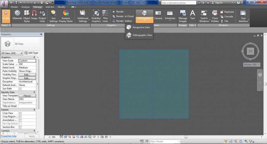
(fig.2)
manage_views_orthographic
FASE 3. Project location
Impostare l'area di analisi georeferenziata. Il nuovo documento si autolocalizza su Boston. Andare a settare l'area cliccando su “Analyze” sulla barra di comando, e quindi cliccare il comando “Set Location”. Nella finestra apertasi inserire l'indirizzo dell'edificio preso in esame e cliccare sulla stazione metereologica più vicina tra quelle indicate nell'elenco a destra. Ultimati tali operazioni, cliccare su “Import site image” (fig.3) ;
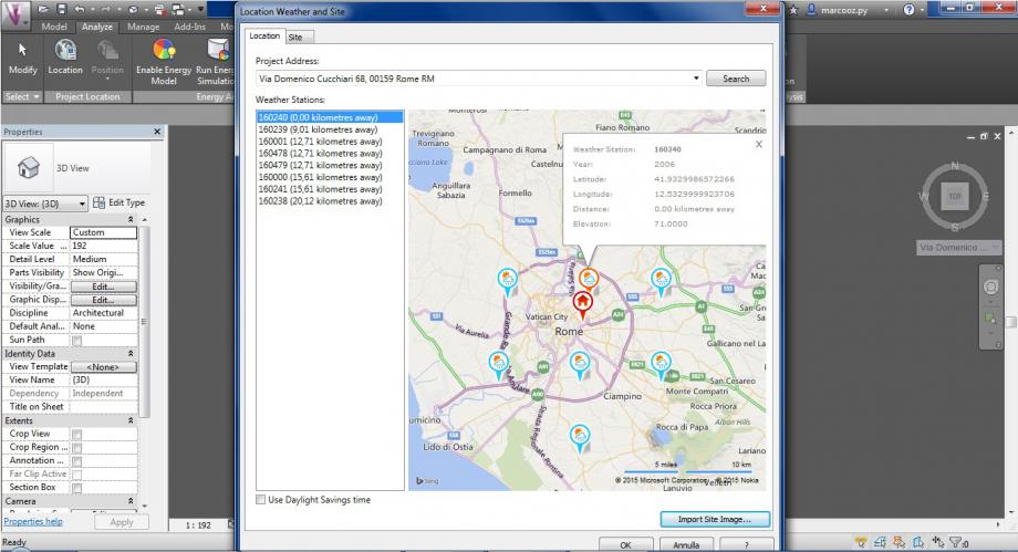
(fig.3)
si aprirà un ulteriore finestra con l'immagine satellitare dell'area che permetterà quindi scegliere la scala più opportuna della zona. (fig.3.1)
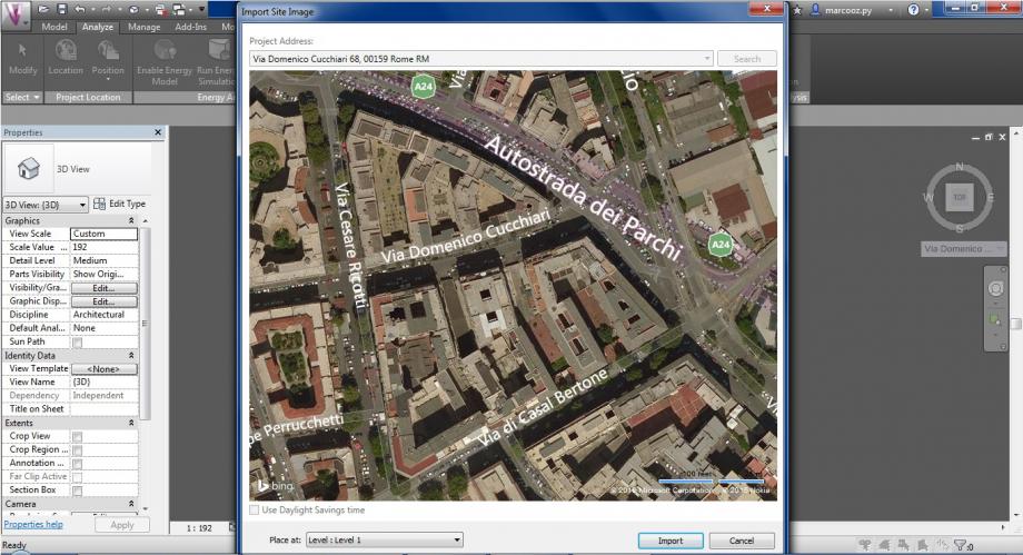
(fig.3.1)
analyze_projectlocation_location
FASE 4. Model. Create Mass
Per creare i volumi andare su “Model” situato sulla barra di comando e cliccare “Create Mass” (fig.4).
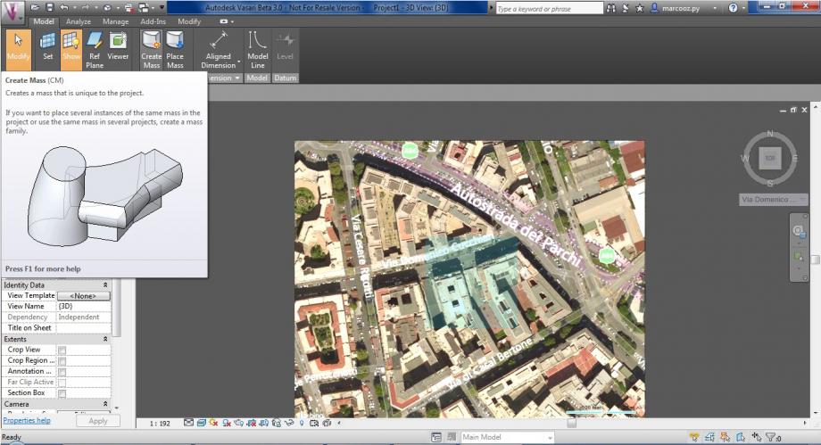
(fig.4)
Iniziare tracciando i contorni di base degli edifici con il comando “line” e, una volta chiusi, premere “esc” (fig.4.1).
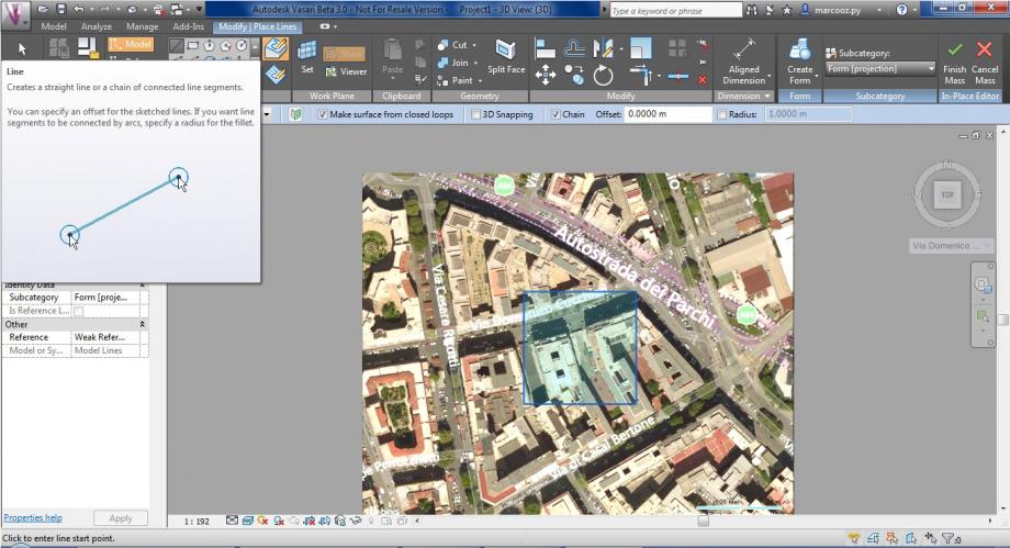
(fig.4.1)
L'area racchiusa dalla linea risulterà biancastra: questo permetterà, una volta cliccatoci dentro di estrudere il volume e di impostarne l'effettiva o un approssimata (circa 3 metri per piano) altezza in metri (fig.4.2.1 fig.4.2.2).
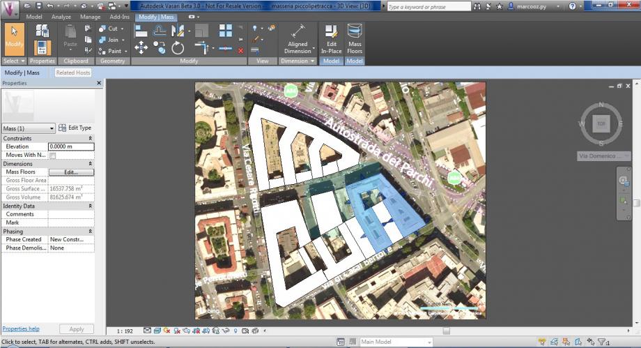
(fig.4.2.1)
(fig.4.2.2)
model_createmass_line
FASE 5. Sun Settings
Una volta ultimata la modellazione, so può procedere con le analisi che il software ci può offrire.
Bisogna impostare quindi una data e un ora che ci permetterà di ottenere gli ombreggiamenti/soleggiamenti nel modello 3d.
Nella riga di comando in basso, attivare i comandi “Sun Path on” e “Shadows On”. Ora cliccare nella barra di comando “Manage” e cliccare sul pulsante “Sun Settings” (fig.5). Nella finestra apertasi, andare ad impostare data e ora di analisi.
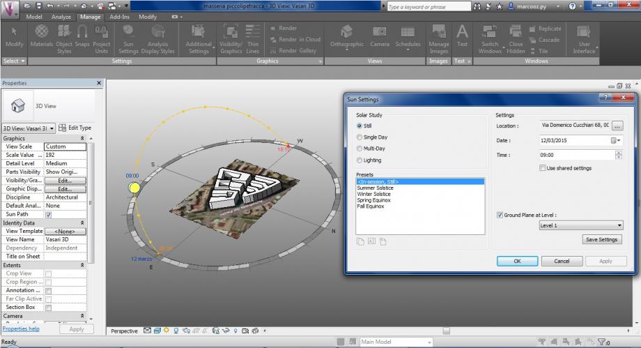
(fig.5)
manage_sunsettings
ANALISI DELL'OMBREGGIAMENTO
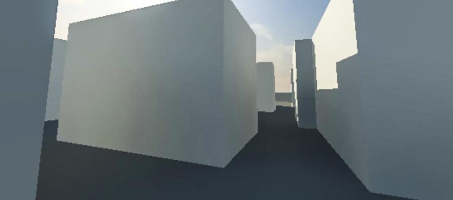
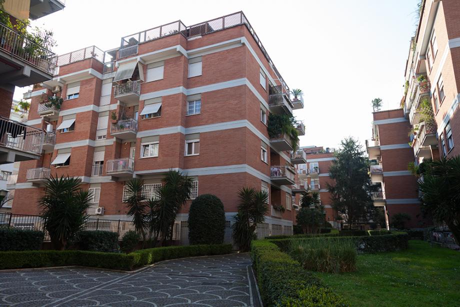
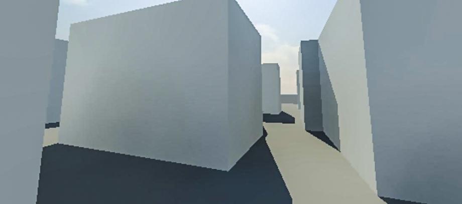
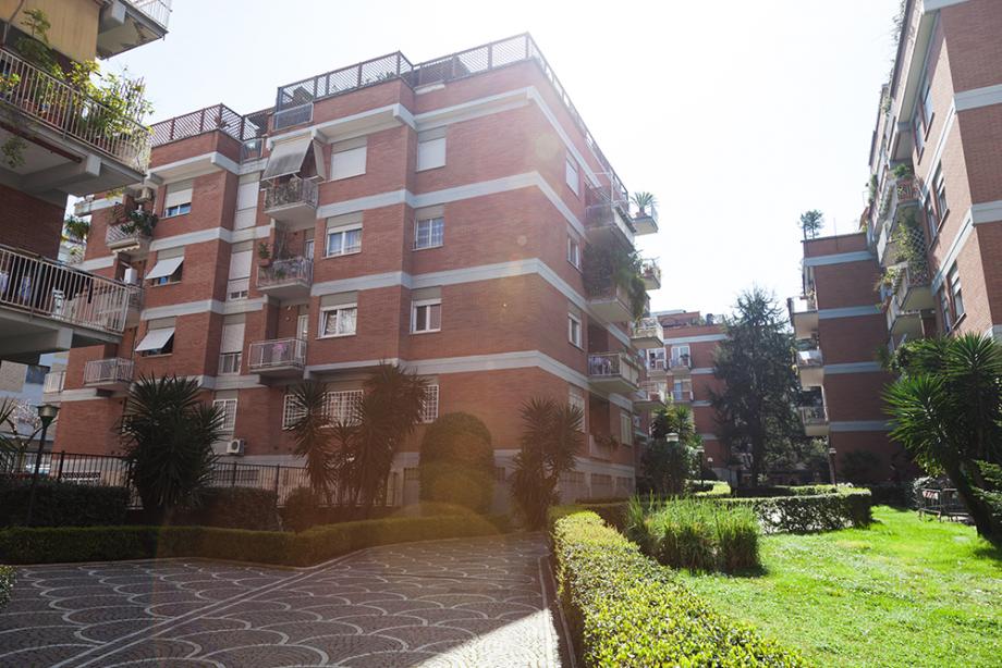
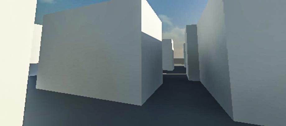
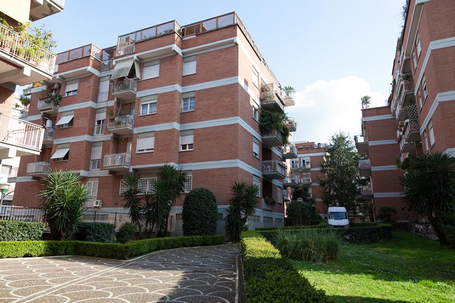
Adesso compariamo il modello virtuale con le immagini reali del sito. Notiamo dal confronto, l'accuratezza del software che ci permettere di conoscere in che maniera gli edifici del sito verranno investiti dall'ombra proiettata dai fabbricati contigui. (Fig.6.1 - 6.2)
Per il confronto abbiamo scelto tre orari differenti nello stesso giorno, ma la verifica può essere eseguita in qualsiasi orario di ciascun giorno dell'anno. Infatti estendiamo l'analisi a quattro giorni notevoli dell'anno, per evidenziare la variazione dell'angolo d'incidenza dei raggi solari.
- Equinozi di Primavera/Autunno: 20 marzo, 23 settembre (che hanno ombreggiamenti identici) (Fig.7.1)
- Solstizio di Estate: 21 giugno (Fig.7.2)
- Solstizio di Inverno: 22 dicembre (Fig.7.3)
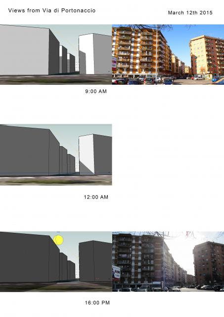
(fig.6.1)
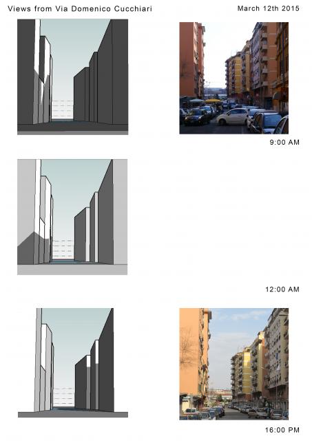
(fig.6.2)
Equinozi Primavera/Autunno
(fig.7.1)
Solstizio d'Estate
 (fig.7.2)
Solstizio d'Inverno
(fig.7.3)
Dom, 22/03/2015 - 18:15 Navarro_Stosic
Dom, 22/03/2015 - 16:48
Navarro_Stosic
Dom, 22/03/2015 - 16:48
Alleghiamo qua sotto il link della prima parte della prima esercitazione svolta l'anno scorso:
http://design.rootiers.it/tecniche2012/node/2911
Segue qui la seconda parte.
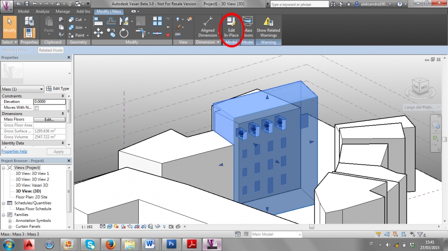
1) Aprire il progetto e selezionare un oggetto. Una volta selezionato l’edificio da modificare andare sul tab “Modify Mass” e cliccare su “Edit In-Place”.
First open the project and select the object. When you have selected the building to modify, go on the tab ''Modify Mass'' and click on ''Edit In-Place''.
Primero se abre el proyecto y se selecciona el objeto. Cuando se haya seleccionado el proyecto a modificar, ve al tab ‘’Modify Mass’’ y haz clic en ‘’Edit In-Place’’.
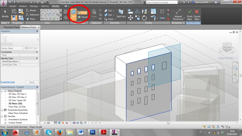
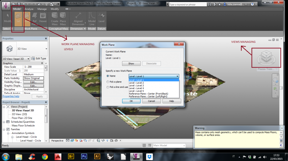
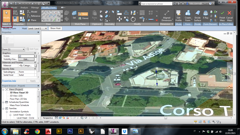
2) Per selezionare la superficie su cui si vuole lavorare cliccare sul comando “Set” nella sezione “Work Plane”. Selezionare la superficie e cliccare su “Show”.
For selecting the surface that you want to work on, you have to click on the command ''Set'' in the part of '' Work Plane''. Select the surface and click on ''Show''.
Para seleccionar las superficies en las que quieres trabajar, tienes que hacer click en el comando ‘’Set’’ en la parte de ‘’Work Plane’’. Selecciona la superficie y haz click en ‘’Show’’.
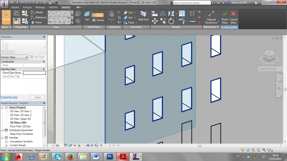
3) Per iniziare a creare le bucature che rappresentano le finestre, cliccare su “Rectangle”
For starting to create the hollow that represent the windows , click on '' Rectangle''.
Para empezar a crear el hoyo que representa las ventanas, haz click en ‘’Rectangle’’.
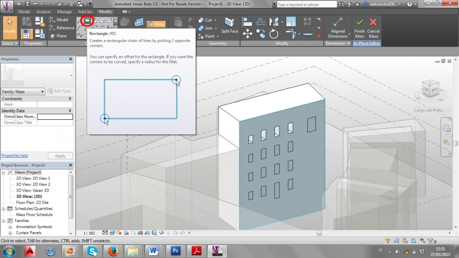
4) Creare un rettangolo con le misure corrette se possibile, altrimenti approssimarle. Per modificare le misure basta cliccare sui lati del rettangolo e scrivere quelle corrette.
If it's possible create a rectangle with the corrected or approximate measure. For modifying the measures it's enough to click a side of the rectangle and write the correct ones.
Si es posible se debe crear un rectángulo con las medidas correctas o aproximadas. Para modificar las medidas es suficiente hacer clic a un lado de el rectángulo y escribir las correctas.
5) Per modificare la distanza del rettangolo dai bordi dell’edificio, spostare il pallino delle quote fino al bordo e modificare la misura.
For modifying the rectangle's distances go to the edge of the building, move the dot of the dimensions up to the edge and modify the measures.
Para modificar las distancias del rectángulo se debe ir al borde y modificar las medidas.

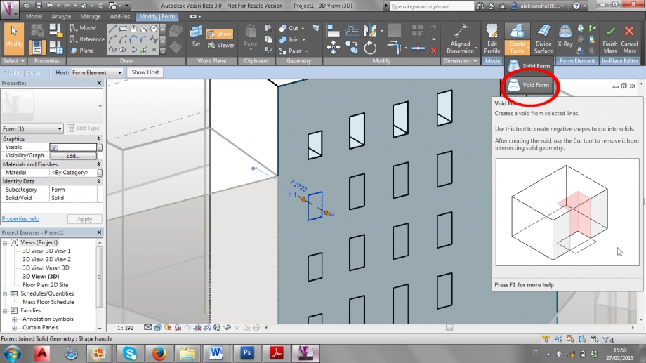
6) Per creare le bucature, cliccare all’interno del rettangolo e andare sul comando “Create Form”. Si aprirà un menù a tendina: cliccare su “Void Form”.
For creating the hollow, click inside the rectangle and go to the command ''Create form''. A drop down menu will open: click on ''Void Form''.
Para la creación del hoyo haz clic dentro de el rectángulo y ve al comando ‘’Create Form’’. Una ventana desplegable del menú se abrirá: hacer clic en''Void Form''.
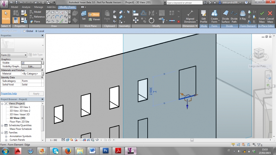
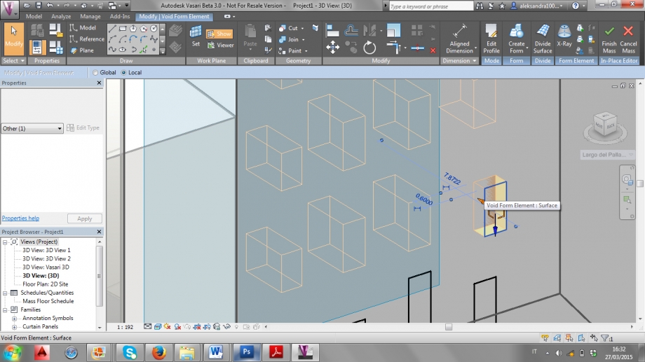
7) Attivato il comando “Void Form”, tirare la freccia arancione verso l’interno per creare la bucatura, poi cliccare sulla misura per modificarne la profondità.
When the command ''Void Form'' its activated, pull the orange arrow inside for create the hollow and then click on their measure for modifying the profundity.
Cuando el comando ''Void Form'' sea activado, hala la flecha anaranjada dentro para crear el hoyo y después haz clic en sus medidas para modificar la profundidad.
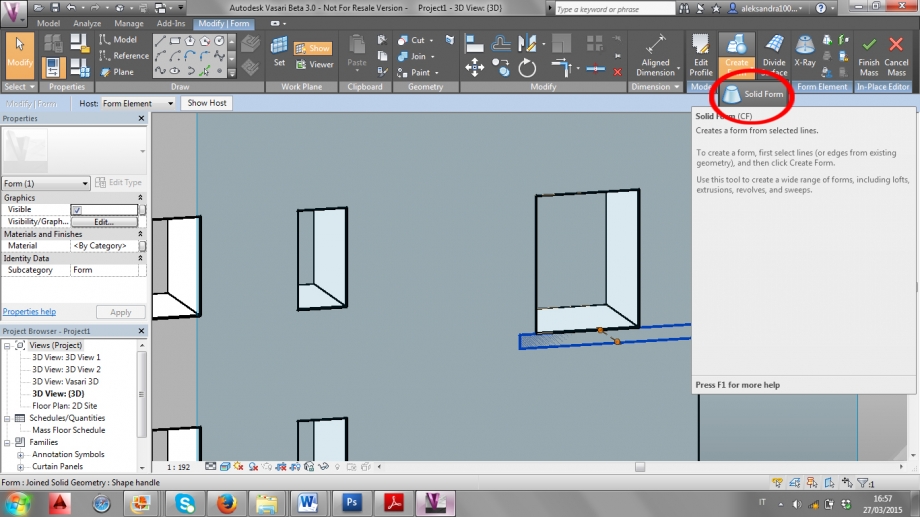
8) Per creare una pensilina, dopo aver disegnato un rettangolo e modificato le misure, cliccare al centro del rettangolo. Andare sul comando “Create Form” e nel menù a tendina cliccare su “Solid Form”.
For the creation of a shelf, after drawing a rectangle and modifying the measure, click inside of the rectangle and go to the command ''Create Form'' and in the drop down menu click on ''Solid Form''.
Para la creación de una superficie, después de diseñar el rectángulo y modificar las medidas haz clic dentro del rectángulo y ve al comando ''Create Form'' y en la ventana desplegable del menú haz clic en ‘’Solid Form’’.
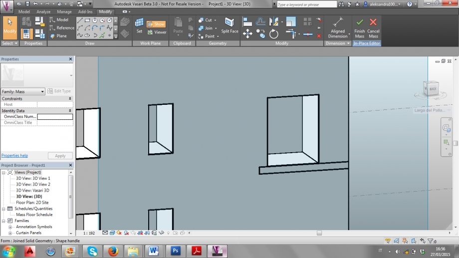
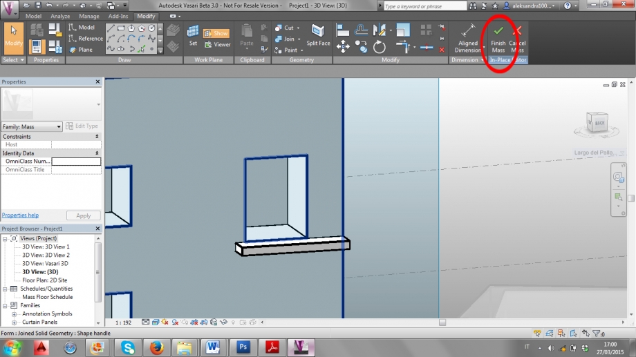
9) Tirare la freccia arancione verso l’esterno e modificare le misure. Terminate tutte le bucature e pensiline cliccare sul comando “Finish Mass”.
Pull the orange arrow outside and modify the measure. when you finish all the hollows and shelves click on the command ''Finish mass''
Poner la flecha anaranjada afuera y modificar las medidas. Cuando tu hayas terminado todos los hoyos y superficies haz clic en el comando ''Finish mass''.
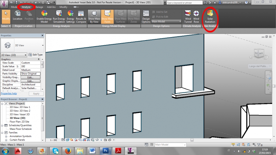
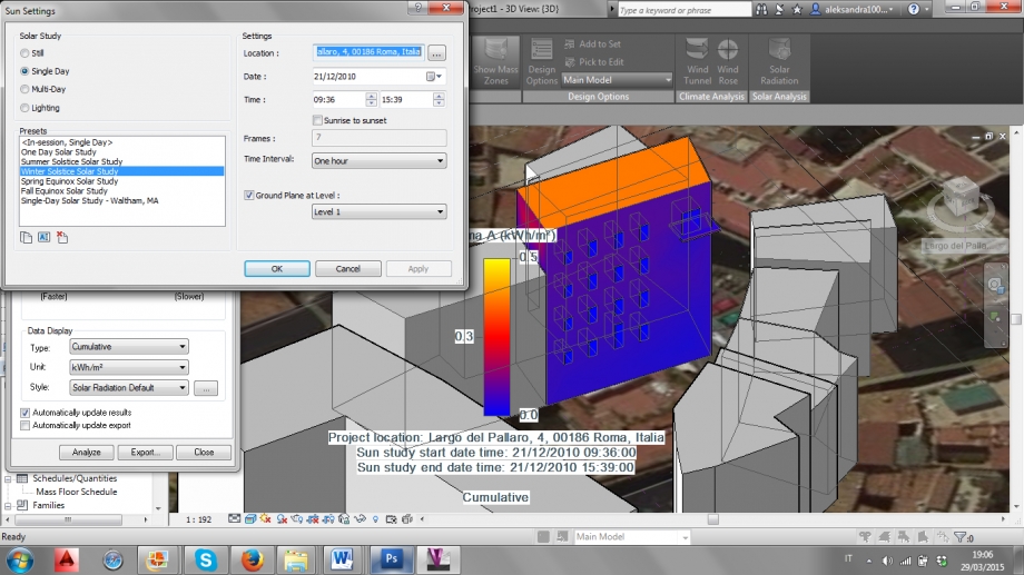
10) Andare sul tab “Analyze” e nella sezione “Solar Analisys” cliccare sul comando “Solar Radiation”.
Go on the tab ''Analyze'' and on the part ''Solar Analisys'' click on command ''Solar Radiation''.
Ve al tab ''Analyze'' en la parte de ''Solar Analisys'' haz clic en el comando ''Solar Radiation''.
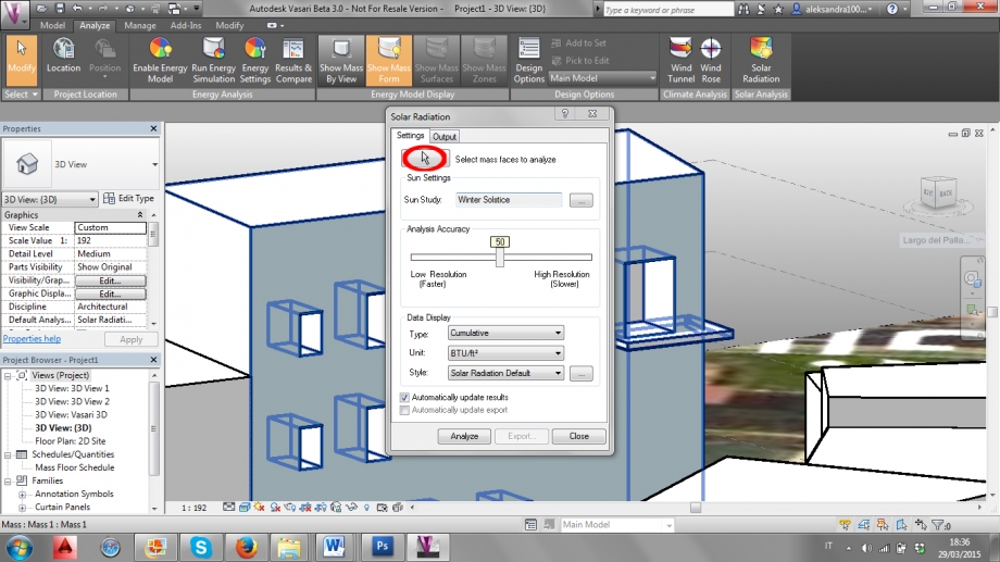
11) Una volta aperto il comando, cliccare sul tasto con la freccia per selezionare le parti dell’edificio su cui si vuole effettuare l’analisi solare.
Once the command is open, click on the button with the arrow to select the parts of the buildings in which you want to make the Solar analysis.
Una vez que el comando sea abierto, haz clic con la flecha en el botón para seleccionar las partes del edificio en las cuales tu desees hacer el análisis Solar.
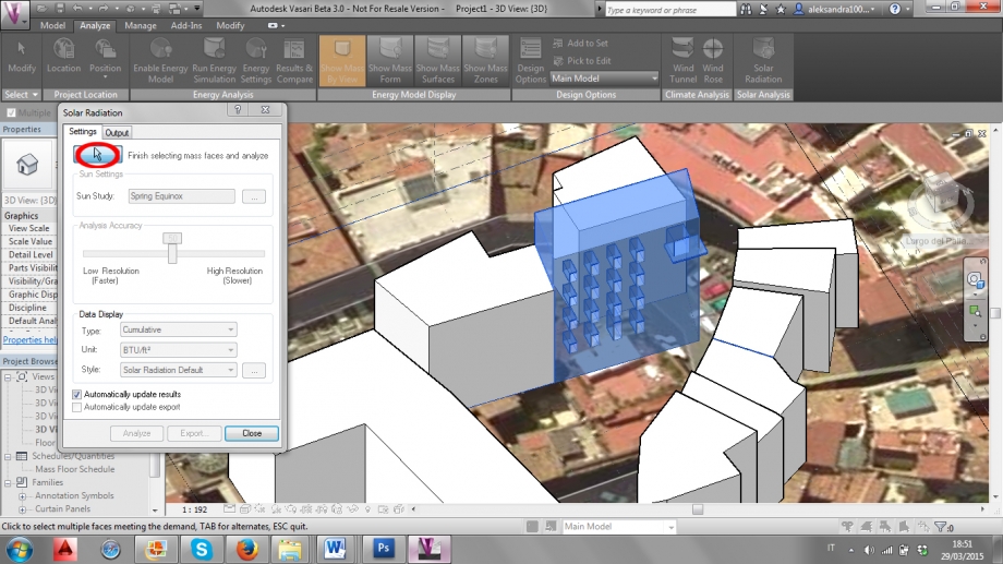
12) Dopo aver selezionato le parti dell’edificio, cliccare di nuovo sul tasto con la freccia per chiudere l’operazione di selezione.
After selecting the parts of the building, click again on the button with the arrow for closing the selecting operation.
Después de seleccionar las partes de el edificio haz clic con la flecha en el botón para cerrar la operación.
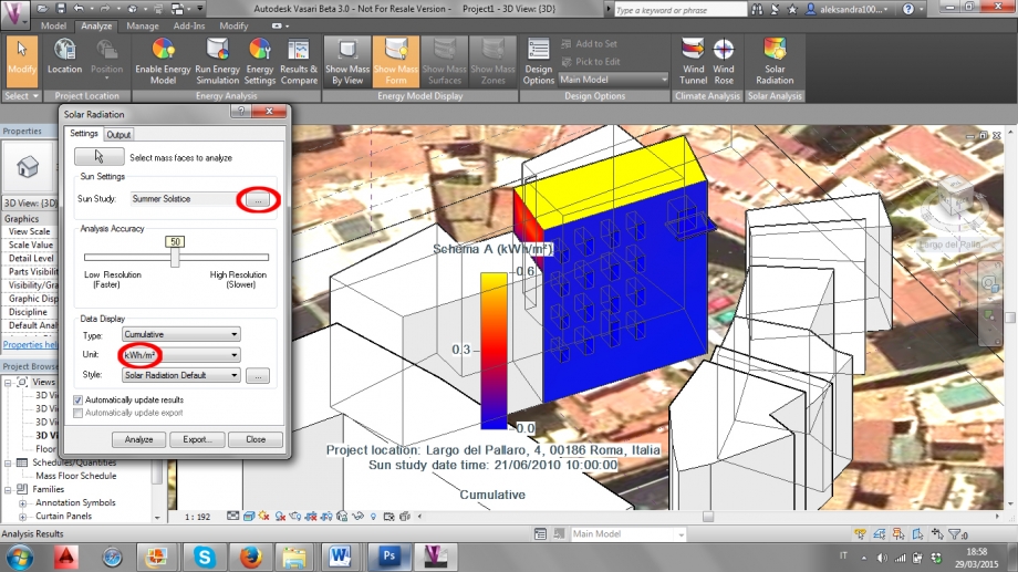
13) Nella sezione “Data Display”, cambiare le unità di misura da BTU/ft² a kWh/m². Cambiare le impostazioni dell’irraggiamento solare nella sezione “Sun Settngs”, “Sun Study”.
In the section “Data Display” change the units from BTU/ft² to kWh/m². Change the settings of the solar radiation in the section “Sun Settings”, then “Sun Study”.
En la seccion ‘’Data Display” cambiar la unidad de medda de BTU/ft² a kWh/m². Cambiar los ajustes de La Radiacion Solar en la seccion “Sun Settings”, despues “Sun Study”.
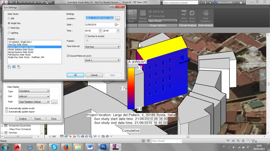
14) Per analizzare l’irraggiamento solare nella giornata del solstizio d’estate, impostare lo studio su “Single Day”, selezionare “Summer Solstice Solar Study” e modificare l’ora dalla quale e alla quale si vuole compiere l’analisi. Cliccare su “Ok” per far partire l’analisi. Per effetuare l’analisi nella giornata del solstizio d’inverno, bisogna invece selezionare “Winter Solstice Solar Study”.
For analyzing the solar radiation in the summer solstuce day, set the study on “Single Day”, select “Summer Solstice Solar Study” and modify the hours from when to when the analysis is needed. Click on “Ok” to start the analysis. For making an analysis for the winter solstice day, select “Winter Solstice Solar Study” instead.
Para analizar la radiaccion solar en el dia de solstizio de verano, selecciona “Summer Solstice Solar Study” y modifica las horas de cuando a cuando el analisis sea necesitado. Clic en “Ok” para empezar el analisis. Para hacer un analisis de el dia de solstizio en invierno, es necesario seleccionar “winter Solstice Solar Study”.
Considerazioni:
Abbiamo effetuato sia analisi solare di tipo “still” incentrata su dei momenti precisi della giornata, che un’analisi che considerasse l’intera giornata, ma la facciata dell’edificio che abbiamo preso in considerazione non riceve un irraggiamento solare diretto, è sempre in ombra. Questo fa sì che lo studio di eventuali pensiline non sia interessante, dal momento che l’intera facciata dell’edificio non si trova in una situazione ottimale.
Inoltre c’è stata qualche difficoltà nel selezionare gli elementi dell’edificio per l’analisi, in quanto durante questa azione gli elementi continuavano a deselezionarsi tutti improvvisamente. Dopo quattro tentativi abbiamo sviato il problema selezionando l’intero edificio con il rettangolo della selezione, deselezionando poi quelli elementi che non ci interessavano.
Considerations:
We made both a still solar analysis, incentrated at specific times of the day, and a single day analysis, but the facade of the building we are considering doesn’t get any direct solar radiation, it’s always in shadow. This makes pointless any kind of study of the shelves that are on the facade, since the whole facade is not in a great situation.
Moreover we had some difficulties while selecting the elements of the building for the analysis, as during this action the elements continued deselecting themselves. After four attempts we avoided the problem selecting the whole building with the rectangular selection, deselecting then the elements that we didn’t need.
Consideración:
Hemos efectuado ambos análisis solares de tipo ‘’Still’’ centrados en horas especificas del día,y de un solo día de análisis, pero la fachada del edificio que habíamos analizado no recibe una radiación directa, esta siempre en penumbra. Esto ocasiona que el estudio de la fachada y las superficies no sea interesante; desde el momento en que la fachada del edificio no se encuentra en situaciones optimas.
Además se tenido dificultadescuando seleccionamos los elementos del edificio para el análisis, tanto como duro el proceso los elementos se deseleccionaban ellos mismos. Después de cuatro intentos pudimos solucionado el problema seleccionando todo el edificio con el rectángulo de selección, deseleccionando después los elementos que no nos interesaban.
 Monaco_Zianna
Dom, 22/03/2015 - 16:08
Monaco_Zianna
Dom, 22/03/2015 - 16:08
FIRST DELIVERY TASK
We had to choose one building in order to develp a solar analysis. The aim is to produce a model which reflects the shadows pictured at two different times of a choosen day. The software selected to complete this assignment is Autodesk Vasari.
ABOUT THE SITE
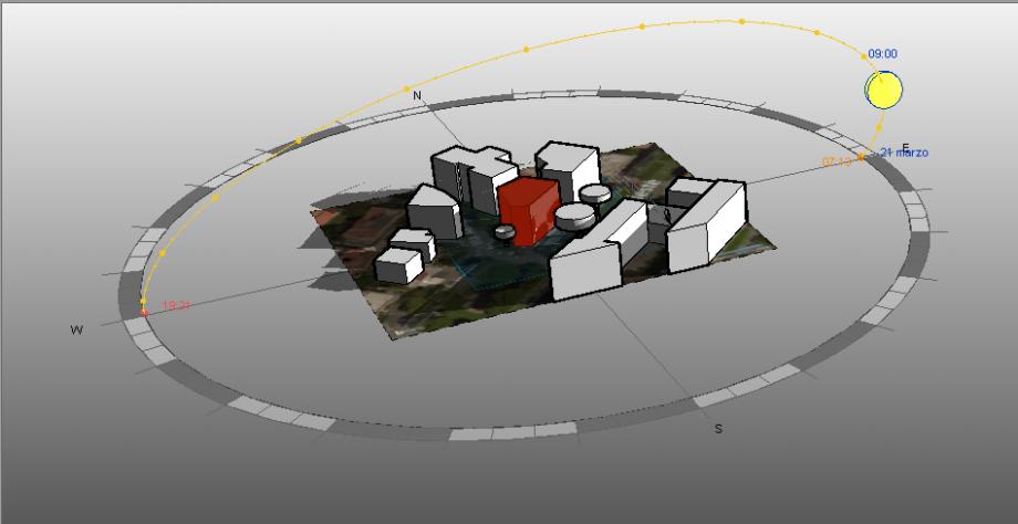
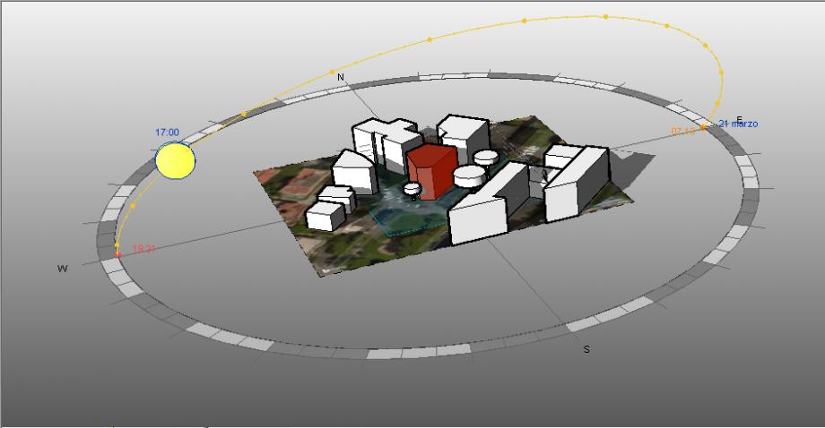
The building is located at the corner between Trasimeno Square and Corso Trieste, Trieste district, Rome, Italy. It presents 6 floors in couple with the nearest buildings. Due to the notable dimentions of the street and the square, the other buildings do not considerably contribute to the shadows on ours. For this reason, we decided to model trees too; at the selected times, indeed, the only visible shadows on the building are the ones generated by the near trees.
We took a picture of the building on 21st March 2015 at 9.00 am and 5.00 pm.
SOLAR ANALYSIS
Location:
Picture and Model
9.00 am
5.00 pm
CONSIDERATIONS
The entrance of the building is oriented towards S/ S-W . Thus, one of the main facade of the building is oriented at East and the other at West. The first one, due to the dimension of Corso Trieste, does not present any shadows caused by other buildings, at any time. This is why we had to model trees too, because they are important elements for shading the facade. The other facade, is always in the shade, due to its West exposition the low rise rays of sun do not reach the facade, they are stopped by the building that is on the other side of the street. From the internal point of view, the house presents its day zone facing East and the night zone facing North. This has been undoubtedly a choice made considering the orientation of the building. Our building produces shades only on the building behind, and leave, instead, the square in light.
HOW WE HAVE DONE THIS - TUTORIAL
1) Localization
a. Open file
b. Set location
Since Vasari is a software beta that integrates 3D conceptual modeling with energy analysis, one needs to georeference all projects.
c. Set meteo station
Is not always the nearest meteo station the one to chose. The perfect meteo station should be near, reliable, situated in a place with similar altitude and meteorological conditions. For this reason, we have choosen Ciampino Meteo Station instead of the nearer Monte Sacro one.
d. Import site image
2) Modeling
a. Set project units
Vasari works in scale 1:1. Modeling buildings, it is advisable to use meters units insted of centimeters or millimeters ( it is the same for feet and inches).
b. Views and work plane management
c. Create mass
d. Complete model
3) Solar Analysis
a. Sun setting
In order to set the solar analysis, one has to set chosen date and time.
b. Display Shadows